Appendix A
Explanatory Material for Division B
Explanatory Material for Division BCopy linkAdd bookmark
A-1.1.2.1.(2) Winter Design Temperatures. Copy linkAdd bookmark
The 2.5 percent values referenced in Sentence 1.1.2.1.(2) are the least restrictive temperatures that can be used. If a designer chooses to use the 1 percent values shown in MMAH Supplementary Standard SB-1, they would be in excess of the Code minimums and would be considered acceptable.
A-1.3.2.1. Abbreviations of Proper Names. Copy linkAdd bookmark
The following table provides contact information for organizations referenced in this Code:
| Name | Address | Contact |
|---|---|---|
| ACGIH | American Conference of Governmental Industrial Hygienists 1330 Kemper Meadow Drive Cincinnati, Ohio 45240 USA | ph: 513-742-2020 fax: 513-742-3355 web site: www.acgih.org |
| AISI | American Iron and Steel Institute 25 Massachusetts Ave., NW Suite 800 Washington, DC 20001 USA | ph: 202-452-7100 fax: 202-452-1039 web site: www.steel.org |
| ANSI | American National Standards Institute 25 West 43rd Street, 4th Floor New York, New York 10036 USA | ph: 212-642-4900 fax: 212-398-0023 web site: www.ansi.org |
| APA | The Engineered Wood Association 7011 S. 19th Street Tacoma, WA 98466-5333 USA | ph: (253) 620-7400 fax: (253) 565-7265 web site: www.apawood.org |
| APHA | American Public Health Association 800 I Street, NW Washington, DC 20001 USA | ph: 202-777-2742 fax: 202-777-2534 web site: www.apha.org |
| ASCE | American Society of Civil Engineers 1801 Alexander Bell Drive Reston, VA 20191 USA | ph: 800-584-2723 web site: www.asce.org |
| ASHRAE | American Society of Heating, Refrigerating and Air-Conditioning Engineers 1791 Tullie Circle, N.E. Atlanta, Georgia 30329 USA | ph: 404-636-8400 800-527-4723 fax: 404-321-5478 web site: www.ashrae.org |
| ASME | The American Society of Mechanical Engineers Three Park Avenue New York, New York 10016-5990 USA | ph: 800-843-2763 fax: 973-882-1717 web site: www.asme.org |
| ASPE | American Society of Plumbing Engineers 6400 Shafer Court, Suite 350 Rosemont, Illinois 60018 USA | ph: 847-296-0002 fax: 847-296-2963 web site: www.aspe.org |
| ASSE | American Society of Sanitary Engineering 901 Canterbury Suite A Westlake, Ohio 44145 USA | ph: 440-835-3040 fax: 440-835-3488 web site: www.asse-plumbing.org |
| ASTM | American Society for Testing and Materials 100 Barr Harbor Drive PO Box C700 West Conshohocken, Pennsylvania 19428-2959 USA | ph: 610-832-9585 fax: 610-832-9555 web site: www.astm.org |
| AWS | American Welding Society 8669 NW 36th Street, Suite 130 Doral, Florida 33166 USA | ph: 800-443-9353 fax: 305 - 443-5647 web site: www.aws.org |
| AWWA | American Water Works Association 6666 W. Quincy Ave. Denver, Colorado 80235 USA | ph: 303-794-7711; 800-926-7337 fax: 303-347-0804 web site: www.awwa.org |
| BCMOHS | British Columbia Ministry of Health Population Health and Wellness, Health Protection 1515 Blanshard Street, 4th Floor Victoria, British Columbia V8W 3C8 | ph: (250) 952-1469 fax: (250) 952-1713 web site: http://www.health.gov.bc.ca |
| BNQ | Bureau de Normalisation du Québec 333, rue Franquet Québec, Québec G1P 4C7 | ph: 418-652-2238 800-386-5114 fax: 418-652-2292 web site: www.bnq.qc.ca |
| CCBFC | Canadian Commission on Building and Fire Codes National Research Council Canada Building M-23A 1200 Montreal Road Ottawa, Ontario K1A 0R6 | ph: 613-993-9960 fax: 613-952-4040 web site: www.nationalcodes.ca |
| CGSB | Canadian General Standards Board 11 Laurier Street Gatineau, Quebec K1A 1G6 | ph: 819-956-0425 800-665-2472 fax: 819-956-5740 web site: www.pwgsc.gc.ca/cgsb |
| CSA | Canadian Standards Association 5060 Spectrum Way, Suite 100 Mississauga, Ontario L4W 5N6 | ph: 416-747-4044 800-463-6727 fax: 416-747-2510 web site: www.csa.ca |
| CWC | Canadian Wood Council 99 Bank Street, Suite 400 Ottawa, Ontario K1P 6B9 | ph: 613-747-5544 800-463-5091 fax: 613-747-6264 web site: www.cwc.ca |
| DBR | Institute for Research in Construction National Research Council Canada Building M-23A 1200 Montreal Road Ottawa, Ontario K1A 0R6 The Division of Building Research (DBR) is now known as the Institute for Research in Construction. | ph: 613-993-9960 fax: 613-952-4040 web site: www.nationalcodes.ca |
| EPA | Environmental Protection Agency Ariel Rios Building 1200 Pennsylvania Avenue, N.W. Washington, DC 20460 USA | ph: (202) 272-0167 web site: www.epa.gov |
| FINA (now World Aquatics) | World Aquatics Chemin de Bellevue 24a/24b CH-1005 Lausanne, Switzerland | ph: (+41-21) 310-47-10 web site: www.worldaquatics.com |
| GRHC | Green Roofs for Healthy Cities 406 King Street East Toronto, Ontario M5A 1L4 | ph. 416-971-4494 web site: www.greenroofs.org |
| HC | Health Canada Address Locator 0900C2 Ottawa, Ontario K1A 0K9 | ph: 866-225-0709 fax: 613-941-5366 web site: www.hc-sc.gc.ca |
| HI | Hydronics Institute Division of GAMA 35 Russo Place P.O. Box 218 Berkeley Heights, New Jersey 07922 USA The Hydronics Institute was formally merged into GAMA in 2004. | ph: 866-408-3831 908-464-8200 fax: 908-464-7818 web site: www.gamanet.org |
| HPVA | Hardwood Plywood & Veneer Association (Now Decorative Hardwoods Association) 42777 Trade West Dr Sterling, VA 20166 USA | ph: 703-435-2900 fax: 703-435-2573 web site: decorativehardwoods.org |
| HRAI | Heating, Refrigerating and Air-Conditioning Institute of Canada 2800 Skymark Avenue Building 1, Suite 201 Mississauga, Ontario L4W 5A6 | ph: 905-602-4700 800-267-2231 fax: 905-602-1197 web site: www.hrai.ca |
| HVI | Home Ventilating Institute 1000 N. Rand Rd. Suite 214 Wauconda, Illinois 60084 USA | ph: 847-526-2010 fax: 847-526-3993 web site: www.hvi.org |
| IAPMO | International Association of Plumbing and Mechanical Officials 4755 E. Philadelphia St. Ontario, California 91761 USA | ph: 909-472-4100 fax: 909-472-4150 web site: iampo.org |
| IESNA | Illuminating Engineering Society of North America 120 Wall Street, Floor 17 New York, New York 10005-4001 USA | ph: 212-248-5000 fax: 212-248-5017 web site: www.iesna.org |
| ISO | International Organization for Standardization ISO Central Secretariat 1, ch. de la Voie-Creuse CP 56 CH-1211 Geneva 20, Switzerland | ph: 41-22-749-01-11 fax: 41-22-733-34-30 web site: www.iso.org |
| HUD | U.S. Department of Housing and Urban Development HUD established HUD USER as the primary source of US government technical housing publications. HUD USER P.O. Box 23268 Washington, DC 20026-3268 USA | ph: 202-708-3178 800-245-2691 fax: 202-708-9981 web site: www.huduser.org |
| MOE (now MECP) | Ontario Ministry of the Environment (Ontario Ministry of the Environment, Conservation and Parks) 135 St Clair Avenue West Toronto, Ontario M4V 1P5 | ph: 416-325-4000 fax: 416-314-6713 web site: www.ontario.ca/ministry-environment-conservation-parks |
| NFPA | National Fire Protection Association 1 Batterymarch Park Quincy, Massachusetts 02169-7471 USA | 617-770-3000 fax: 617-770-0700 web site: www.nfpa.org |
| NFRC | National Fenestration Rating Council 6305 Ivy Lane, Suite 140 Greenbelt, MD 20770, USA | ph: 301-589-1776 fax: 301-589-3884 web site: www.nfrc.org |
| NLGA | National Lumber Grades Authority #302 - 960 Quayside Drive, New Westminster, British Columbia V3M 6G2 | ph: 604-524-2393 fax: 604-524-2893 web site: www.nlga.org |
| NRCan | Natural Resources Canada Office of Energy Efficiency 580 Booth St., 18th Floor Ottawa, Ontario K1A 0E4 | ph: 613-995-2943 800-387-2000 web site: www.nrcan-rncan.gc.ca |
| NSF | NSF International P.O. Box 130140 789 N. Dixboro Road Ann Arbor, Michigan 48113-0140 USA | ph: 734-769-8010 fax: 734-769-0109 web site: www.nsf.org |
| SEI | See ASCE | |
| SMACNA | Sheet Metal and Air Conditioning Contractors National Association Inc. 4201 Lafayette Center Drive Chantilly, Virginia 20151-1219 USA | ph: 703-803-2980 fax: 703-803-3732 web site: www.smacna.org |
| SPRI | Single Ply Roofing Industry 465 Waverley Oaks Road Suite 421 Waltham, MA 02452 | ph: 781-647-7026 fax: 781-647-7222 web site: www.spri.org |
| TC | Transport Canada 330 Sparks Street Ottawa, Ontario K1A 0N5 | ph: 613-990-2309 866-995-9737 fax: 613-954-4731 web site: www.tc.gc.ca |
| TPIC | Truss Plate Institute of Canada c/o Jager Metal Products, #220 6223 2nd Street East, Calgary, Alberta T2H 1J5 The TPIC, “Truss Design Procedures and Specifications for Light Metal Plate Connected Wood Trusses” is available on-line at: the TPIC web site at: www.tpic.ca. | web site: www.tpic.ca |
| UL | Underwriters Laboratories Inc. 333 Pfingsten Road Northbrook, Illinois 60062-2096 USA | ph: 847-272-8800 web site: www.ul.com |
| ULC | Underwriters' Laboratories of Canada 7 Underwriters Road Toronto, Ontario M1R 3A9 | ph: 866-937-3852 fax: 416-757-8727 web site: www.ulc.ca |
| USDA | United States Department of Agriculture 1400 Independence Ave., S.W. Washington, DC 20250 USA | web site: www.usda.gov |
| WEF | Water Environment Federation 601 Wythe Street Alexandria, Virginia 22314-1994 USA | ph: 800-666-0206 fax: 703-684-2492 web site: www.wef.org |
| WT | Waterfront Toronto 20 Bay Street, Suite 1310 Toronto, Ontario M5J 2N8 | ph: 416-214-1344 fax: 416-244-4591 web site: info@waterfrontoronto.ca |
A-2 Application of Part 2.Copy linkAdd bookmark
Part 2 of the Building Code contains specific requirements pertaining to farm buildings because they have distinct characteristics compared to other types of buildings: they have low occupant loads, are typically located in rural settings, and house unique activities and contents. Part 2 does not apply to large farm buildings that do not qualify as having “low human occupancy,” i.e., an occupant load of not more than 1 person per 40 m2 of floor area.
A-2.1.1.1.(1) Safety of Persons. Copy linkAdd bookmark
The intent of Part 2 is to set forth measures to ensure the safety of persons in farm buildings.
A-2.1.4.1.(1) Major Occupancy Classifications for Farm Buildings. Copy linkAdd bookmark
The following are examples of the agricultural major occupancy classifications described in Table 2.1.4.1.:
Group G, Division 1 Farm buildings housing livestock with a below-floor storage area for liquid manure Feed mills Grain elevators Rooms for the bulk storage of dangerous goods classified as flammable gases or compressed gases Rooms for the bulk storage of flammable liquids Rooms for the bulk storage of reactive materials
Group G, Division 2 Animal exercise facilities Animal housing facilities, including, but not limited to, facilities for livestock, facilities for alternative livestock and game animals, facilities for fur-bearing animals, and facilities for cultured fish and shellfish Animal training facilities Facilities for the packaging and processing of agricultural products Facilities for the production of plants and fungi, excluding greenhouses Farm workshops Feed preparation centres Feed storage facilities Fruit and vegetable storage facilities Grain, forage and feed structures Milking facilities Storage facilities for farming equipment, implements and machinery Viniculture facilities
Group G, Division 3 Greenhouses
Group G, Division 4 Biomass facilities By-product facilities Digesters Grain bins Horizontal silos Storage bins Vertical silos
A-2.2.1.1.(2) Non-Agricultural Major Occupancies. Copy linkAdd bookmark
It is intended that portions of farm buildings that contain permitted major occupancies other than agricultural major occupancies be subject to the requirements of Part 3. Unless specifically referenced in Part 2, the requirements of Part 3 are not intended to be applied to portions of farm buildings meeting the criteria for the application of Part 2. (See Articles 2.1.2.1. and 2.1.2.2.)
A-2.2.1.5. Environmental Conditions. Copy linkAdd bookmark
The materials used in the construction of fire separations and closures in farm buildings should be selected to minimize deterioration caused by exposure to corrosive or humid environmental conditions.
A-2.2.1.8.(1) Concealed Spaces Used as Supply Air Plenums. Copy linkAdd bookmark
Sentence 2.2.1.8.(1) is not intended to prohibit a concealed attic or roof space from being used as a supply air plenum for the distribution of air through a porous ceiling or ceiling inlets to the space below.
A-2.2.1.15.(2) Damage to Electrical Wiring. Copy linkAdd bookmark
The protection required by Sentence 2.2.1.15.(2) is intended to prevent rodents from damaging electrical wiring that is installed in a concealed space, such as a space within an assembly, an attic space, or a service space.
A-2.2.7.1.(1) Exiting from Floor Areas. Copy linkAdd bookmark
The intent of Sentence 2.2.7.1.(1) is that each floor level be served by its own exits. This approach to providing exits is consistent with that in Part 3.
A-2.2.7.2. Overhead Doors and Sliding Doors. Copy linkAdd bookmark
Overhead doors and sliding doors are not permitted to be used as exits from farm buildings with human occupants because such doors could delay their egress.
A-2.2.8.2.(3) Ventilation of Below-Floor Storage Areas for Liquid Manure. Copy linkAdd bookmark
Where a farm building housing livestock with a below-floor storage area for liquid manure is provided with a ventilation system in accordance with Article 2.2.8.3., the requirements of Sentences 2.2.8.2.(1) and (2) are considered to be satisfied with respect to the fire and explosion hazard posed by manure gases. Should other hazardous substances or conditions be present in the farm building, the requirements of Sentences 2.2.8.2.(1) and (2) must be applied with respect to those substances or conditions.
A-2.2.8.3. Below-Floor Storage Areas for Liquid Manure. Copy linkAdd bookmark
The following are examples of manure-handling equipment and systems that are not considered to be below-floor storage areas for liquid manure:
- gutters, pumps and pump chambers designed to be emptied or flushed every few days
- shallow gutters
- gutters scraped with an alley scraper or stable cleaner
- gutters equipped with a belt manure removal system
- normally empty transfer gutters and pipes
A-2.2.8.4.(1) Welding and Cutting. Copy linkAdd bookmark
The room referred to in Sentence 2.2.8.4.(1) is a space where significant and regular welding and cutting operations are routinely performed, such as a welding shop supporting the farm operation. Sentence 2.2.8.4.(1) is not intended to apply to occasional welding and cutting operations, such as those carried out during repairs of farm machinery.
Refer to Section 5.2. of Division B of the NFC for requirements relating to hot works, including cutting, welding, soldering, brazing, grinding and adhesive bonding.
A-2.2.8.6. Liquids Capable of Releasing Hazardous Gases or Vapours. Copy linkAdd bookmark
Examples of liquids that are capable of releasing hazardous gases or vapours include liquid manure, wash water from a milking facility, and waste water in a septic system.
A-2.3.1.1.(1) Design of Bins and Silos. Copy linkAdd bookmark
Information on the design of bins and silos can be found in the Commentary entitled Farm Buildings in the “Structural Commentaries (User's Guide – NBC 2020: Part 4 of Division B”.
A-2.3.2.3.(1) Bulk Densities of Agricultural Products. Copy linkAdd bookmark
The bulk densities, ρ, of agricultural products listed in Table A-2.3.2.3.(1) can be used to determine the specific weight, γ, of the products as follows:
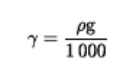
where γ = specific weight, in N/m3, ρ = bulk density, in kg/m3, and g = gravitational acceleration, in m/s2.
| Agricultural Product | Bulk Density, kg/m3 |
|---|---|
| Grains and Seeds(1) | |
| Alfalfa | 750 |
| Alsike | 740 |
| Barley | 620 |
| Beans | |
| castor | 590 |
| lima | 720 |
| navy | 770 |
| snap | 380 |
| Bentgrass | 450 |
| Birdsfoot trefoil | 740 |
| Bluegrass | |
| Canada | 270 |
| Kentucky | 280 |
| rough | 270 |
| Bromegrass | 170 |
| Buckwheat | 640 |
| Canola | 640 |
| Argentine rape | 640 |
| turnip or Polish rape | 770 |
| Clover | |
| red | 750 |
| sweet | 780 |
| white | 760 |
| Corn | |
| ear-husked | 450 |
| shelled | 720 |
| Cottonseed | 410 |
| Cowpeas | 770 |
| Fescue | |
| chewings | 240 |
| meadow | 290 |
| red | 220 |
| tall | 280 |
| Flaxseed (linseed) | 700 |
| Grain sorghums | 720 |
| Lentils | 770 |
| Milkvetch | 820 |
| Millet | 640 |
| Mustard | 640 |
| Oats | 420 |
| Orchard grass | 200 |
| Grains and Seeds(1) | |
| Peanuts | |
| shelled | 640 |
| unshelled | 240 |
| Peas | 770 |
| Rapeseed (see Canola) | |
| Red top | 390 |
| Reed canary grass | 380 |
| Rice | |
| hulled | 770 |
| rough | 580 |
| Russian wild rye | 250 |
| Rye | 720 |
| Ryegrass | |
| annual | 360 |
| perennial | 300 |
| Safflower seed | 720 |
| Sainfoin | 360 |
| Soybeans | 770 |
| Sunflower seed | 310 – 410 |
| Timothy | 580 |
| Wheat | 770 |
| Concentrated Feeds | |
| Alfalfa | |
| meal | 250 – 350 |
| pellets | 650 – 700 |
| Barley | |
| ground, meal | 380 – 450 |
| malt | 500 |
| Beet pulp, dried | 180 – 250 |
| Bone meal | 800 – 960 |
| Bran, rice-rye-wheat | 260 – 320 |
| Brewer's grain | |
| spent, dry | 220 – 290 |
| spent, wet | 880 – 960 |
| Corn | |
| cobs, ground | 270 |
| cobs, whole | 190 – 240 |
| cracked | 640 – 800 |
| germ | 340 |
| grits | 640 – 720 |
| meal | 510 – 640 |
| Concentrated Feeds | |
| Corn oil, cake | 400 |
| Crumbled ration | 550 |
| Fish meal | 560 – 640 |
| Flaxseed oil (linseed oil) | |
| cake | 770 – 800 |
| meal | 400 – 720 |
| Malt | |
| dry, ground | 320 – 480 |
| meal | 580 – 640 |
| Meat meal | 600 |
| Oats | |
| crimped | 300 – 420 |
| crushed | 350 |
| rolled | 300 – 420 |
| Pelleted ration | 600 |
| Salt | 1000 – 1100 |
| Soya bean meal | 550 – 650 |
| Wheat | |
| cracked | 640 – 720 |
| germ | 350 – 450 |
| Roughage Feeds and Bedding | |
| Hay (air-dried) | |
| baled | 160 |
| chopped | 160 |
| long | 80 |
| wafered | 325 |
| Straw | |
| chopped | 100 – 130 |
| field-baled | 130 |
| long | 60 |
| Wood shavings, baled | 320 |
| Fruits and Vegetables | |
| Apples, bulk | 600 |
| Apricots | 620 |
| Fruits and Vegetables | |
| Beans | |
| shelled | 800 |
| unshelled | 400 |
| Beets | 700 |
| Blackberries | 610 |
| Cabbage | 500 |
| Carrots | 550 |
| Cauliflower | 320 |
| Corn, cob | 450 |
| Cranberries | 480 |
| Cucumbers | 620 |
| Onions, dry | 650 |
| Parsnips | 500 |
| Peaches | 620 |
| Pears | 640 |
| Peas | 390 |
| Peppers | 320 |
| Plums | 720 |
| Potatoes | 670 |
| Pumpkins | 600 |
| Squash | 600 |
| Sweet potatoes | 700 |
| Tomatoes | 680 |
| Turnips | 600 |
| Miscellaneous | |
| Eggs in cases | 200 |
| Fertilizer | 950 – 1 000 |
| Tobacco | 550 |
| Wool | |
| compressed bales | 775 |
| uncompressed bales | 200 |
| Fresh manure (feces and urine mixed) | 1000 |
Notes to Table A-2.3.2.3.(1):
A-2.3.2.5.(3) Lateral Ice Pressure in Liquid Manure Storage Tanks. Copy linkAdd bookmark
The lateral ice pressure in liquid manure storage tanks in an Ontario region has been found to reach 50 kPa acting over an ice thickness of 0.5 m. The ice thickness, and therefore the lateral ice load, depends on the geographic location. To calculate the lateral ice load for a particular location, a lateral ice pressure of 50 kPa is applied over the ice thickness expected in that location, which can be estimated from the location's degree-days below 18°C listed in Table 2 of Supplementary Standard SB-1 as follows:
ice thickness (location) = 0.5 m × (degree-days below 18°C (location) / degree-days below 18°C (location))
A-2.3.2.5.(4)(a) Lateral Earth Pressure on Walls of Liquid Manure Storage Tanks. Copy linkAdd bookmark
The lateral earth pressure referred to in Clause 2.3.2.5.(4)(a) should be based on the equivalent fluid density of the earth surrounding the liquid manure storage tank. Equivalent fluid densities for different types of soil are listed in Table A-2.3.2.5.(4)(a).
| Type of Soil | Equivalent Fluid Density, kN/m3 |
|---|---|
| Clean sand and gravel, well-drained | 4.7 |
| Sand and gravel with fines, restricted permeability | 5.7 |
| Stiff residual silts and clays | 7.0 |
| Soft silts and clays, poorly drained | 16.0 |
2.3.2.5.(6) Design of Liquid Manure Storage Tanks to Minimize Leakage. Copy linkAdd bookmark
In designing walls and bases of liquid manure storage tanks to minimize leakage of liquid manure, all factors that may influence the formation of cracks should be taken into account, including thermal effects, concrete shrinkage, structural movement, and material choice and installation. The control of crack formation to minimize leakage is particularly important for reinforced concrete structures to prevent corrosion of the reinforcing steel.
A-2.3.3.1.(1) Reduced Snow Loads for Unobstructed Slippery Roofs. Copy linkAdd bookmark
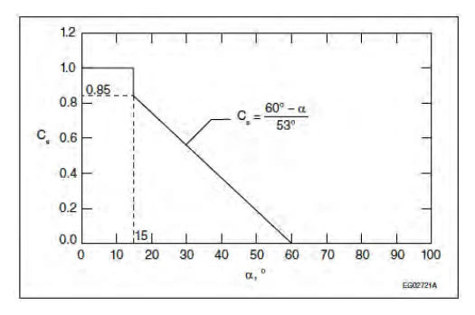
Research has shown that sloped roofs covered with pre-painted steel have reduced snow loads relative to roofs covered with asphalt shingles. Sentence 2.3.3.1.(1) allows a reduction of the slope factor, Cs, for unobstructed slippery roofs of farm buildings where the roof slope, α, is greater than 15° but not greater than 60°. Figure A-2.3.3.1.(1) shows the Cs versus α curve calculated in accordance with Sentence 2.3.3.1.(1).
Before using the reduced slope factor, the designer should carefully examine the proposed roof configuration to ensure that snow will freely slide off the roof. The reduced slope factor does not apply to sloped roofs terminating at grade, at a roof valley, or at another roof of lower slope because the snow may pile up or not slide freely at the transition in slope. The reduced slope factor also does not apply to roofs with obstructions, such as chimneys, silos or ice guards.
A-2.3.4. Seismic Design of Above-Ground Liquid Manure Storage Tanks. Copy linkAdd bookmark
Information on the seismic design of above-ground liquid manure storage tanks can be found in the Commentary entitled Farm Buildings in the “Structural Commentaries (User's Guide – NBC 2020: Part 4 of Division B)”.
A-2.3.4.1.(1)(b) SFRSs for Farm Buildings in Seismic Category SC2. Copy linkAdd bookmark
Information on SFRSs with RdRo ≥ 3.0 for farm buildings in Seismic Category SC2 can be found in the Commentary entitled
Farm Buildings in the “Structural Commentaries (User's Guide – NBC 2020: Part 4 of Division B)”.
A-2.4.2.1.(1) Required Ventilation. Copy linkAdd bookmark
Guidance on ventilation in farm animal housing and indoor plant agriculture facilities can be found in the chapter entitled Environmental Controls for Animals and Plants in the “ASHRAE Handbook – HVAC Applications”.
A-2.4.2.3. Controlled-Atmosphere Storage Areas. Copy linkAdd bookmark
Controlled-atmosphere storage areas are typically used to preserve fruits and vegetables and are not intended to contain hazardous gases.
A-2.4.2.4.(3) Gas Hazards in Enclosed Horizontal Silos. Copy linkAdd bookmark
In enclosed horizontal silos, gases produced by tractors during loading and unloading operations and by silage fermentation present a hazard. Providing openings at both roof or eave level and floor level in horizontal silos promotes airflow to remove these gases, most of which are heavier than air.
A-2.4.2.4.(3)(b) Openings at Floor Level in Enclosed Horizontal Silos. Copy linkAdd bookmark
The requirement of Clause 2.4.2.4.(3)(b) can be met by providing a single opening at floor level, which may also serve as a tractor access opening.
A-2.4.2.5. Below-Floor Storage of Liquid Manure. Copy linkAdd bookmark
The ventilation requirements of Article 2.4.2.5. are intended to address the specific hazards due to manure gases in farm buildings housing livestock with below-floor storage of liquid manure. Where these requirements are met, it is not necessary to apply the provisions of Articles 6.3.1.5. and 6.9.1.2. with respect to manure gases. However, where the farm building contains other hazardous substances (air contaminants or hazardous gases, dusts or liquids), the provisions of Articles 6.3.1.5. and 6.9.1.2. must be applied with respect to those substances.
A-2.4.2.5.(1) Minimum Ventilation Rate. Copy linkAdd bookmark
The minimum ventilation rate required by Sentence 2.4.2.5.(1) is intended to limit the concentrations of flammable gases and toxic gases produced by the decomposition of liquid manure. Higher ventilation rates may be necessary to promote farm animal health and production. Where requested by the authority having jurisdiction, compliance with Clauses 2.4.2.5.(1)(a) and (b) can be demonstrated through periodic in situ monitoring of gas concentrations or through calculation of gas concentrations using a reliable method (such as that described in the following publication: Massé, D.I., Croteau, F., Patni, N.K. and Masse, L. Methane Emissions from Dairy Cow and Swine Manure Slurries Stored at 10°C and 15°C. Canadian Biosystems Engineering, Vol. 45, pp. 6.1–6.6, 2003).
A-3 Application of Part 3.Copy linkAdd bookmark
In applying the requirements of this Part, it is intended that they be applied with discretion to buildings of unusual configuration that do not clearly conform to the specific requirements, or to buildings in which processes are carried out which make compliance with particular requirements in this Part impracticable.
The definition of “building” as it applies to this Code is general and encompasses most structures, including those which would not normally be considered as buildings in the layman’s sense. This occurs more often in industrial uses, particularly those involving manufacturing facilities and equipment that require specialized design that may make it impracticable to follow the specific requirements of this Part. Steel mills, aluminum plants, refining, power generation and liquid storage facilities are examples. A water tank or an oil refinery, for example, has no floor area, so it is obvious that requirements for exits from floor areas would not apply.
Requirements for structural fire protection in large steel mills and pulp and paper mills, particularly in certain portions, may not be practicable to achieve in terms of the construction normally used and the operations for which the space is to be used. In other portions of the same building, however, it may be quite reasonable to require that the provisions of this Part be applied (e.g., the office portions). Similarly, areas of industrial occupancy which may be occupied only periodically by service staff, such as equipment penthouses, normally would not need to have the same type of exit facility as floor areas occupied on a continuing basis. It is expected that judgement will be exercised in evaluating the application of a requirement in those cases when extenuating circumstances require special consideration, provided the occupants' safety is not endangered.
The provisions in this Part for fire protection features installed in buildings are intended to provide a minimum acceptable level of public safety. It is intended that all fire protection features of a building, whether required or not, will be designed in conformance with good fire protection engineering practice and will meet the appropriate installation requirements in relevant standards. Good design is necessary to ensure that the level of public safety established by the Code requirements will not be reduced by a voluntary installation.
Firefighting AssumptionsCopy linkAdd bookmark
The requirements of this Part are based on the assumption that firefighting capabilities are available in the event of a fire emergency. These firefighting capabilities may take the form of a paid or volunteer public fire department or, in some cases, a private fire brigade. If these firefighting capabilities are not available, additional fire safety measures may be required.
Firefighting capability can vary from municipality to municipality. Generally, larger municipalities have greater firefighting capability than smaller ones. Similarly, older, well-established municipalities may have better firefighting facilities than newly formed or rapidly growing ones. The level of municipal fire protection considered to be adequate will normally depend on both the size of the municipality (i.e., the number of buildings to be protected) and the size of buildings within that municipality. Since larger buildings tend to be located in larger municipalities, they are generally, but not always, provided with a higher level of municipal protection.
Although it is reasonable to consider that some level of municipal firefighting capability was assumed in developing many of the fire safety provisions in Part 3, this was not done on a consistent or defined basis. The requirements in the Code, while developed in the light of commonly prevailing municipal fire protection levels, do not attempt to relate the size of building to the level of municipal protection. The responsibility for controlling the maximum size of building to be permitted in a municipality in relation to local firefighting capability rests with the municipality. If a proposed building is too large, either in terms of floor area or building height, to receive reasonable protection from the municipal fire department, fire protection requirements in addition to those prescribed in this Code, may be necessary to compensate for this deficiency. Automatic sprinkler protection may be one option to be considered.
Alternatively, the municipality may, in light of its firefighting capability, elect to introduce zoning restrictions to ensure that the maximum building size is related to available municipal fire protection facilities. This is, by necessity, a somewhat arbitrary decision and should be made in consultation with the local firefighting service, who should have an appreciation of their capability to fight fires.
The requirements of Subsection 3.2.3. are intended to prevent fire spread from thermal radiation assuming there is adequate firefighting available. It has been found that periods of from 10 to 30 minutes usually elapse between the outbreak of fire in a building that is not protected with an automatic sprinkler system and the attainment of high radiation levels. During this period, the specified spatial separations should prove adequate to inhibit ignition of an exposed building face or the interior of an adjacent building by radiation. Subsequently, however, reduction of the fire intensity by firefighting and the protective wetting of the exposed building face will often be necessary as supplementary measures to inhibit fire spread.
In the case of a building that is sprinklered, the automatic sprinkler system is intended to control the fire to an extent that radiation to neighbouring buildings should be minimal. Although there will be some radiation effect on a sprinklered building from a fire in a neighbouring building, the internal sprinkler system should control any fires that might be ignited in the building and thereby minimize the possibility of the fire spreading into the exposed building. NFPA 80A, “Recommended Practice for Protection of Buildings from Exterior Fire Exposures”, provides additional information on the possibility of fire spread at building exteriors.
The water supply requirements for fire protection installations depend on the requirements of any automatic sprinkler installations and also on the number of fire streams that may be needed at any fire, having regard to the length of time the streams will have to be used. Both these factors are largely influenced by the conditions at the building to be equipped, and the quantity and pressure of water needed for the protection of both the interior and exterior of the building must be ascertained before the water supply is decided upon.
Acceptable water supplies may be:
- a public waterworks system that has adequate pressure and discharge capacity,
- automatic fire pumps,
- pressure tanks,
- manually controlled fire pumps in combination with pressure tanks,
- gravity tanks, and/or
- manually controlled fire pumps operated by remote control devices at each hose station. (See also A-3.2.5.7. Water Supply)
A-3.1.2. Use Classification. Copy linkAdd bookmark
The purpose of classification is to determine which requirements apply. This Code requires classification in accordance with every major occupancy for which the building is used or intended to be used. Where necessary, an application clause has been inserted in this Part to explain how to choose between the alternative requirements that multiple occupancy classification may present.
A-3.1.2.1.(1) Major Occupancy Classification. Copy linkAdd bookmark
The following are only examples of the major occupancy classifications described in Table 3.1.2.1. To ensure the correct classification, refer to the definitions for each occupancy in Part 1 of Division A.
Group A, Division 1 Motion picture theatres Opera houses Television studios admitting a viewing audience Theatres, including experimental theatres
Group B, Division 3 (See also Sentence 3.1.2.5.(1).) Children’s custodial homes Convalescent homes Group homes for people with developmental disabilities Residential care facilities Sanatoria without detention quarters
Group A, Division 2 Art galleries Auditoria Bowling alleys Child care facility Churches and similar places of worship Clubs, nonresidential Community halls Courtrooms Dance halls Exhibition halls (other than classified in Group E) Gymnasia Lecture halls Libraries Licensed beverage establishments Museums Passenger stations and depots Recreational piers Restaurants Schools and colleges, nonresidential Undertaking premises
Group C Apartments Boarding houses Camps for housing workers Clubs, residential Colleges, residential Convents Dormitories Group homes Halfway houses, drug and alcohol treatment Hostels Hotels Houses Lodging houses Monasteries Motels Open and semi-secure detention for youth Recreational camps Rooming houses Shelters for homeless Shelters for women Schools, boarding
Group A, Division 3 Arenas Indoor swimming pools Rinks
Group A, Division 4 Amusement park structures (not elsewhere classified) Bleachers Grandstands Reviewing stands Stadia
Group D Banks Barber and hairdressing shops Beauty parlours Dental offices Dry cleaning establishments, self-service, not using flammable or explosive solvents or cleaners Laundries, self-service Medical offices Offices Police stations without detention quarters Radio stations Small tool and appliance rental and service establishments
Group B, Division 1 Jails Penitentiaries Police stations with detention quarters Prisons Psychiatric hospitals with detention quarters Reformatories with detention quarters
Group B, Division 2 Facilities for people with developmental disabilities Homes for the aged Hospitals Infirmaries Long term care Nursing homes Psychiatric hospitals without detention quarters Reformatories without detention quarters Sanatoria without detention quarters
Group E Department stores Exhibition halls Markets Restaurants with an occupant load not more than 30 persons consuming food and drink Shops Stores Supermarkets
Group F, Division 1 Bulk plants for flammable liquids Bulk storage warehouses for hazardous substances Cereal mills Chemical manufacturing or processing plants Distilleries Dry cleaning plants using flammable or explosive solvents or cleaners Feed mills Flour mills Grain elevators Lacquer factories Paint, varnish and pyroxylin product factories Rubber processing plants Spray painting operations
Group F, Division 2 Aircraft hangars Cold storage plants Dry cleaning establishments not using flammable or explosive solvents or cleaners Electrical substations Freight depots Helicopter landing areas on roofs Laboratories Laundries, except self-service Planing mills Printing plants Repair garages Self-service storage buildings Service stations Storage rooms Television studios not admitting a viewing audience Tire storage Warehouses Woodworking factories
Group F, Division 3 Creameries Laboratories Power plants Storage garages, including open air parking garages Storage rooms Warehouses
A-3.1.3.2.(3) Food Premises. Copy linkAdd bookmark
This requirement is intended to apply to facilities where food is being prepared, stored, processed or served, such as restaurants, commercial kitchens, cafeterias, camps, milk plants and bakeries.
A-3.1.4.1.(1) Combustible Construction and Materials Permitted. Copy linkAdd bookmark
The permission to use combustible construction or combustible materials stated in Articles 3.1.4.1., 3.1.5.5., 3.1.5.14., and 3.1.5.15. does not waive the requirements regarding construction type and cladding stated in Article 3.2.3.7.
A-3.1.4.2. Protection of Penetrations. Copy linkAdd bookmark
Where foamed plastics are required to be protected from adjacent spaces within a building, the protection should be continuous so as to cover the foamed plastics so they are not exposed to the interior of the building. However, minor penetrations of the protective covering by small electrical and mechanical components, such as electrical outlets and fixtures, sprinkler piping, and mechanical vents, are acceptable because the penetrant and associated fittings and seals will prevent the small amount of foamed plastic surrounding the penetration from being exposed to the interior of the building.
Foamed plastics that are penetrated by larger components or assemblies, such as windows, are unlikely to be exposed to the interior of the building as they are protected by associated framing and finishes and/or the installation of a closure.
Small amounts of foamed plastics, such as air sealants used between major components of exterior wall construction, are not required to be protected (see Sentence 3.1.5.2.(1)).
Penetrations of a fire separation or of a membrane forming part of an assembly required to have a fire-resistance rating are nevertheless required to be provided with a fire stop in accordance with Subsection 3.1.9.
A-3.1.4.2.(1)(c) Thermal Barrier in Combustible Construction. Copy linkAdd bookmark
Any thermal barrier that is accepted under the requirements of Sentence 3.1.5.12.(2) for noncombustible construction is also acceptable for combustible construction.
A-3.1.4.2.(1) Concealed Space. Copy linkAdd bookmark
The term “concealed space” includes any space that is not visibly apparent and that is provided with an opening to allow access for repair and periodic inspections.
A-3.1.4.2.(2) & A-3.1.5.7.(3) Walk-in Coolers and Freezers. Copy linkAdd bookmark
Sentences 3.1.4.2.(2) and 3.1.5.7.(3) are intended to apply to walk-in coolers and freezers that are constructed as stand-alone structures within a building.
A-3.1.4.3.(1) Wire and Cable Equivalence. Copy linkAdd bookmark
Electrical wires and cables that conform to the requirements of Sentence 3.1.5.21.(1) are deemed to satisfy the requirements of Sentence 3.1.4.3.(1).
A-3.1.4.3.(1)(b)(i) Raceway Definition. Copy linkAdd bookmark
The term raceway is defined in Ontario Electrical Safety Code and includes both rigid and flexible conduit.
A-3.1.4.8.(1) Exterior Cladding. Copy linkAdd bookmark
The requirements in Sentence 3.1.4.8.(1) are intended to limit the potential for fire spread on the exterior cladding of buildings of combustible construction through the use of noncombustible finishes on the exterior of the wall assembly or the use of a cladding/wall assembly that has been assessed with regard to its ability to resist flame propagation up the outside of a building. These cladding and wall assembly combinations can be used as infill or panel-type walls between structural elements, or attached directly to a loadbearing structural system. Note that these requirements apply independently of the provisions contained in Subsection 3.2.3. regarding spatial separation and exposure protection.
A-3.1.5.4.(1) Skylight Spacing. Copy linkAdd bookmark
The minimum spacing dimensions for skylight assemblies are based on the distance that flame must travel along a flat ceiling surface. If ceilings have projecting beams or other features that would increase the distance the flame would have to travel along the surface, the distances specified may be measured accordingly.
A-3.1.5.5.(1)(b) Combustible Cladding on Exterior Walls. Copy linkAdd bookmark
The performance of the wall assembly is assessed with regard to its ability to resist flame propagation up the outside of a building.
A-3.1.5.5.(1)(b)(i) Flame-Spread Distance. Copy linkAdd bookmark
The maximum flame-spread distance referred to in Subclause 3.1.5.5.(1)(b)(i) means the distance between the top of the opening and the highest observable instance of flaming along the wall assembly; thus, intermittent flaming to a height of 5 m above the opening is acceptable.
A-3.1.5.5.(1)(b)(ii) Heat Flux Measurement. Copy linkAdd bookmark
The heat flux to the assembly referred to in Subclause 3.1.5.5.(1)(b)(ii) is the maximum one-minute averaged heat flux measured by transducers located 3.5 m above the top of the opening. The intent of this criterion is to limit the spread of fire on the wall assembly to a height of 3.5 m above the opening.
Fire tests have shown that flame does not spread on the exterior surface of a wall assembly where the heat flux is less than 35 kW/m2 above the opening.
A-3.1.5.14.(5)(d) Foamed Plastic Insulation Protection. Copy linkAdd bookmark
The standard fire exposure temperature in CAN/ULC-S101, “Standard Method of Fire Endurance Tests of Building Construction and Materials”, is the same as in CAN/ULC-S124, “Standard Method of Test for the Evaluation of Protective Coverings for Foamed Plastic”. A thermal barrier that, when tested in conformance with CAN/ULC-S101, “Standard Method of Fire Endurance Tests of Building Construction and Materials”, will not exceed an average temperature rise of 140°C on its unexposed face after a period of 10 min satisfies this requirement.
A-3.1.5.21.(1) Wire and Cable Flammability. Copy linkAdd bookmark
In regulating the flammability characteristics of electrical wires and cables installed in a building, it is intended that the requirements of this Sentence and of other similar Sentences in the Code apply to wires and cables that are essentially a part of the distribution systems for power or communications. These distribution systems will normally include branch circuits that terminate at an outlet box in the space to be served and, at that location, cable terminators or plugs for individual items of equipment will be plugged in.
A-3.1.6. Encapsulated Mass Timber Construction and Materials Permitted. Copy linkAdd bookmark
The permission to use encapsulated mass timber construction and other combustible materials stated in Articles 3.1.6.2., 3.1.6.3., 3.1.6.9. and 3.1.6.10. does not waive the requirements regarding types of construction and cladding stated in Article 3.2.3.7.
A-3.1.6.3. Structural Mass Timber Elements. Copy linkAdd bookmark
Structural timber elements may consist of any number of large cross-section timber products, such as solid-sawn timber, glued-laminated timber (glulam), structural composite lumber (SCL), cross-laminated timber (CLT), and nail-laminated timber (NLT).
The minimum dimensions required for structural timber elements in encapsulated mass timber construction were established so that such elements will exhibit the fire performance characteristics of mass timber rather than those of lightweight, small-dimensioned wood elements (e.g., lumber), including reduced-ignition propensity and reduced average rate of fuel contribution. Note that the dimensions stated in Table 3.1.6.3. do not reflect a specific fire-resistance rating; larger dimensions may be required to satisfy fire-resistance rating requirements.
The reference to Article 3.2.2.16. means that heavy timber construction is permitted to be used for the roof assembly (and its supports) in buildings of encapsulated mass timber construction that are sprinklered and not more than 2 storeys in building height. It follows that the minimum dimensions stated in Table 3.1.4.7. would apply to those elements rather than the ones stated in Table 3.1.6.3. Furthermore, the roof elements and supports made of heavy timber construction do not need to conform to the encapsulation requirements of Article 3.1.6.4., nor are they limited by the flame-spread rating or maximum thickness or cut-through requirements of Article 3.1.6.14.
A-3.1.6.4.(1) Encapsulation of Mass Timber Elements. Copy linkAdd bookmark
The general intent of Sentence 3.1.6.4.(1) is that all exposed surfaces of the mass timber elements be encapsulated, including the upper surface of a mass timber floor assembly. However, the exposed surfaces in certain concealed spaces formed by or contained within mass timber elements are exempted from complying with this Sentence (see Sentences 3.1.6.3.(4), 3.1.6.16.(2) and 3.1.6.17.(2), and Articles 3.1.6.7. and 3.1.6.12.). Moreover, the upper surface of a mass timber roof assembly need not be encapsulated where there is no concealed space above it. As well, the exterior side of a mass timber exterior wall assembly need not be encapsulated; however, the provisions of Article 3.1.6.9. and Subsection 3.2.3. for exterior walls still need to be considered.
A-3.1.6.4.(3) to (6) Fire-Resistance Rating of Mass Timber with Exposed Surfaces. Copy linkAdd bookmark
Portions of mass timber elements required to have a fire-resistance rating are permitted to be exposed in accordance with the permissions stated in Sentences 3.1.6.4.(3) to (6); however, it is important to note that applying those permissions does not waive the requirement for these elements to have a fire-resistance rating.
A-3.1.6.4.(4) Exposed Surfaces of Mass Timber Walls. Copy linkAdd bookmark
The primary objective of encapsulating mass timber elements is to limit the probability that these elements will significantly contribute to fire spread and fire duration in the event of a fire. Since thick wood members require a source of imposed heat flux to burn, the stipulation in Clause 3.1.6.4.(4)(a) that the exposed surfaces of mass timber walls face the same direction within a suite is intended to reduce the potential of re-radiation between burning mass timber surfaces that face each other, which could sustain flaming combustion into the decay phase of a fire if the sprinkler system failed to operate or to control the fire. Additionally, the maximum percentage of exposed surface area stated in Article 3.1.6.4. is low so that it is not sufficient to sustain a ventilation-controlled fire that might provide the radiation required to sustain flaming combustion into the decay phase of a fire if the sprinkler system failed to operate or to control the fire.
A-3.1.6.6. Encapsulation Materials. Copy linkAdd bookmark
Research has been conducted on different types of encapsulation materials, such as gypsum board, gypsum concrete and cement board. The results of tests using an intermediate-scale furnace and of cone calorimeter tests indicate that a combustible timber element protected with a 38 mm thick layer of gypsum-concrete topping or with two layers of 12.7 mm Type X gypsum board will not ignite or contribute significant heat to a fire until average temperatures of 325°C to 380°C are attained at the interface between the encapsulation material or assembly of materials and the combustible substrate. These temperatures are consistent with the ignition temperatures of wood-based materials.
A-3.1.6.6.(2) Protection of Gypsum Board from Foot Traffic. Copy linkAdd bookmark
Where gypsum board is used as the encapsulation material on the top of a mass timber floor assembly, it should be protected from physical impact arising from normal pedestrian traffic that could damage it and possibly compromise its encapsulation rating.
A-3.1.6.9.(1) and (2) Exterior Cladding. Copy linkAdd bookmark
The requirements in Sentences 3.1.6.9.(1) and (2) are intended to reduce the potential for fire spread on the exterior cladding of buildings of encapsulated mass timber construction through the use of noncombustible finishes on the exterior of the wall assembly or the use of a cladding/wall assembly that has been proven to resist flame propagation. These cladding/wall assembly combinations can be used as infill or panel-type walls between structural elements, or attached directly to a loadbearing structural system. Note that the requirements in Article 3.1.6.9. do not supersede the provisions in Subsection 3.2.3. regarding spatial separation and exposure protection.
A-3.1.8.1.(1)(b) Barrier to Control Smoke Spread. Copy linkAdd bookmark
Although a fire separation is not always required to have a fire-resistance rating, the fire separation should act as a barrier to the spread of smoke and fire until some response is initiated.
When choosing products for the fire stopping, the physical characteristics of the material used at the joints as well as the nature of the assembly and its potential movement should be taken into consideration.
If the fire-resistance rating of a fire separation is waived on the basis of the presence of an automatic sprinkler system, it is intended that the fire separation will be constructed so that it will remain in place and act as a barrier against the spread of smoke for a period of time until the sprinklers have actuated and controlled the fire.
A-3.1.8.1.(2) Installation of Closures. Copy linkAdd bookmark
Although there is no explicit performance statement in the Code that means of egress should be free of smoke, it is the intent that during the period when occupants are using a means of egress to evacuate from a floor area, the smoke contamination should not reach levels that would inhibit movement to the exit. This is particularly critical for persons with disabilities, who may not move at the same rate as other persons and who could be more susceptible to the effects of smoke contamination. NFPA 80, “Standard for Fire Doors and Other Opening Protectives”, requires that a fire door protecting a means of egress be designed to minimize the possibility of smoke passing through the opening.
Although self-closing devices are not required for all doors in a fire separation (see Article 3.1.8.11.), it is assumed that in a fire situation every door in a fire separation is closed. Article 3.3.3.5. prohibits grilles and similar openings for certain fire separations in hospitals and long-term care homes.
Although fire dampers that release on the fusion of a fusible link will help to control the spread of fire, a substantial quantity of smoke could have passed through the opening before that event. They are frequently located below the upper levels of a room and so the release of the fusible link of the fire damper that protects an opening will be delayed until the temperature at the level of the opening becomes high enough to fuse the link.
Similar concern has to be considered for other closure devices that are permitted to remain open on fusible links, and their location should be restricted in accordance with NFPA 80, “Standard for Fire Doors and Other Opening Protectives”, and this Code, except where their installation in another location will not allow the products of combustion to spread into means of egress.
A-3.1.8.3.(2) Fire Separation Continuity. Copy linkAdd bookmark
The continuity of a fire separation with a fire-resistance rating is maintained by installing a firestop system at the juncture where it abuts against another fire separation, a floor, a ceiling or a roof assembly. The continuity of a fire separation without a fire-resistance rating that abuts another fire separation is maintained by filling all gaps at the juncture of the assemblies with a fire-resistance-rated joint firestop system that will ensure the integrity of the fire separation at that location.
Test methods for the evaluation of joint systems are described in CAN/ULC-S115, “Standard Method of Fire Tests of Firestop Systems,” which covers joint systems between adjacent fire-resistance-rated assemblies and between a fire-resistance-rated floor and a non-fire-resistance-rated exterior wall. ASTM E2307, “Standard Test Method for Determining Fire Resistance of Perimeter Fire Barriers Using Intermediate-Scale, Multi-storey Test Apparatus,” is a test method applicable to joint systems between a fire-resistance-rated floor and a non-fire-resistance-rated exterior wall.
Fire-resistance-rated joint firestop systems can be tested and listed as either static or dynamic. Dynamic joint firestop systems are subjected to movement cycling prior to undergoing fire testing at maximum joint extension. This approach ensures that the fire-resistance rating of the joint firestop system will be maintained even after the joint has cycled through its anticipated range of movement over the service life of the building. Most joints between fire-resistance-rated assemblies, other than those between loadbearing elements, experience some movement over the service life of the building.
A-3.1.8.3.(5) Joints. Copy linkAdd bookmark
Firestops need not be installed between joints of interior finish materials that are arranged so as to create a smoke-tight joint.
A-3.1.8.10.(1) Combination Smoke/Fire Dampers. Copy linkAdd bookmark
A combination smoke/fire damper may be used in lieu of a fire damper to meet the requirement of Sentence 3.1.8.10.(1).
A-3.1.8.10.(5) Damper Access. Copy linkAdd bookmark
It is intended that an access door be provided in the duct and, if the duct is enclosed with an architectural finish, that a second access door be provided through that finish.
A-3.1.8.18.(1) Wired Glass and Glass Block. Copy linkAdd bookmark
The permission to include wired glass and glass block in doors and fire separations between an exit and the adjacent floor area does not permit the inclusion of those items in fire separations between exits and other parts of the building that are not included in the floor area. Examples include other exit facilities and vertical service spaces, including those used for building services and elevator hoistways.
A-3.1.8.19.(1) Fire-Protection Rating for Doors. Copy linkAdd bookmark
The provisions in Articles 3.1.8.17. to 3.1.8.19. do not waive a requirement for a door to have a fire-protection rating. To achieve this rating in a door test, it may be necessary to limit the area of glass in the door. If this area is less than the area limits of Article 3.1.8.18., it is the governing criterion. Conversely, if the area limits of Article 3.1.8.18. are less than the area required to achieve a fire-protection rating, then the area limits of this Article govern.
A-3.1.9. Penetrations. Copy linkAdd bookmark
In the application of Subsection 3.1.9., a building service or structural element is considered to penetrate an assembly if it passes into or through the assembly. In some situations, a service item enters an assembly through a membrane at one location, runs within the assembly, and then leaves the assembly through a membrane at another location.
The term “membrane penetration” usually designates an opening made through one side (wall, floor or ceiling membrane) of an assembly, whereas the term “through-penetration” designates an opening that passes through an entire assembly. Fire stopping of membrane penetrations and through-penetrations involves installing an assemblage of specific materials or products that are designed, tested and fire-resistance-rated to resist, for a prescribed period of time, the spread of fire through the penetrations.
Products for fire stopping within a barrier are required to address movement of the assembly and to control smoke spread; as such, the flexibility of the material used at the flexible joints as well as the nature of the assembly and its potential movement must be taken into consideration.
A-3.1.9.1.(1)(b) Penetrations. Copy linkAdd bookmark
The intention behind the use of the term “cast in place” is to reinforce that there are to be no gaps between the building service or other penetrating item and the membrane or assembly it penetrates. The term “cast in place” describes a typical means of fire stopping for a service penetration through a concrete slab or wall.
A-3.1.9.2.(1) Service Equipment Penetrations. Copy linkAdd bookmark
The provisions dealing with outlet boxes assume size, quantities and concentrations of partial depth penetrations that would not significantly affect the fire resistance of the assembly, including the temperature rise on the unexposed side of a wall. Sentence 3.1.9.2.(1) is not intended to allow large electrical distribution and control boxes to be recessed into an assembly required to have a fire-resistance rating unless they are firestopped as described in Sentence 3.1.9.3.(1).
The installation of fire dampers, smoke dampers or combination smoke/fire dampers is intended to comply with Subsection 3.1.8. and Sentence 3.1.9.1.(5), and the conditions of their listing and labeling, which may or may not permit the installation of firestopping around the duct.
A-3.1.9.3. Outlet Boxes. Copy linkAdd bookmark
For the purposes of Article 3.1.9.3., outlet boxes include, but are not limited to, electrical boxes, junction boxes, high and low voltage outlets, switches, enclosures for electrical equipment, laundry boxes, and shower diverters.
A-3.1.9.4.(8) Combustible Branches. Copy linkAdd bookmark
Combustible branches for drain, waste and vent piping are permitted to be used to connect to a plumbing fixture within a fire compartment. The integrity of the fire separation is maintained through the use of a firestop system where the vertical stack piping penetrates the fire separation.
A-3.1.10.2.(4) Firewall Construction. Copy linkAdd bookmark
Inherent in the use of a firewall is the intent that this specialized wall construction provides the required fire-resistance rating while also being designed to resist physical damage - arising out of normal use - that would compromise the rating of the assembly. Traditionally, this has been accomplished by prescribing the use of noncombustible materials, which was, in fact, restricted to concrete or masonry. Sentences 3.1.10.2.(3) and (4) are intended to retain both of the characteristics of firewalls, while permitting greater flexibility in the use of materials and designs. The fire-resistance rating and damage protection attributes of a firewall may be provided by a single fire- and damage-resistant material such as concrete or masonry, by a fire- and damage-resistant membrane on a structural frame, or by separate components - one that provides the fire-resistance rating and another one that protects the firewall against damage.
If the firewall is composed of separate components, the fire-resistance rating of the fire-resistive component needs to be determined for this assembly on its own. In addition, if the damage protection component is physically attached to the fire-resistive component (for example, as a sacrificial layer), then, for the purposes of determining the overall performance of the assembly, it is also necessary to determine through testing whether failure of the damage protection component during a fire affects the performance of the fire-resistive component.
A-3.1.11.3.(3) Fire Blocks Between Nailing and Supporting Elements. Copy linkAdd bookmark
Sentence 3.1.11.3.(3) applies to the portion of the combustible ceiling finish that is attached using nailing elements and constructed in accordance with Sentence 3.1.6.14.(3), which permits 10% of the ceiling finish within a fire compartment to have a flame-spread rating not more than 150. Where this portion of ceiling finish creates a concealed space above it, exposed combustible elements within that space require fire blocks to limit the spread of fire.
A-3.1.11.5.(1) Fire Blocks in Combustible Construction. Copy linkAdd bookmark
Combustible construction referred to in Sentence 3.1.11.5.(1) includes all types of construction that do not comply with the requirements for noncombustible construction or encapsulated mass timber construction. All of the elements within the concealed space can be combustible, unless required to be of noncombustible materials (e.g., certain categories of pipework and ducts), but the value of the flame-spread rating of the combustible materials determines the permitted extent of the concealed space between fire blocks. The materials to be considered should include all construction materials regulated by this Code, including the framing and building services that are located in the concealed space. When designing fire blocking, consideration should be given to avoid restricting venting capabilities within concealed spaces. (See also Note A-5.6.2.1.)
A-3.1.11.5.(3) and (4) Fire Blocks in Concealed Spaces. Copy linkAdd bookmark
To reduce the risk of fire spread in combustible concealed spaces within the types of buildings referred to in Sentences 3.1.11.5.(3) and (4), fire blocking is required regardless of whether the horizontal concealed space is protected by sprinklers or not, unless the space is filled with noncombustible insulation so that any air gap at the top of the insulation is very small. (See also Note A-3.1.11.5.(1) for roof venting.)
A 5- or 6-storey building constructed in accordance with Article 3.2.2.51. and buildings constructed in accordance with Articles 3.2.2.48., 3.2.2.57. or 3.2.2.60. are required to be sprinklered in accordance with NFPA 13, “Standard for the Installation of Sprinkler Systems” (see Article 3.2.5.12.). NFPA 13 generally requires sprinklering of any concealed spaces of combustible construction or where large amounts of combustibles are present. However, NFPA 13 allows combustible concealed spaces not to be sprinklered in certain cases, including where concealed spaces are filled almost entirely with noncombustible insulation, where spaces contain only materials with a low flame-spread rating, and where limited access or the size of the space makes it impractical to install sprinklers. For certain types of construction in combustible concealed spaces that are not sprinklered, NFPA 13 mandates fire blocking beyond the minimum specified in Sentence 3.1.11.5.(3).
A-3.1.11.7.(7) Integrity of Fire Blocks. Copy linkAdd bookmark
Sentence 3.1.11.7.(7) together with Article 3.1.9.1., is intended to ensure that the integrity of fire blocks in maintained at areas where they are penetrated. This requirement is satisfied by the use of generic fire stops such as mineral wool, gypsum plaster or Portland cement mortar, or by the use of sealants that form part of a firestop tested in accordance with CAN/ULC-S115, “Standard Method of Fire Tests of Firestop Systems.”
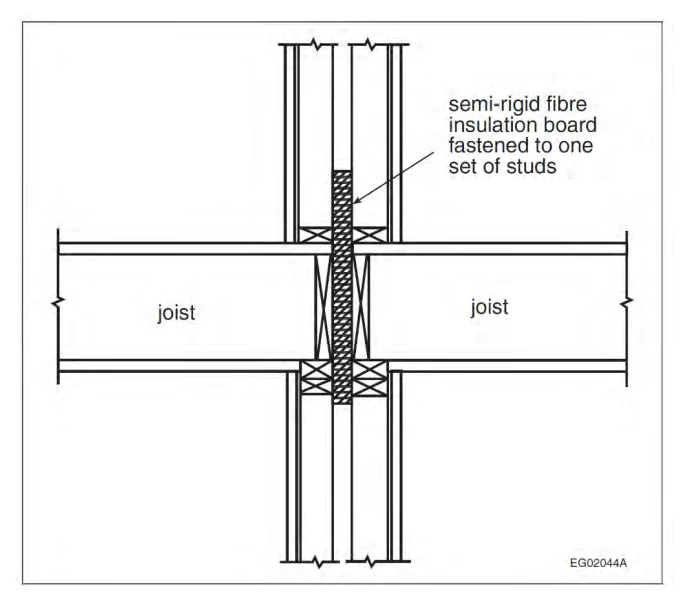
A-3.1.11.7.(8) Fire Blocks. Copy linkAdd bookmark
Figure A-3.1.11.7.(8) shows the location of the semi-rigid fibre insulation board at the intersection between walls and floors in wood-frame construction. The figure is intended to illustrate the fire block detail and not a design of a fire separation.
A-3.1.13.2.(2) Folding Partition. Copy linkAdd bookmark
Folding partitions used to divide a space into separate rooms are not considered as doors for the purposes of this Sentence.
A-3.1.15.1.(1) Roof Covering. Copy linkAdd bookmark
The tests described in CAN/ULC-S107 are intended to measure the relative fire-performance of roof coverings when exposed to a fire originating from sources outside the building. When metal deck or a similar noncombustible rigid roof surface is directly exposed to the exterior (a covering material on its exterior surface has not been provided), the requirements of this Sentence need not apply.
A-3.2.1.1.(3)(a) Mezzanine Area. Copy linkAdd bookmark
The permitted area of the mezzanine for the purposes of determining the allowable percentage is to be based on the open area of the floor of the space in which the mezzanine is located. The Code does not restrict the enclosing of space below the mezzanine, but the enclosed area must be deducted from the area of the overall space before applying the percentage allowance.
A-3.2.1.1.(8) Accessible Service Space. Copy linkAdd bookmark
These service spaces are often referred to as interstitial spaces and are designed to allow service personnel to enter and undertake maintenance or installation within the space. Catwalks or flooring are usually included to provide a walking or access surface. Even when flooring is included, it is not intended that the interstitial space should be considered as a storey for the purposes of the Code unless the space is used for purposes other than servicing or the storage of materials and equipment to be used for building services within that space.
A-3.2.2.2.(1) Special and Unusual Structures. Copy linkAdd bookmark
Examples of structures which cannot be identified with the descriptions of buildings in Articles 3.2.2.20. to 3.2.2.92. include grain elevators, refineries and towers. Publications that may be consulted to establish good engineering practice for the purposes of Article 3.2.2.2. include the NFPA Fire Protection Handbook, Factory Mutual Data Sheets, and publications of the Society for Fire Protection Engineering.
A-3.2.2.17.(1) Roof Assemblies in Gymnasiums, Swimming Pools, Arenas and Rinks. Copy linkAdd bookmark
The permission to waive the fire-resistance rating requirements for roof assemblies over gymnasiums, swimming pools, arenas and rinks that meet the conditions of Sentence 3.2.2.17.(1) includes the permission to waive the requirements relating to minimum size and construction details stated in Article 3.1.4.7. for wood elements in roof assemblies of heavy timber construction on buildings conforming to Articles 3.2.2.25. and 3.2.2.32. However, wood elements in roof assemblies of heavy timber construction on buildings conforming to Article 3.2.2.30. must nevertheless meet the requirements of Article 3.1.4.7.
A-3.2.2.18.(2) Sprinkler Extent. Copy linkAdd bookmark
A literal interpretation of Article 3.2.2.6. and Sentences 3.2.2.4.(1) and (2) could require installation of an automatic sprinkler system throughout all storeys of a building regardless of options in Articles 3.2.2.20. to 3.2.2.92. to construct one or more storeys without installation of sprinklers. It is the intent of the Code that all storeys below a storey in which an automatic sprinkler system is installed should also be protected by an automatic sprinkler system to ensure that a fire in a lower storey does not incapacitate the automatic sprinkler system or overwhelm an automatic sprinkler system in an upper storey. Persons in an upper storey in which waivers or reductions of other fire safety systems are permitted would be exposed to an increased risk from a fire on a lower storey. This concept also applies to situations in which an automatic sprinkler system has been installed within a floor area in order to modify other safety requirements applying within the floor area. If the uppermost storey or storeys of a building can be constructed without the installation of an automatic sprinkler system it is not necessary that an automatic sprinkler system required in a lower storey be extended into the upper storey or storeys.
A-3.2.2.35.(4) Sprinkler Requirements. Copy linkAdd bookmark
Spaces in a building of Group A, Division 4 occupancy that are intended to be equipped with sprinklers include, but are not limited to, dressing and changing rooms, concession stands and areas, toilet rooms, locker rooms, storage areas, service rooms, offices and other spaces that provide service to the building. The enclosure of seating areas with glazing needs special consideration in determining the requirements for sprinklers. For example, if the enclosed area is used for the consumption of food and beverages, it should be classified as Group A, Division 2 and the appropriate requirements of that classification applied. Enclosure of limited spaces above seating areas for press and media purposes is not considered to require the installation of sprinklers.
A-3.2.2.48.(4) and 3.2.2.57.(3) Occupancy Combinations in Buildings of Mixed Construction. Copy linkAdd bookmark
Buildings conforming to the building height and area limits and the other fire protection requirements of Article 3.2.2.48. or 3.2.2.57. may be entirely constructed of encapsulated mass timber construction and incorporate the occupancies specifically permitted by Sentence 3.2.2.48.(4) or 3.2.2.57.(3): e.g., Group A, Division 2 major occupancies on the first to third storeys, Group E major occupancies on the first and second storeys, and a parking garage on the first to fourth storeys.
Alternatively, the requirements of Articles 3.2.2.4. to 3.2.2.8. for superimposed major occupancies can be applied, resulting in buildings of mixed construction conforming to the building height and area limits for encapsulated mass timber construction and in which the lower storeys are of noncombustible construction and the upper storeys are of encapsulated mass timber construction. For example, a Group A, Division 2 or Group B, Division 3 major occupancy could be located on the first 4 storeys of a 12-storey Group C building constructed in accordance with Article 3.2.2.48., as long as these first 4 storeys were constructed of noncombustible construction in accordance with Article 3.2.2.23. or 3.2.2.38., as applicable. (See also Articles 3.2.2.6. and 3.2.2.7.)
A-3.2.2.51.(5) and 3.2.2.60.(4) Occupancy Combinations in Buildings of Mixed Construction. Copy linkAdd bookmark
Buildings conforming to the building height and area limits and the other fire protection requirements of Article 3.2.2.51. or 3.2.2.60. may be entirely constructed of combustible construction and incorporate the occupancies specifically permitted by Sentence 3.2.2.51.(5) or 3.2.2.60.(4): e.g., Group A, Division 2 and Group E major occupancies on the first and second storeys, and a parking garage on the first to third storeys.
Alternatively, the requirements of Articles 3.2.2.4. to 3.2.2.8. for superimposed major occupancies can be applied, resulting in buildings of mixed construction conforming to the building height and area limits of Article 3.2.2.51. or 3.2.2.60. and in which the lower storeys are of noncombustible construction and the upper storeys are of combustible construction. For example, a Group A, Division 2 or Group B, Division 3 major occupancy could be located on the first 4 storeys of a 6-storey Group C building constructed in accordance with Article 3.2.2.51., as long as these first 4 storeys were constructed of noncombustible construction in accordance with Article 3.2.2.23. or 3.2.2.38., as applicable. (See also Articles 3.2.2.6. and 3.2.2.7.)
A-3.2.3. Fire Protection Related to Limiting Distance Versus Separation Between Buildings. Copy linkAdd bookmark
Building Code provisions that address protection against fire spread from building to building use the limiting distance (see definition in Article 1.4.1.2. of Division A) for a building rather than using the distance between adjacent buildings on separate properties, since this would result in situations where the design and construction of a building on one property affects the design and construction of a building on an adjacent property.
The Code requirements that deal with reducing the probability of building-to-building fire spread were originally developed based on the assumption that the exposing building faces of adjacent buildings are of similar size and configuration, and are equidistant from the shared property line. Where buildings are of different sizes, the smaller building may be subject to a higher heat flux in the event of a fire compared to the larger building. Where buildings are closely spaced and not equidistant from the property line, the construction of the building with the greater limiting distance does not recognize the proximity of the building with the lesser limiting distance.
The Building Code has more stringent requirements for buildings having lesser limiting distance with regards to the maximum area and spacing of unprotected openings, and the construction, cladding and fire resistance of walls. This increased stringency recognizes that the fire hazard is greater where the buildings are close together and that adjacent buildings may have exposing building faces of different sizes, configurations or limiting distances, which could further increase the hazard.
The authority having jurisdiction may also address limiting distances through legal agreements with the parties involved that stipulate that the limiting distance be measured to a line that is not the property line. Such agreements would normally be registered with the titles of both properties.
A-3.2.3.1.(4) Spatial Separation Design. Copy linkAdd bookmark
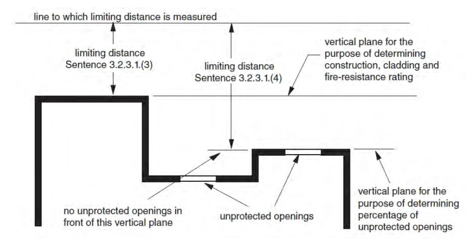
In the application of Sentences 3.2.3.1.(3) and (4), it is intended that Sentence (3) be used first to establish the basic requirements for the exterior wall in terms of fire-resistance rating, type of construction and type of cladding. The percentage of unprotected openings determined from the application of Sentence (3) would be unnecessarily restrictive if the actual unprotected openings occur in a plane that is set back from the front of the building face.
Sentence (4) applies to the calculation of the allowable percentage of unprotected openings based upon projection onto a plane that is in front of all unprotected openings. The application of these two Sentences is shown in Figure A-3.2.3.1.(4). The modifications permitted by Article 3.2.3.12. would be applied, if applicable, to the area of unprotected openings derived from Sentence (4).
A-3.2.3.6.(2) Protection of Roof Soffits Near Property Lines. Copy linkAdd bookmark
Sentences 3.2.3.6.(2) to (5) provide requirements for the protection of soffits where the soffit of the subject building is located close to the property line or to an imaginary line between two buildings on the same property. Fire from inside the roof space of the subject building can exit unprotected soffits and expose the adjacent building to flames.
A-3.2.3.7.(4)(d)(iv) Thickness of Cladding. Copy linkAdd bookmark
In the case of insulated vinyl siding, the maximum 2 mm thickness stated in Subclause 3.2.3.7.(4)(d)(iv) refers to the total thickness of the siding and the insulation, not of the siding alone.
A-3.2.3.12.(1) Increased Openings Permitted. Copy linkAdd bookmark
No increase of the maximum area of unprotected openings in an exposing building face should be applied until the requirements of Article 3.2.3.7. have been satisfied in determining the construction of the exposing building face.
A-3.2.3.14. Wall Exposed to Another Wall. Copy linkAdd bookmark
The intent of this Article is to ensure that the control of fire spread by the interior fire separations between adjacent fire compartments is not defeated through the spread of fire by thermal radiation outside the building. Minimum separations (Do) are specified between unprotected openings in separate fire compartments of the building where the exterior faces of these compartments are deemed to expose each other to a thermal radiation hazard. This situation may arise where the angle, θ, between the intersecting planes of the exposing building faces is less than 135° and both of these faces have unprotected openings. The exterior walls of the fire compartments do not have to intersect in order to apply Article 3.2.3.14. Rather, the critical factor is the angle, θ, between the planes formed by the exterior walls. Examples are shown in Figures A-3.2.3.14.-A, A-3.2.3.14.-B and A-3.2.3.14.-C of situations which would be addressed by this Article.
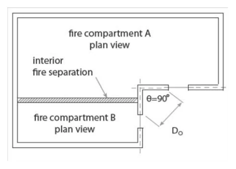
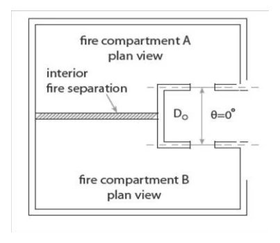
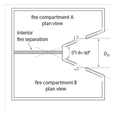
The exterior unprotected openings in the fire compartments are not deemed to expose each other to a thermal radiation hazard if:
- the angle formed between the planes of the exposing building faces is 135° or more, or
- the fire compartments are sprinklered.
In order to apply Sentence 3.2.3.14.(1), both of the exterior walls must have unprotected openings. Sentence (1) does not apply where the exterior wall of only one fire compartment has unprotected openings. The separation of exterior unprotected openings in adjacent fire compartments is not required if the openings in both compartments are in the same plane (θ = 180°).
Sentence 3.2.3.14.(2) requires the exterior walls of each fire compartment within the distance, Do to have a fire-resistance rating. The fire-resistance rating must be at least equal to the required interior separation between the fire compartments. Thermal radiation from an opening is substantially reduced at angles less than 45° from the plane of the unprotected opening. This may be shown schematically in Figure A-3.2.3.14.-D.:
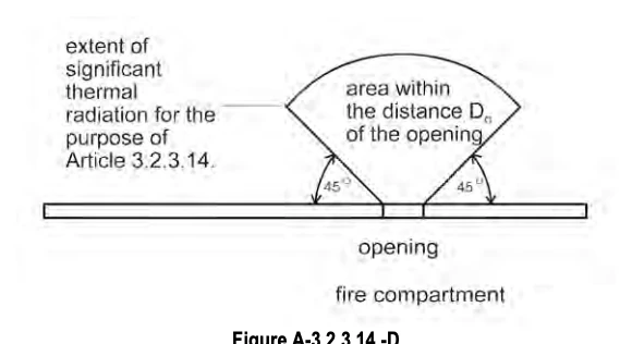
Sentence 3.2.3.14.(2) requires the portion of an exterior wall (containing an unprotected opening) of any other fire compartment that falls within the shaded area of the Figure above to have a fire-resistance rating.
Figure A-3.2.3.14-E illustrates the application of Sentence 3.2.3.14.(2) where the exterior walls of 2 fire compartments contain unprotected openings and the planes of the openings meet at 90°.
In order to apply Sentence 3.2.3.14.(2), the fire-resistance rating of each of the exterior walls exposed to significant thermal radiation at all angles of less than 135° within the distance, Do, from the opening in the opposite wall must be investigated.
In the example shown in Figure A-3.2.3.14.-E, the effect of Opening A on the exterior wall of Fire Compartment “B” must be investigated as follows.
In this example, a portion of the exterior wall of Fire Compartment “B” happens to fall within the distance, Do, and within the angle, θ less than 135°. However, only that part of the wall which is shown shaded is required to have a fire-resistance rating.
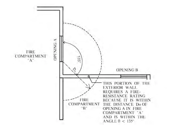
A-3.2.4. Fire Alarm System. Copy linkAdd bookmark
The term “fire alarm system” used in this Subsection applies to fire alarm systems with or without voice communication capability.
A-3.2.4.4.(1) Single-Stage Fire Alarm System. Copy linkAdd bookmark
This requirement, in combination with Article 3.2.4.22., is intended to allow for the provision of voice communication capability as an integral part of a single-stage fire alarm system.
A-3.2.4.4.(2) Two-Stage Fire Alarm System. Copy linkAdd bookmark
This requirement, in combination with Article 3.2.4.22. or 3.2.4.23., is intended to allow for the provision of voice communication capability as an integral part of a 2-stage fire alarm system.
A-3.2.4.4.(2)(c) Fire Alarm Alert Signal. Copy linkAdd bookmark
In a 2-stage fire alarm system described in Sentence 3.2.4.4.(2), the alert signal may be transmitted to audible signal devices in designated locations or to audible signal devices throughout the building. If actuated, the second stage alarm signal in a 2-stage fire alarm system may sound throughout all zones in the building. All manual station key switches would typically initiate the alarm signal.
Sentence 3.2.4.4.(2) also allows the implementation of a “zoned 2-stage” sequence of operation, whereby the alarm signal sounds in the zone of key switch actuation (and perhaps in the adjacent zones, which may be the storey above and the storey below) and the alert signal sounds throughout the rest of the building. This sequencing would be created automatically by the fire alarm control unit.
The key or special device referred to in Clause 3.2.4.4.(2)(c) should be immediately available to all persons on duty who have been given authority to sound an alarm signal.
A-3.2.4.6.(2) Access to Silencing Switches. Copy linkAdd bookmark
This requirement is intended to prevent unauthorized access to silencing switches. The satisfactory operation of a fire alarm system to alert the occupants of a building to an emergency is predicated on the assumption that the alarm signal will be silenced only after responsible staff have verified that no emergency exists.
A-3.2.4.7.(4) Design and Installation of Fire Department Notification. Copy linkAdd bookmark
In some jurisdictions, the fire department may utilize, or have available, a municipal fire alarm system or equipment intended for receiving notification by means of a direct connection. If used, it is expected that these systems and installations conform to the requirements of Sentence (4) so as to achieve and provide a uniform and reliable level of service. It is also intended that a proprietary central station as well as a fire brigade used by a large corporation, university campus or similar site comply with Sentence (4).
CAN/ULC-S561, “Standard for Installation and Services for Fire Signal Receiving Centres and Systems” which is referenced in Sentence 3.2.4.7.(4), and CAN/ULCS524, “Standard for Installation of Fire Alarm Systems” which is referenced in Sentence 3.2.4.5.(1), go hand-in-hand: conformity to CAN/ULC-S561 entails conformity with the fire alarm system components required in that standard, which include the fire alarm transmitter (signal transmitting unit), the interconnections, and the communication path.
A-3.2.4.7.(5)(b) Emergency Telephone Number. Copy linkAdd bookmark
In many municipalities an emergency telephone number, for example 911, is used for all emergency services and it is preferable to post that number.
A-3.2.4.8.(2) Fire Alarm Zones. Copy linkAdd bookmark
Alarm initiating devices referred to in this Sentence include fire detectors, waterflow switches and manual pull stations. If a room or space in a building extends through more than one storey of the building, as in the case of multi-level dwelling units and machinery rooms, judgment must be exercised in the zoning and annunciation of the fire detectors in that room or space. In general, the lowest storey on which access is provided into the room or space should be indicated on the annunciator to avoid unnecessary delays for the responding fire fighters. Consideration should also be given to the use of numbers or letters on the annunciator that correspond to those used in the building elevators.
A-3.2.4.8.(7) Indicator Devices. Copy linkAdd bookmark
It is permissible to install the fire alarm control unit in close proximity to the building entrance to meet the requirement for an annunciator. All signals required for the annunciator must be present at the control unit. In systems that include both control unit and annunciator, the signals must be routed to the annunciator through the control unit and the same functionality must be available at the control unit for operation and maintenance functions.
A-3.2.4.9.(3)(f) Supervision for Fire Pumps. Copy linkAdd bookmark
Specific electrical supervision for fire pumps is stated in NFPA 20, “Standard for the Installation of Stationary Pumps for Fire Protection”, which is referenced in NFPA 13, “Standard for the Installation of Sprinkler Systems”.
A-3.2.4.11.(1) Smoke Detector Location. Copy linkAdd bookmark
In the design and installation of the smoke detection system, consideration must be given to all features which could have a bearing on the location and sensitivity of the detectors, including ceiling height, sloped ceilings, diffusion from air conditioning and ventilating currents, obstructions, baffles, and other pertinent physical configurations that might interfere with the proper operation of the system.
A-3.2.4.11.(3) Visible Signals. Copy linkAdd bookmark
If staff located in each zone or compartment can see each sleeping room door, visible signals may be located above each door. If staff cannot see every door, it is intended that the visible signals be provided at the location where the staff are normally in attendance. The audible signal is intended to alert staff of the need to check the visible signals.
A-3.2.4.16.(1) Manual Station. Copy linkAdd bookmark
Only one manual station need be provided near a group of doors serving as a principal entrance or as a single exit facility.
A-3.2.4.18. Acoustic Measurement and Terminology. Copy linkAdd bookmark
The following notes on acoustic measurement and terminology are intended to assist in the application of the requirements for audibility of fire alarm system sounding devices.
The background or ambient measurement should be a spatial averaged A-weighted equivalent sound level measured for 60 s. This can be obtained using an integrating sound level meter with the integration time set to 60 s. During the measurement period the meter should be slowly moved about so as to sample the space uniformly but coming no closer than 0.5 m from any solid wall, floor or ceiling. Alternatively, measurements can be made at 3 or more positions throughout the space and an energy average calculated.
The measurement of the alarm level depends on the type of alarm signal. If the signal is a continuous signal from a bell or siren, the spatial averaged A-weighted equivalent sound level should be obtained. The integration time should be long enough to obtain a reasonable spatial average of the space, but not less than 10 s.
If the alarm has a temporal pattern, then the A-weighted sound level should be measured using the ‘fast’ time constant during the ‘on’ part of the cycle. In this situation it is not appropriate to use an integrating sound level meter. Since the duty cycle of the alarm is only 37.5% at best, that type of meter would give a reading that is 4 or more decibels lower than the level while the alarm is ‘on’. A number of measurements should be made about the space in question and the average value used to obtain a good spatial representation. Strictly speaking, the energy average of the measurements should be used; however, the frequency spectrum associated with most alarms is of a type that should give little variation about the space. If the measured levels don’t vary by more than 2 to 3 dB, then an arithmetic average rather than an energy average can be used.
Effect of FurnishingsCopy linkAdd bookmark
The final inspection of a fire alarm system is seldom made when the building is furnished and ready for occupancy. This results in measured levels which may be several decibels higher than will be found in the occupied building. The importance of this difference depends on the situation.
If the building is complete except for furnishings, so that the sources of ambient noise are present, then the amount by which the alarm signal exceeds the ambient level will not change appreciably with the introduction of furnishings. In this case both levels will be reduced by about the same amount.
If the primary source of ambient noise will be office equipment and workers, as would be expected in an open plan office, then measurements made prior to occupancy may differ substantially from those made afterwards. This may be true for both the absolute sound levels and the difference between the alarm level and the ambient.
A problem arises in trying to estimate what the absolute sound levels will be after the building is occupied.
In general, if the measurement is made in a totally bare room then the level will be about 3 dB higher than if the room were carpeted, assuming a reasonable carpet with an underlay. In most cases this will account for most of the absorption in the room and no further correction will be necessary. Adding heavy drapes and absorptive furnishings to a carpeted room can reduce the sound level by a further 2 to 3 dB.
Commercial buildings are more problematic. For example, if an open plan office is measured before any office screens are installed, there could be a substantial difference in the before and after levels, depending on the distance to the nearest alarm device.
Glossary of Acoustical TermsCopy linkAdd bookmark
Audible: A signal is usually considered to be clearly audible if the A-weighted sound level exceeds the level of ambient noise by 15 dB or more.
Awakening threshold: The level of sound that will awaken a sleeping subject 50% of the time.
A-weighted: A frequency weighting network which emphasizes the middle frequency components similar to the response of the human ear. The A-weighted sound level correlates well with subjective assessment of the disturbing effects of sounds. The quantity is expressed in dBA.
Masked threshold: The level of sound at which a signal is just audible in ambient noise.
Sound level: A sound pressure level obtained using a signal to which a standard frequency-weighting has been applied. Sound pressure: A fluctuating pressure superimposed on the static pressure by the presence of sound. The unqualified term means the root-mean-square sound pressure. In air, the static pressure is barometric pressure.
Sound pressure level: Ten times the common logarithm of the ratio of the square of the sound pressure under consideration to the square of the standard reference pressure of 20 mPa. The quantity obtained is expressed in decibels.
A-3.2.4.18.(1) Alert and Alarm Signals. Copy linkAdd bookmark
Alert signals are part of a 2-stage fire alarm system. The intent of the first, alert, stage is to notify persons in authority of a potential threat to building occupants. In certain occupancies such as an emergency ward in a hospital, it may not be desirable for an alert signal to sound throughout the floor area. In such cases, the alert signal may be restricted to a continuously staffed location. Examples of continuously staffed locations include a nursing station in a hospital or a building security desk in an office tower, where staff on shift are available every day and at all times.
A-3.2.4.18.(2) Alarm Signal Temporal Pattern. Copy linkAdd bookmark
The temporal pattern of an alarm signal relates to the time during which the signal is produced and the intervals between the individual signal pulses. The international standard ISO 8201, “Acoustics - Audible Emergency Evacuation Signal”, includes a pattern that is becoming widely used in different countries and it is appropriate for this pattern to be adopted in Canada. The temporal pattern can be produced on most signalling devices. Most existing alarm systems can be modified, and this pattern could be phased in when the systems require modification. The characteristic of the pattern is a 3-pulse phase followed by an off phase. The 3 pulses each consist of an on phase lasting for 0.5 ± 0.05 s followed by an off phase lasting for 0.5 ± 0.05 s sounded for 3 successive on periods and then followed by an off phase lasting for 1.5 ± 0.15 s. Figure A-3.2.4.18.(2)-A indicates the pattern that is intended.
Although the diagram shows a square wave form, the wave can have other shapes that produce a similar effect.
If single stroke bells are to be used, the temporal pattern can be produced by having the bell struck three times at a rate of one stroke per second followed by an interval of 2 s of silence. Figure A-3.2.4.18.(2)-B shows the pattern that results.
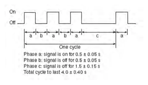
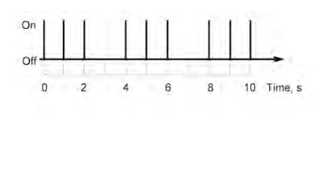
Note:
A-3.2.4.18.(3) Audibility of Alarm Systems. Copy linkAdd bookmark
It is very difficult to specify exactly what types of sound patterns are considered to be “significantly different” from one another. The intent is to ensure that there is a noticeable or measurable difference between the alert signals and the alarm signals such that it reduces the possibility of confusion.
A-3.2.4.18.(4) Sound Pressure Level. Copy linkAdd bookmark
For the purposes of this requirement, an audible signalling device should not produce a sound pressure level more than 110 dBA when measured at a distance of 3 m.
A-3.2.4.18.(5) Residential Sound Level. Copy linkAdd bookmark
In a building in which corridors or hallways serve more than one suite or dwelling unit, there will be situations in which an audible signal device cannot be placed in the corridor or hallway to alert persons sleeping in suites and dwelling units, because the sound level in the vicinity of the device would exceed that permitted by Sentence 3.2.4.18.(4).
In these situations it will be necessary to supplement the building fire alarm system with an audible signal device in the suite or dwelling unit. These devices could be piezoelectric devices similar to the sounding units in many smoke alarms, subject to the device emitting the appropriate temporal pattern required by Sentence 3.2.4.18.(2).
The sound pressure level required in this Sentence should be measured when the suite is unfurnished and unoccupied.
A-3.2.4.18.(6) Low Frequency Signal. Copy linkAdd bookmark
Audible signal devices that emit a low frequency signal in the range of 470 Hz to 570 Hz have been shown to be more effective in waking people.
A-3.2.4.18.(8) Disconnect Device for Dwelling Units. Copy linkAdd bookmark
In order to minimize the annoyance caused by false and unwanted alarms, the disconnect is intended to permit a person to silence the local audible device within the dwelling unit. At that time the person would be aware of sounds from devices in common spaces and could plan appropriate action.
A-3.2.4.18.(9) and (10) Signal Circuits. Copy linkAdd bookmark
Clause 3.2.4.18.(9)(a) permits Class A wiring, or Class B wiring with signal circuit isolators located outside of the suites, to serve audible signal devices within residential suites. Clause 3.2.4.18.(9)(b) permits a separate signal circuit to serve each suite without the need for signal circuit isolators or Class A wiring. Open circuits and Class A and Class B wiring circuits are terms defined in CAN/ULC-S524, “Standard for Installation of Fire Alarm Systems."
A-3.2.4.18.(12) Separate Signal Circuits. Copy linkAdd bookmark
Sentence 3.2.4.18.(9) in combination with Sentence 3.2.4.18.(10) require separate audible signal circuits for dwelling units. It allows the designer the option to wire the audible signal devices in a dwelling unit on an individual circuit that serves each suite only or to wire the audible signal devices in a common circuit that serves the dwelling units within the floor area and is separate from the circuit that serves the audible devices outside the dwelling unit. Compliance with either of the above two options would meet the intent of a separate circuit required in Sentence 3.2.4.18.(12).
A-3.2.4.19.(1)(g) Visible Signal in Hotels and Motels. Copy linkAdd bookmark
Visible signal devices should be installed in a combination of regular suites and designated accessible suites in hotels and motels so that people who are deaf or hard of hearing can safely occupy either type of suite.
Visible signal devices are not required to be installed in all the rooms of the suite. The signal should be visible from any room in the suite, which can be accomplished by installing glazing panels between the rooms or additional visible signal devices.
In addition, CAN/ULC-S524, “Standard for Installation of Fire Alarm Systems,” requires that high-intensity strobes be used in sleeping rooms.
A-3.2.4.19.(2) Visible Signal. Copy linkAdd bookmark
If staff located in each zone or compartment can see each sleeping room door, visual signals could be located above each door. If staff cannot see every door, it is intended that the visual signals be provided at the location where the staff are normally in attendance.
A-3.2.4.19.(3) Visible Alarm Pattern. Copy linkAdd bookmark
CAN/ULC-S526, “Visible Signal Devices for Fire Alarm Systems Including Accessories”, published by Underwriters’ Laboratories of Canada, applies to visible signalling units. This document is referenced by the most recent standard for the installation of fire alarm systems and would automatically apply. Current Canadian technology does not integrate visible and audible alarms to have the same temporal pattern. Visible and audible alarms should have as close a temporal pattern as possible but without interference beats that might have a deleterious effect on some persons. Visible signalling devices with the same temporal pattern as required for audible devices are available from some sources and they should become available in Canada. Not all units that comply with the ULC standard will have sufficient power to adequately cover large areas; care will have to be taken to specify units with adequate power when large spaces are being designed.
A-3.2.4.20.(9) Smoke Alarm Installation. Copy linkAdd bookmark
Ontario’s Electrical Safety Code permits a smoke alarm to be installed on most residential circuits that carry lighting outlets and receptacles. It is the intent of the Building Code that any other item on a circuit with a smoke alarm should be unlikely to be overloaded and trip the breaker with a resultant loss of power that is not sufficiently annoying for the breaker to be restored to the on position. It is considered that an interior bathroom light or a kitchen light fulfills this intent, but that circuits restricted to receptacles do not fulfill this intent.
A-3.2.4.20.(10) Smoke Detectors in Lieu of Smoke Alarms. Copy linkAdd bookmark
It is intended that the smoke detector in this application will function as per the requirements of a smoke alarm; specifically, it will be a localized alarm to the suite. The advantage of this type of installation is that the detector would be monitored by the fire alarm panel, which would provide notification to the supervisory personnel and be inspected as per CAN/ULC-S524, “Standard for Installation of Fire Alarm Systems.” It is not intended that smoke detectors used in lieu of smoke alarms will activate the fire alarm panel to send a signal to the fire department.
A-3.2.4.20.(17) Smoke Alarms with a Visual Signalling Component. Copy linkAdd bookmark
Smoke alarms with a visual signaling component can alert people who are deaf, deafened or hard of hearing to the presence of smoke in the dwelling just as the alarm sound provides an alert to people with no or low vision or who are sighted. The visual signal provides an extra level of safety alerts to building residents.
A-3.2.4.22.(1)(b) Voice Messages. Copy linkAdd bookmark
The concept of intelligibility expressed in Clause 3.2.4.22.(1)(b) is intended to mean that a person with average hearing and cognitive abilities is able to understand the messages that are transmitted into the space occupied by the person. There is no absolute measure to predetermine the effect of loudspeakers and it maybe necessary, once the building has been furnished and occupied, to increase to the number of loudspeakers to improve the quality of the messages.
The intelligibility of the message depends on the speech level, the background level, and the reverberation time of the space. ISO 7731, “Ergonomics - Danger Signals for Public and Work Areas - Auditory Danger Signals”, addresses audibility. The standard suggests that an A-weighted sound level at least 15 dBA above the ambient is required for audibility, but allows for more precise calculations using octave or ⅓ octave band frequencies to tailor the alarm signal for particular ambient noise conditions. Design of the alarm system is limited to ensuring that all areas receive an adequately loud alarm signal.
If a public address system is to be used to convey instructions during an emergency, then the requirements of the system are less straightforward. In general, however, a larger number of speakers operating at lower sound levels would be required.
Additional guidance on how to design and evaluate the intelligibility of a communication system can be found in the following documents
- IEC 60268-16, Sound System Equipment — Part 16: Objective Rating of Speech Intelligibility by Speech Transmission Index
- ISO 7240-19, Fire Detection and Alarm Systems — Part 19: Design, Installation, “Commissioning and Service of Sound Systems for Emergency Purposes”
- NEMA SB 50, “Emergency Communications Audio Intelligibility Applications Guide”
- Annex D of NFPA 72, "National Fire Alarm and Signaling Code".
A-3.2.5.4.(1) Fire Department Access for Detention Buildings. Copy linkAdd bookmark
Buildings of Group B, Division 1 used for housing persons who are under restraint include security measures that would prevent normal access by local fire departments. These security measures include fencing around the building site, exterior walls without openings or openings which are either very small or fitted with bars, and doors that are equipped with security hardware that would prevent easy entry. These buildings would have firefighting equipment installed and the staff would be trained to handle any small incipient fires. It is expected that appropriate fire safety planning would be undertaken in conjunction with local fire departments in order that special emergencies could be handled in a cooperative manner.
A-3.2.5.6.(1) Fire Department Access Route. Copy linkAdd bookmark
The design and construction of fire department access routes involves the consideration of many variables, some of which are specified in the requirements in the Building Code. All these variables should be considered in relation to the type and size of fire department vehicles available in the municipality or area where the building will be constructed. It is appropriate, therefore, that the local fire department be consulted prior to the design and construction of access routes.
A-3.2.5.7. Water Supply. Copy linkAdd bookmark
This Article requires that an adequate water supply for firefighting is to be provided for every building. However, farm buildings of low human occupancy under the National Farm Building Code of Canada 1995 are exempted. The water supply requirements for interior fire suppression systems such as sprinkler systems and standpipe and hose systems are contained in other standards, for example, NFPA Standard 13, “Standard for the Installation of Sprinkler Systems”, and NFPA Standard 14, “Standard for the Installation of Standpipe and Hose Systems”. This Appendix note focuses only on water supplies that are considered essential to firefighting by fire department or other trained personnel using fire hoses.
Minimum requirements for water supply for firefighting are relevant mainly to building sites not serviced by municipal water supply systems. For building sites serviced by municipal water supply systems where the water supply duration is not a concern, water supply flow rates at minimum pressures would be the main focus of this Appendix note. However, where municipal water supply capacities are limited, it would be necessary for buildings to have on-site supplemental water supply.
An adequate water supply for firefighting should be an immediately available and accessible water supply with sufficient volume and/or flow to enable fire department personnel using fire hoses to control fire growth until the building is safely evacuated, prevent the fire from spreading to adjacent buildings, limit environmental impact of the fire, and provide a limited measure of property protection.
The sources of water supply for firefighting purposes may be natural or man-made. Natural sources may include ponds, lakes, rivers, streams, bays, creeks, springs, artesian wells, and irrigation canals. Man-made sources may include aboveground tanks, elevated gravity tanks, cisterns, swimming pools, wells, reservoirs, aqueducts, tankers, and hydrants served by a public or private water system. It is imperative that such sources of water be accessible to fire department equipment under all climate conditions.
The available water supply would allow arriving fire department personnel to use the water at their discretion when entering a burning building with hose lines. During the search and evacuation operation, hose streams may be needed for fire suppression to limit fire spread. The duration of the water supply should be sufficient to allow complete search and evacuation of the building. Once the search and rescue operations are complete, additional water may be required for exposure protection or fire suppression to limit property damage.
Fire departments serving remote or rural areas often have to respond to a fire with a transportable water supply of sufficient volume for approximately 5 to 10 minutes when using one or two 38 mm hose lines. This would provide minimal hose streams allowing immediate search and rescue operations in small buildings with simple layouts but limited fire suppression capabilities, especially if a fire is already well-established.
For larger more complex buildings, an on-site water supply for firefighting would be needed to provide an extended duration of hose stream use by the fire department to allow search and evacuation of the building, exposure protection and fire suppression. The volume of this on-site water supply would be dependent on the building size, construction, occupancy, exposure and environmental impact potential, and should be sufficient to allow at least 30 minutes of fire department hose stream use.
The recommendations of this Appendix note are predicated on prompt response by a well-equipped fire department using modern firefighting techniques, and buildings being evacuated in accordance with established building fire safety plans and fire department pre-fire plans. For buildings constructed in areas where fire department response is not expected at all or in a reasonable time, sprinkler protection should be considered to ensure safe evacuation.
Elementary and secondary schools usually have a record of well-established and practiced fire safety plans which would allow complete evacuations within 4 minutes. Because of this and the inherent high level of supervision in these buildings, a reduction of the water supply for firefighting may be considered. It is suggested that the level of reduction should be determined by the local enforcement authority based on the resources and response time of the fire department, and the size and complexity of the buildings.
When designing open, unheated reservoirs as sources of fire protection water, a 600 mm ice depth allowance should be included in the water volume calculations, except where local winter temperature conditions result in a greater ice depth (as typically found on local lakes or ponds). As well, make-up water supplies should be provided to maintain the design volumes, taking into account volume loss due to evaporation during drought periods.
- Buildings not Requiring an On-Site Water Supply
- (a) A building would not require an on-site water supply for firefighting if the building satisfies the criteria set out in Item 1(b) or Item 1(c) provided that:
- (i) the building is serviced by a municipal water supply system that satisfies Item 3(b), or
- (ii) the fire department can respond with a transportable water supply of sufficient quantity to allow them to conduct an effective search and evacuation of the building, determined on the basis of other guidelines or standards (such as, NFPA 1142, “Standard on Water Supplies for Suburban and Rural Fire Fighting”).
- (b) A building would not require an on-site water supply for firefighting where all of the following criteria are met:
- (i) the building area is 200 m2 or less,
- (ii) the building height is 2 storeys or less,
- (iii) the building does not contain a care or detention occupancy,
- (iv) the building does not require a sprinkler system or a standpipe and hose system,
- (v) the limiting distance from the property line is at least 13 m if the building contains a high hazard industrial occupancy, and
- (vi) the building constitutes no significant environmental contamination potential due to fire.
- (c) A building that exceeds 200 m2 in building area or 2 storeys in building height and that contains a low hazard industrial occupancy may not require an on-site water supply for firefighting if the combustible loading in the building is insignificant (such as that found in cement plants, steel stock storage sheds, etc.), as determined by the chief building official.
- (a) A building would not require an on-site water supply for firefighting if the building satisfies the criteria set out in Item 1(b) or Item 1(c) provided that:
- Sprinklered Buildings For sprinklered buildings, water supply additional to that required by the sprinkler systems should be provided for firefighting using fire hoses in accordance with the hose stream demands and water supply durations for different hazard classifications as specified in NFPA 13, “Installation of Sprinkler Systems”.
- Buildings Requiring On-Site Water Supply
- (a) Except for sprinklered buildings and as required by Items 3(c) and 3(e), buildings should have a supply of water available for firefighting purposes not less than the quantity derived from the following formula: Q = K • V • Stot where
Q = minimum supply of water in litres
K = water supply coefficient from Table 1
V = total building volume in cubic metres
Stot = total of spatial coefficient values from property line exposures on all sides as obtained from the formula:
Stot = 1.0 + [Sside1 + Sside2 + Sside3 + ... etc.)] where
Sside values are established from Figure 1, as modified by Items 3(d) and 3(f), and
Stot need not exceed 2.0.
- (b) Water supply flow rates should not be less than that specified in Table 2. Where the water supply is from a municipal or industrial water supply system, the required flow rate should be available at a minimum pressure of 140 kPa.
- (c) The water supply as required in Item 3(a) should not be less than that needed to provide the minimum flow rate specified in Table 2 for a minimum duration of 30 minutes.
- (d) Where a masonry wall with a minimum fire-resistance rating of 2 h, and no unprotected openings is provided as an exterior wall, the spatial coefficient (Sside) for this side of the building may be considered equal to 0. This masonry wall should be provided with a minimum 150 mm parapet. Firewalls that divide a structure into two or more buildings may be given similar consideration when evaluating the exposure of the buildings to each other.
- (e) In elementary or secondary schools, the water supply determined in accordance with Items 3(a) and 3(b) may be reduced. The level of reduction to be applied would be at the discretion of the local enforcement authority, and should not exceed 30 percent.
- (f) The spatial coefficient Sside may be considered equal to 0 when the exposed building is on the same property and is less than 10 m2 in building area.
- Additions to Existing Buildings
- (a) Except as permitted in Items 4(b) and 4(c), additions to existing buildings should be provided with a water supply for firefighting as required in Items 3(a) to 3(e). Although under Part 11, Renovation, the required water supply is to be based only on the building volume of the addition, it is recommended that the entire building volume of the expanded facility be used to ensure complete evacuation and safety of all the occupants.
- (b) Buildings with new additions falling within any one of the following criteria would not require an additional water supply for firefighting where:
- (i) the expanded building complies with all the requirements of Item 1(a),
- (ii) the new addition does not exceed 100 m2 in building area, or
- (iii) the new addition exceeds 100 m2 but does not exceed 400 m2 in building area, contains an assembly, business and personal services, mercantile or low hazard industrial occupancy, is of noncombustible construction, does not result in a significant increase in exposure to other existing buildings, has no combustible storage or process, and is separated from the existing building by a fire separation with a fire-resistance rating of at least 1 h.
- (c) Where a firewall is provided between the new addition and the existing building, the water supply for firefighting may be determined in accordance with Items 1(a) and 3(a), using only the building volume of the new addition.
| Water Supply Coefficient - K | |||||
|---|---|---|---|---|---|
| Type of Construction | Classification by Group or Division in Accordance with Table 3.1.2.1. of the Building Code | ||||
| A-2 B-1 B-2 B-3 C D | A-4 F-3 | A-1 A-3 | E F-2 | F-1 | |
| Building is of noncombustible construction with fire separations and fire-resistance ratings provided in accordance with Subsection 3.2.2., including loadbearing walls, columns and arches. | 10 | 12 | 14 | 17 | 23 |
| Building is of noncombustible construction or of heavy timber construction conforming to Article 3.1.4.6. Floor assemblies are fire separations but with no fire-resistance rating. Roof assemblies, mezzanines, loadbearing walls, columns and arches do not have a fire-resistance rating. | 16 | 19 | 22 | 27 | 37 |
| Building is of combustible construction with fire separations and fire-resistance ratings provided in accordance with Subsection 3.2.2., including loadbearing walls, columns and arches. Noncombustible construction may be used in lieu of fire-resistance rating where permitted in Subsection 3.2.2. | 18 | 22 | 25 | 31 | 41 |
| Building is of combustible construction. Floor assemblies are fire separations but with no fire-resistance rating. Roof assemblies, mezzanines, loadbearing walls, columns and arches do not have a fire-resistance rating. | 23 | 28 | 32 | 39 | 53 |
| Part 3 Buildings under the Building Code | Required Minimum Water Supply Flow Rate, L/min |
|---|---|
| One-storey building with building area not exceeding 600 m² | 1 800 |
| All other buildings | 2 700 (if Q ≤ 108 000 L)(1) 3 600 (if Q > 108 000 L and ≤ 135 000 L)(1) 4 500 (if Q > 135 000 L and ≤ 162 000 L)(1) 5 400 (if Q > 162 000 L and ≤ 190 000 L)(1) 6 300 (if Q > 190 000 L and ≤ 270 000 L)(1) 9 000 (if Q > 270 000 L)(1) |
Notes to Table 2:
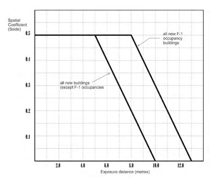
Further clarification of intent and sample problems and solutions are contained in the “Fire Protection Water Supply Guideline for Part 3 in the Ontario Building Code” (TG-03-1999). This guideline may be obtained through the Office of the Fire Marshal’s by contacting AskOFM@ontario.ca or contact a Field Advisory Services adviser toll free at 1-800-565-1842.
A-3.2.5.9.(4)(c) Fire Department Pumping Equipment. Copy linkAdd bookmark
Availability of appropriate pumping equipment from the local fire department or, in the case of industrial plants or complexes, from their fire brigade, is considered sufficient to meet the intent of this requirement.
A-3.2.5.11.(2) Hose Stations. Copy linkAdd bookmark
A building that is partially sprinklered may have some floor areas where local sprinklers are installed that do not cover the entire floor area. It is intended that hose stations be provided in these floor areas to allow emergency responders to fight fires that cannot be controlled by local sprinklers.
A-3.2.5.12.(1) Sprinkler System Design. Copy linkAdd bookmark
In NFPA 13, “Standard for the Installation of Sprinkler Systems”, reference is made to other NFPA standards which contain additional sprinkler design criteria. These criteria apply to industrial occupancies with high fire loads, including warehouses with high piled storage, and industrial occupancies intended for the use, manufacture or storage of highly flammable materials. Therefore, while only NFPA 13 is called up directly by Sentence 3.2.5.13.(1), the additional criteria in the other NFPA standards are included automatically.
In some NFPA standards, certain aspects of sprinkler protection are dependent on the fire-resistance rating of the vertical structural members. In these cases, the sprinkler system design options can be affected by the fire-resistance rating of these elements. For example, in buildings used for the storage of rubber tires, sprinklers directed at the sides of a column are required if the column does not have the required fire-resistance rating.
Other NFPA standards may require that certain occupancies be sprinklered in conformance with NFPA 13, as in the case of some garages. These requirements do not supersede the requirements in the Building Code. An occupancy is required to be sprinklered only when this is specified in the Building Code, but when it is so required, it must be sprinklered in conformance with NFPA 13 and its referenced standards.
Additionally, while Part 4 contains seismic force provisions that apply to the design of sprinklers, NFPA 13 contains other structural requirements for sprinklers that are also required to be met.
A-3.2.5.12.(2) Sprinklering of Residential Buildings Above a Storage Garage Considered as a Separate Building. Copy linkAdd bookmark
For the purpose of determining whether NFPA 13R, “Standard for the Installation of Sprinkler Systems in Residential Occupancies up to and including Four Stories in Height”, applies to a residential building constructed over a storage garage, it is not intended that a storage garage constructed as a separate building in accordance with Article 3.2.1.2. be considered as a storey when determining the building height of the residential building. Similarly, this would not preclude the use of NFPA 13D, “Installation of Sprinkler Systems in One- and Two-Family Dwellings and Manufactured Homes”, for any one- or two-family home constructed above such a storage garage.
A-3.2.5.12.(6) Sprinklering of Roof Assembly. Copy linkAdd bookmark
Sprinkler protection for roof assemblies in lieu of fire resistance is based on the assumption that the sprinklers will protect the roof assembly from the effects of fire in spaces below the roof. If a ceiling membrane is installed, the sprinklers would have to be located below the membrane in order to react quickly to the fire. In certain instances, however, sprinklers may be required within the concealed spaces as well as below the membrane. NFPA 13, “Standard for the Installation of Sprinkler Systems”, requires sprinklers in certain concealed spaces.
According to NFPA 13 and 13R, some small rooms and closets within a dwelling unit in a sprinklered building, including those that may be in the storey immediately below the roof assembly do not require sprinklers. However, the Building Code requires sprinkler protection within all rooms and closets immediately below the roof so as to control any fire that might start in that space and thereby limit the probability of the fire spreading into the roof assembly.
Moreover, NFPA 13D, “Standard for the Installation of Sprinkler Systems in One- and Two-Family Dwellings and Manufactured Homes,” also allows the omission of sprinklers in such rooms and closets under certain circumstances, provided the building is sprinklered in conformance with this standard. In this case, the Building Code concurs with the provisions of the NFPA 13D standard.
A-3.2.5.12.(7) Balconies and Decks. Copy linkAdd bookmark
The intent of this provision is to suppress or control the spread of a fire originating from a balcony or deck to the balcony above, roof assembly or other parts of the building. It is not intended to apply to a roof top deck or uppermost balcony where there are no parts of the building above.
A-3.2.5.12.(8) Sprinkler Rating. Copy linkAdd bookmark
The requirements of this Sentence can be met by using sprinklers with a rating of 79°C to 107°C.
A-3.2.5.13.(1) Hazard Classification for Sprinkler Selection. Copy linkAdd bookmark
The reference to light hazard occupancies is based on the descriptions of these occupancies given in NFPA 13, “Standard for the Installation of Sprinkler Systems” and is intended only for use in the design of sprinkler systems. These descriptions should not be confused with the occupancy classifications in the Building Code.
In NFPA 13 a light hazard occupancy is one in which the quantity or combustibility of contents is low and fires with relatively low rates of heat release are expected. Typical buildings or parts of buildings include: churches; clubs; eaves and overhangs, if of combustible construction with no combustibles beneath; educational buildings; hospitals; institutional buildings; libraries, except very large stack rooms; museums; long term care or convalescent homes; offices, including data processing rooms; residential buildings; restaurant seating areas; theatres and auditoria, excluding stages and proscenia; and unused attics.
Although NFPA 13R, “Standard for the Installation of Sprinkler Systems in Residential Occupancies up to and Including Four Stories in Height”, and NFPA 13D, “Standard for the Installation of Sprinkler Systems in One- and Two-Family Dwellings and Mobile Homes”, as referenced by NFPA 13, are concerned with specific types of residential occupancy, namely apartment buildings up to four storeys, one and two family dwellings, and mobile homes, for the purpose of acceptance of combustible sprinkler piping these occupancies are considered to be included in the category of residential buildings under light hazard occupancies.
A-3.2.5.18.(1) Fire Pumps. Copy linkAdd bookmark
In order to ensure an adequate water supply, it may be necessary to install a fire pump for a building that has either a standpipe system or an automatic sprinkler system installed. Reference to NFPA 20, “Standard for the Installation of Stationary Pumps for Fire Protection,” provides the necessary guidance to designers.
A-3.2.6. Smoke Control for High Buildings. Copy linkAdd bookmark
Experience with high buildings has shown that the time required for complete evacuation can exceed that which is considered necessary for the safe egress of all occupants. Studies of the “chimney effect” and observations of smoke movement in actual fires have shown that fire compartmentation to contain a fire on any one storey will not usually prevent the movement of smoke through elevator, stair and other vertical shafts to the upper floors of a high building. Occupants of a high building in which an automatic sprinkler system is not installed, and particularly those on upper storeys, could be faced with severe smoke conditions from fires occurring in storeys below them before their own evacuation is possible. The requirements of Subsection 3.2.6. are intended to maintain safe conditions for occupants of a high building who may have to remain in the building during a fire, and to assist the firefighters by providing efficient access to the fire floor. The Notes for Subsection 3.2.6. are intended to assist a designer in complying with the requirements of Subsection 3.2.6. The knowledge requirements are well within the capabilities of a competent designer. The designer should appreciate, however, that successful application requires a clear understanding of the principles that govern smoke movement. Subsection 3.2.6. contains only those items that relate to the design and construction of a building; operation of the facilities and recommended actions to be taken by the building owner, occupant and fire department are covered by the Fire Code.
The designer is cautioned that the tabular and graphical information in the Notes for Subsection 3.2.6. was developed for buildings having conventional configurations. The designer has to judge the extent to which the building under consideration has characteristics that will allow the application of this information; this is particularly true of designs employing air-handling systems for which a realistic assessment of the leakage characteristics of the enclosures of spaces may be critical.
It is assumed that buildings regulated by Subsection 3.2.6. will be in an area served by a fire department capable of an early response and that all firefighting and rescue situations will be under the direct control of the officer-in-charge of the fire department responding to the emergency. It is important that firefighters be provided with a smoke-free access to fire floors below grade. Provisions are included to separate exit stairways serving storeys above grade from those serving storeys below grade, and to limit entry of smoke into these shafts. Similarly, elevator hoistways and service shafts are required to be provided with a separation near grade or be designed to limit their functioning as paths of smoke movement into upper floor areas from storeys below grade.
It is assumed that in the event of fire, occupants of the floor on which the fire occurs will leave by exit stairs immediately following the sounding of a fire alarm, and that occupants of the floor immediately above the floor on which the fire occurs will be advised to leave by the first fire department officer on the scene or other person assigned this responsibility. Occupants of all other floors may remain on their floors unless otherwise directed. It is also assumed that the owner of the building has complied with the Emergency Planning Section of the Fire Code by preparing a comprehensive fire safety plan to safeguard the building occupants and that the building supervisory staff are familiar with the requirements of Subsection 3.2.6. and with their responsibilities under the fire safety plan.
The Building Code requires that a check be made of the smoke control and mechanical venting systems. Testing will indicate deficiencies caused by inexact estimates of the leakage characteristics or of air supply requirements and, in all but the most extreme cases, will provide an opportunity for appropriate adjustments before the system is put into service.
A-3.2.6.4.(6)(a) Elevator Recall. Copy linkAdd bookmark
Automatic emergency recall actuation that is dependent on the operation of 2 smoke detectors in the elevator lobby meets the intent of this requirement. Such an arrangement may reduce the frequency of nuisance recalls.
A-3.2.6.5.(6)(b) Protection of Electrical Conductors Copy linkAdd bookmark
Electrical conductors are part of a system that includes, among other components, raceways, conduits, splices, couplings, vertical supports, grounds and pulling lubricants. When selecting electrical conductors to provide a circuit integrity rating, it is important to understand how they will be installed and to know if the fire performance of the system as a whole was tested.
A-3.2.7.4.(1) Emergency Power Reliability. Copy linkAdd bookmark
In some areas power outages are frequent and may be of long duration. These local conditions should be taken into account in determining the type of system for supplying emergency power for lighting. This should be studied at the planning stage of a building project in conjunction with the local fire safety and building officials.
A-3.2.7.6.(1) Emergency Power for Hospitals. Copy linkAdd bookmark
CSA-Z32, “Electrical Safety and Essential Electrical Systems in Health Care Facilities”, contains requirements for three classes of health care facilities - Class A, Class B and Class C. The intent of Article 3.2.7.6. is to apply specific requirements for emergency equipment for Class A facilities, which are designated as hospitals by the authorities having jurisdiction and where patients are accommodated on the basis of medical need and are provided with continuing medical care and supporting diagnostic and therapeutic services.
A-3.2.7.8.(3) Emergency Power Duration. Copy linkAdd bookmark
The times indicated in this Sentence are the durations for which emergency power must be available for a building under fire emergency conditions. Additional fuel for generators or additional battery capacity is required to handle normal testing of the equipment. If the operation of emergency generators or batteries is intended for other than fire emergency conditions, such as power failures, fuel supplies or battery capacity must be increased to compensate for that use.
A-3.2.7.9.(1) Emergency Power Reliability. Copy linkAdd bookmark
In some areas power outages are frequent and may be of long duration. These local conditions should be taken into account in determining the type of system for supplying emergency power for building services. This should be studied at the planning stage of a building project in conjunction with the local fire safety and building officials.
A-3.2.7.10.(2)(a) and (3)(a) Protection of Electrical Conductors. Copy linkAdd bookmark
It is important to understand that electrical conductors are part of a system that includes—among other components— raceways, conduits, splices, couplings, vertical supports, grounds and pulling lubricants. When selecting electrical conductors to provide a circuit integrity rating, it is therefore important to understand how they will be installed and to know if the fire performance of the system as a whole was tested.
A-3.2.7.10.(5)(b) Electrical Conductors in the Same Room. Copy linkAdd bookmark
If the distribution panel and the equipment it serves are within the same room, only the electrical conductors leading up to the distribution panel need to be protected. It is assumed that the distribution panel and the equipment it serves are within sufficient proximity to each other such that a fire in the same area of origin would affect both.
A-3.2.7.10.(7) Fire Alarm Branch Circuits. Copy linkAdd bookmark
In order to ensure continuous operation of the fire alarm and voice communication system in a high-rise building for a sufficient duration of time to control and direct the evacuation of building occupants, a level of protection is required by Sentence 3.2.7.10.(2) for those electrical conductors interconnecting the major elements of the fire alarm system. Sentence 3.2.7.10.(7) permits the protection of electrical conductors to be waived for portions connecting a transponder or fault isolation device to the fire alarm input devices (fire detectors, manual stations, etc.) or a voice communication transponder to a fire alarm audible signalling device, provided all circuits or portions of the circuits are contained within the same storey.
A-3.2.8.2.(3) Special Protection of Opening. Copy linkAdd bookmark
In manufacturing operations involving the use of conveyor systems to transport material through fire separations, it may not be possible to use standard closure devices. NFPA 80, “Standard for Fire Doors and Other Opening Protectives”, includes appendix information concerning protection of openings through vertical fire separations. NFPA 13, “Standard for the Installation of Sprinkler Systems”, includes methods of protecting openings through floor assemblies, however, it is assumed by that standard that the remainder of the building would be sprinklered. Combinations of methods may be required to ensure that the level of safety inherent in the requirements of the Code is maintained.
A-3.2.8.2.(6)(b) Restriction on Size of Openings Through Floors. Copy linkAdd bookmark
The phrase “used only for stairways, escalators or moving walks” is intended to restrict the size of a floor opening to what is necessary to accommodate the stairway, escalator or moving walk.
A-3.2.8.2.(6)(c) Waiver of Occupancy Separation Continuity. Copy linkAdd bookmark
The typical application of this Sentence is to buildings with a mixture of occupancies that are randomly located throughout the building. Examples include shopping centres, podia of large commercial and business complexes, and recreational buildings that are combined with mercantile and business operations. A shopping mall with two interconnected storeys is an example that is frequently encountered in many jurisdictions. The permission to breach the floor assembly between the storeys does not override requirements for separation of specific suites or occupancies. For instance, although storage garages are Group F, Division 3 occupancies, the requirement in Article 3.3.5.6. for the storage garage to be separated from other occupancies by a fire separation with at least a 1.5 h fire-resistance rating must be observed. In a similar manner, a theatre or cinema (Group A, Division 1 occupancy) must be separated from other occupancies in accordance with Sentence 3.3.2.2.(1) and seats in an arena type building (Group A, Division 3) must be separated from space below in accordance with Sentence 3.3.2.2.(3).
A-3.2.8.4.(1)(c) Contamination of Vestibule. Copy linkAdd bookmark
The vestibule should have equipment capable of maintaining a supply of air into the vestibule that is sufficient to ensure that the air pressure in the vestibule when the doors are closed is higher by at least 12 Pa than the air pressure in the adjacent floor areas when the outdoor temperature is equal to the January design temperature on a 2.5% basis.
A-3.2.8.7.(1) Smoke Exhaust System. Copy linkAdd bookmark
The mechanical exhaust system is intended as an aid to firefighters in removing smoke and is to be designed to be actuated manually by the responding fire department. Although smoke is normally removed from the top of the interconnected floor space, exhaust outlets at other locations may be satisfactory.
A-3.2.9.1.(1) Testing of Fire Protection and Life Safety Systems. Copy linkAdd bookmark
Building owners should verify that fire protection and life safety systems and their components (i.e. fire alarm systems, sprinklers, standpipes, smoke control, ventilation, pressurization, door hold-open devices, elevator recalls, smoke and fire shutters and dampers, emergency power, emergency lighting, fire pumps, generators, etc.), including their interconnections with other building systems, are functioning according to the intent of their design. CAN/ULC-S1001, “Standard for Integrated Systems Testing of Fire Protection and Life Safety Systems” provides the methodology for verifying and documenting that interconnections between building systems satisfy the intent of their design and that systems function as intended by the Code.
Clause 6.1.5. of CAN/ULC-S1001 allows the Integrated Testing Coordinator to accept documented evidence of any tests that have been performed on a system as part of its acceptance testing for the purpose of demonstrating compliance with the integrated testing requirements of that standard, so as to avoid duplication of work.
A-3.3. Safety Within Floor Areas. Copy linkAdd bookmark
Section 3.3. regulates safety within floor areas including rooms and other spaces within a building. The requirements are grouped according to the occupancy of the floor area, room or space which is not necessarily the major occupancy for which the building is classified. For example, a building may be classified by major occupancy as an office building: therefore, the provisions for structural fire protection and fire protection equipment for office buildings prescribed in Section 3.2. apply. However, within that building, a room or floor area may be used for mercantile, care, treatment, detention, business, residential, industrial or other occupancy.
Life safety for the occupants of any floor area depends in the first instance on the use or occupancy of that floor area. The risks to the occupants occur in the early stages of a fire. These special life risks differ from one occupancy to another and, consequently, must be regulated differently. Section 3.3. regulates risks within floor areas: these requirements apply regardless of the major occupancy of the building that contains the floor areas. For example, an assembly room must comply with the requirements for assembly occupancy whether it is contained in an office building, hospital, hotel, theatre, industrial building or other major occupancy.
Since this Code regulates new construction, alterations and changes of use, the construction of kiosks and similar structures in public corridors must take into consideration all the requirements that apply to the remainder of the building, including structural fire protection, construction type, finish materials, egress widths and sprinkler installations. Special activities of an occasional nature that were not contemplated in the original design of a public corridor and that represent only a temporary change in occupancy are regulated by the Fire Code. These regulations include maintaining egress paths clear of obstructions, controlling combustible contents and providing measures to ensure quick response for firefighting.
A-3.3.1.2.(1) Hazardous Substances. Copy linkAdd bookmark
The term “hazardous substances” refers to dangerous goods that are regulated by TC SOR/2008-34, “Transportation of Dangerous Goods Regulations (TDGR)” or that are classified as “controlled products” under the “Workplace Hazardous Materials Information System (WHMIS)” established to meet the requirements of HC SOR/2015-17 “Hazardous Products Regulations”. It also refers to materials and products that are not regulated by the TDGR or WHMIS, but that pose a fire or explosion hazard due to their own properties or because of the manner in which they are stored, handled or used. These include combustible products, rubber tires, combustible fibres, combustible dusts, products producing flammable vapours or gases, etc.
A-3.3.1.2.(2) Cooking Equipment Ventilation. Copy linkAdd bookmark
Cooking equipment manufactured for use in dwelling units and other residential suites is often installed in buildings used for assembly and care or detention purposes. It is not obvious from the Building Code requirements or those of NFPA 96, “Ventilation Control and Fire Protection of Commercial Cooking Operations”, whether a ventilation and grease removal system is required in all assembly, care, care and treatment, or detention uses. If the equipment is to be used in a manner that will produce grease-laden vapours that are substantially more than would be produced in a normal household environment, then it would be appropriate to apply the requirements of NFPA 96. If the equipment is used primarily for reheating food prepared elsewhere or is used occasionally for demonstration or educational purposes, there would be no expectation of applying the requirements of NFPA 96. In all cases the circumstances should be reviewed with the enforcement authority.
A-3.3.1.7.(1) Temporary Refuge for Persons with Disabilities. Copy linkAdd bookmark
These measures are intended to provide temporary refuge for persons with disabilities. It is acknowledged, however, that the measures cannot provide absolute safety for all occupants in the fire area. It may, therefore, be necessary to develop special arrangements in the fire safety plan to evacuate persons with disabilities from these areas.
The protected elevator referred to in Clause 3.3.1.7.(1)(a) is intended to be used by firefighters as a means for evacuating persons with disabilities. It is not intended that this elevator be used by persons with disabilities as a means of egress without the assistance of firefighters.
If an estimate is to be made of the number of persons with disabilities in a floor area who can be accommodated in each zone in Clause 3.3.1.7.(1)(b), this estimate may be based on Table 3.8.2.1., which is used to determine the minimum number of spaces to be provided for wheelchair occupants in fixed seating areas. If more precise information is available, it should be used for sizing the zones.
A-3.3.1.7.(1)(b) Zones. Copy linkAdd bookmark
The floor area on either side of a horizontal exit conforming to Article 3.4.6.10. may be considered as a zone in applying the requirements of Article 3.3.1.7.
A-3.3.1.8.(2) and (3) Protruding Building Elements in Paths of Travel. Copy linkAdd bookmark
The term “protruding building elements” refers to elements regulated by this Code that are permanently affixed to the building and protrude into the path of travel.
The sweep of a cane used by people with vision loss normally detects protruding building elements that are within 680 mm of the floor. Any protruding element above this height would not normally be detected and can, therefore, create a hazard if it projects more than 100 mm into the path of travel.
A-3.3.1.12.(3) Movable Partitions. Copy linkAdd bookmark
Should an emergency situation arise outside of normal working hours but when occupants are still in the space, they could be left without a clear way out. This could occur during inventory or after closing time when all occupants have not yet left, but staff close the door to prevent other persons from entering. In many small tenant areas, the movable partitions (store fronts) provide the only way out. There should always be a second way out or a swinging door within or adjacent to the sliding partitions.
A-3.3.1.13.(4) Door Hardware. Copy linkAdd bookmark
The permission to have additional door releasing devices is intended to allow the use of a security chain, night latch or dead bolt to supplement the normal door latching device. These are permitted for dwelling units and locations where guests in a hotel require additional security. The height of these items is also governed by the maximum height stipulated in Sentence 3.3.1.13.(5) to ensure that they can be operated by persons with physical disabilities. This additional hardware should not require appreciable dexterity by the user and the general requirements on the ability to operate the device without the use of keys, special tools or specialized knowledge still apply.
A-3.3.1.13.(6) Controlled Egress Doors. Copy linkAdd bookmark
It is intended that Sentence 3.3.1.13.(6) apply to doors used at the perimeter of a contained use area or an impeded egress zone. If the contained use area consists of a single room, the requirements would apply to that room. In the case of individual cells within a contained use area, exterior keyed locks could be used on the cell doors consistent with the fire safety plan and continuous supervision by staff who can release the doors in an emergency.
A-3.3.1.19.(1) Attention Indicators at Unenclosed Stairs and at Drop-off Edges. Copy linkAdd bookmark
Stairs in open spaces, stairs from mezzanines, and stairs that are not separated from the floor area by an element, such as a door or gate, are examples of stairs that are unenclosed. Transit platforms and the edges of a reflecting pool are examples of locations with drop-off edges where tactile attention indicators should be installed.
A-3.3.1.24.(1) Obstructions in Means of Egress. Copy linkAdd bookmark
Obstructions including posts, counters or turnstiles should not be located in a manner that would restrict the width of a normal means of egress from a floor area or part of a floor area unless an alternative means of egress is provided adjacent to and plainly visible from the restricted means of egress.
A-3.3.2.4.(2) Tablet Arms. Copy linkAdd bookmark
Although it is intended that the motion to raise the tablet arm be essentially a single fluid motion, it is acceptable that the motion be a compound motion of raising the tablet arm and including an articulation to allow the tablet to fall back alongside the arm rest.
A-3.3.2.10. Installation Configurations of Handrails in Aisles with Steps. Copy linkAdd bookmark
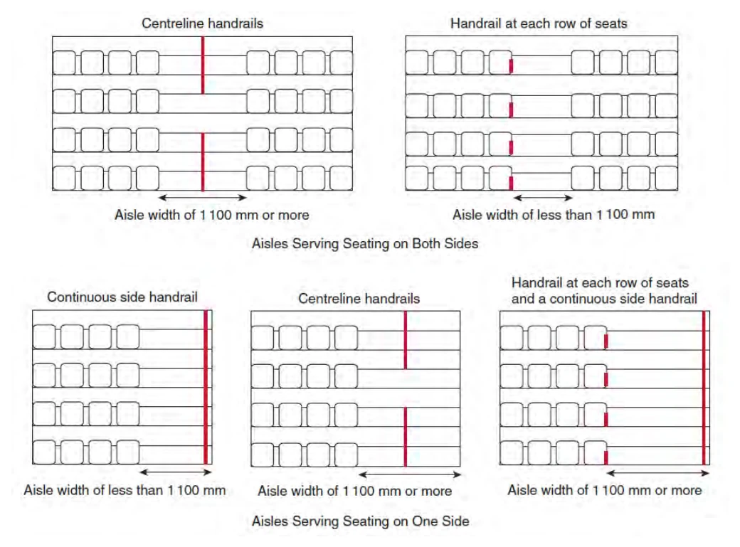
A-3.3.3.1.(1) Safety in a Care, Care and Treatment and Detention Occupancy. Copy linkAdd bookmark
Fire safety for patients and residents in sleeping room areas in care, care and treatment and detention occupancies is predicated on the ability of staff to carry out at all times essential life safety functions in accordance with the fire safety plan.
Many factors may affect the ability of staff to carry out life safety functions, including the mobility of patients who cannot fend for themselves and the built-in protection for patients who cannot be moved except under exceptional circumstances.
Should a patient area in a hospital or long-term care homes contain factors which would increase the time normally required for staff to evacuate patients or to undertake other life safety measures, consideration should be given to providing additional fire protection measures to ensure that equivalent safety is available.
A-3.3.3.4.(1) Doorway Width. Copy linkAdd bookmark
The 1 050 mm minimum clear width of doorways accounts for door stops and, thus, is intended to allow for the use of 1 100 mm doors.
A-3.3.3.5.(1) Hospitals and Long-Term Care Homes. Copy linkAdd bookmark
The basis for the requirements in this Article is that staff will be in attendance at all times on the same storey, either in each fire compartment or in a fire compartment immediately adjacent.
A long-term care home is intended to include skilled nursing facilities, intermediate care facilities and some homes for the aged. Occupants of long-term care homes are assumed to be, for the most part, non-ambulatory. The use of physical restraints and tranquilizing drugs which may render occupants immobile are also factors which should be considered.
Although the age of patients by itself is not sufficient justification for a floor area to be included in a long-term care home occupancy, it should be recognized that many homes for the aged are in fact long-term care homes. The factor that determines whether or not a home for the aged is a long-term care home and, therefore, a care and treatment occupancy, is whether or not continuous nursing care is required for the occupants. Where continuous nursing care and treatment is not provided for the occupants, a home for the aged may be classified as either a care occupancy or a residential occupancy. If no care is provided to the residents, a home for the aged would normally be classified as a residential occupancy.
A-3.3.3.5.(10) Intercommunicating Rooms. Copy linkAdd bookmark
Rooms that are interconnected can include more than one sleeping room, together with ensuite toilet rooms, shower rooms, and storage closets used for the storage of personal items of the persons occupying the sleeping rooms. It is not intended that storage rooms for other purposes be included within the group of interconnected rooms.
A-3.3.4.4.(1) Landing in Egress Stairway. Copy linkAdd bookmark
A landing level used in an egress stairway from a dwelling unit is not considered to be a storey of that dwelling unit if the landing is used only for pedestrian travel purposes.
A-3.3.4.5.(1) Automatic Locking Prohibited. Copy linkAdd bookmark
Doors that must be manually reset to lock them when they are opened from the inside meet the intent of this requirement.
A-3.3.4.9.(1) Stud Wall Reinforcement. Copy linkAdd bookmark
If the bathroom layout does not provide a wall beside the water closet, the reinforcing for future installation of a grab bar would only be required in the wall behind the water closet.
A-3.3.5.4. Electrical Wiring and Appliances. Copy linkAdd bookmark
Sources of ignition, such as electrical wiring and appliances, can set off an explosion if exposed to gases or vapours such as those that can be released in a repair or storage garage. The Ontario Electrical Safety Code contains provisions requiring either shielded wiring installations adjacent to certain garages or an air-tight curb separating the garage from adjacent spaces.
A-3.3.6.1.(1) Design of Hazardous Areas. Copy linkAdd bookmark
Subsection 3.3.6. applies to the storage of products, whether raw or waste materials, goods in process, or finished goods.
This Subsection does not deal with products or materials that are directly supplied to appliances, equipment or apparatus through piping, hose, ducts, etc. For example, gas cylinders that are mounted on propane barbeques are not covered by Subsection 3.3.6. since they are considered to be “in use” as opposed to “in storage”.
The design requirements contained in Subsection 3.3.6. reflect some, but not all design requirements contained in Division B of the Fire Code as it relates to the design of hazardous areas. Designers are advised to refer to the Fire Code for any other design requirements that may apply to their circumstances.
A-3.3.6.2.(2) Storage of Reactive Materials. Copy linkAdd bookmark
Reactive materials include various classes of unstable or reactive dangerous goods, such as flammable solids, pyrophoric materials, oxidizers, corrosives, water-reactive substances and organic peroxides.
In general, it is unsafe to store highly reactive oxidizers close to liquids with low flash points, combustible products or chemically incompatible products. Quantities of oxidizers or other dangerously reactive materials should therefore be limited and the storage area should be constructed of noncombustible materials, should be kept cool and ventilated, and should not impede egress.
In some cases, depending on the quantity and nature of the oxidizing agent, normal fire protection measures (e.g. sprinklers, fire hose and extinguishers) are ineffective due to the self-yielding of oxygen by the oxidizing agent.
When containers of highly reactive oxidizers become damaged or are exposed to excessive heat, humidity or contamination (e.g. sawdust, petroleum products, or other chemicals), a very violent fire or explosion can result.
The following oxidizing substances, among others, are known to supply oxygen: organic and inorganic peroxides; pool chemicals (e.g. calcium hypochlorite, sodium dichloroisocyanurate); oxides; permanganates; perrhenates; chlorates; perchlorates; persulfates; organic and inorganic nitrates; bromates; iodates; periodates; perselenates; chromates, dichromates; ozone; perborates.
When containers of dangerously reactive materials become damaged or are exposed to water or humidity, a flammable gas (such as hydrogen, ammonia or methane) or a toxic gas (such as hydrogen chloride, hydrogen bromide or phosphine) can be released.
The following dangerously reactive materials, among others, are known to release a flammable gas in reaction to contact with water or humidity: alkali metals (e.g. sodium, potassium, cesium); reactive metals (e.g. zinc, aluminum, magnesium); metallic hydride (e.g. sodium borohydride, germanium tetrahydride, calcium hydride).
The following dangerously reactive materials, among others, are known to release a toxic gas in reaction to contact with water or humidity: organic and inorganic chloride (e.g. phosphorus trichloride, phosphorus oxide trichloride, acetyl chloride); organic and inorganic bromide (e.g. phosphorus tribromide, aluminum tribromide, acetyl bromide).
A-3.3.6.4.(2) Explosion Venting in Hazardous Locations. Copy linkAdd bookmark
When a flammable mixture of air and vapour/gas/dust is ignited and causes an explosion, the exothermic reaction results in the rapid expansion of heated gases and the corresponding pressure waves travel through the mixture at sonic or supersonic velocities. The pressures developed by an explosion very rapidly reach levels that most building structures and equipment cannot withstand unless specifically designed to do so. Explosion venting consists of devices designed to open at a predetermined pressure to relieve internal pressure build-up inside a room or enclosure, hence limiting the structural and mechanical damage.
The major parameters to be considered in designing an explosion venting system for a building are:
- the physical and chemical properties of the flammable air mixture, such as the particle size or the droplet diameter, the moisture content, the minimum ignition temperature and the explosive concentration, the burning velocity or explosion classification, the maximum explosion pressure and the rate of pressure rise,
- the concentration and dispersion of the flammable mixture in the room,
- the turbulence and physical obstructions in the room,
- the size and shape of the room, the type of construction and its ability to withstand internal pressures, and
- the type, size and location of relief panels, which should be designed to reduce the possibility of injury to people in the immediate vicinity of the panels.
A-3.3.6.5.(1) Measurement of Tire Storage Volume. Copy linkAdd bookmark
The volume of tires in a storage area can be determined by measuring to the nearest 0.1 m the length, width, and height of the piles or racks intended to contain the tires. In racks, the top shelf is assumed to be loaded to a maximum possible height, while observing required clearances between structural elements and sprinklers.
A-3.3.6.6.(1) Products Stored with Ammonium Nitrate. Copy linkAdd bookmark
Copper and its alloys should not be used where they can come into contact with ammonium nitrate. The presence of copper represents the single greatest hazard with respect to the accidental detonation of ammonium nitrate during a fire.
Steel and wood can be protected with special coatings such as sodium silicate, epoxy, or polyvinyl chloride.
Asphalt and similar hydrocarbon-based roof coverings should not be used. Stored ammonium nitrate may become sensitized during a fire if such roof coverings melt and leak into the interior of the building, causing burning droplets to fall on the stored product.
A-3.4.1.6.(2) Sleeping Area. Copy linkAdd bookmark
Areas serving patients’ or residents’ sleeping rooms include sleeping areas and areas where patients or residents are taken for treatment.
A-3.4.2.3.(1) Least Distance Between Exits. Copy linkAdd bookmark
The least distance measurement does not apply to each combination of exits on a multi-exit storey. It only applies to at least 2 of the required exits from that storey.
A-3.4.3.2.(6) Evacuation of Interconnected Floor Space. Copy linkAdd bookmark
This Sentence ensures that egress facilities allow for the simultaneous evacuation of all portions of an interconnected floor space. It does not contemplate the phased evacuation of occupants; thus, in buildings where that type of evacuation is intended, fire protection requirements in addition to those prescribed in the Code may be necessary.
In the first instance, this Sentence provides for cumulative exiting that can accommodate the efficient movement of all occupants in the exit stairs. Clause 3.4.3.2.(6)(a) permits an alternative approach that will accommodate all the occupants in the stairs but will restrict the egress flow rate. Clause 3.4.3.2.(6)(b) provides a second alternative that assumes the occupants must queue before entering the stair. A “protected floor space” conforming to Article 3.2.8.5. is intended to provide an intermediate area of safety that is protected from the hazards of the interconnected floor space. It does not provide a holding or refuge area for all occupants of a floor area for an extended period of time.
To ensure that evacuation is not unduly delayed and that queuing of the occupants in the protected floor space can be accommodated, requires careful consideration in the design of the interface between the interconnected floor space/protected floor space/exit.
It is not appropriate, for example, to share a common vestibule in complying with Sentences 3.2.8.4.(1) and 3.2.8.5.(1). Under evacuation conditions, occupants entering the vestibule would flow towards the exit, as opposed to the protected floor space, thus resulting in queuing outside the vestibule and potential exposure to fire. To comply with the intent, it is necessary to design the egress path such that the occupants enter the protected floor space through a vestibule, then in turn enter the exit stair from the protected floor space. In addition, sufficient space should be provided between the vestibule and the exit to allow for the queuing of occupants in the protected floor space.
A-3.4.3.2.(6)(a) Temporary Safety Area. Copy linkAdd bookmark
The objective of Clause 3.4.3.2.(6)(a) is to provide an area of temporary safety in the exit stair shafts for the occupants of the interconnected floor space. This requirement is considered to be met if 0.3 m2 per person is provided in the stair shaft between the floor level served and the floor level immediately beneath it.
A-3.4.3.4. Clear Height and Width of Exits. Copy linkAdd bookmark
Clear height is intended to be measured from a line tangent to the nosings extended to the underside of the lowest element above the walking surface, over the clear width of the exit (see Figure A-3.4.3.4.) Examples of low elements above the walking surface include light fixtures, sprinkler heads and pipes.
Clear width is intended to be measured from a line tangent to the horizontal protrusions such as handrails.
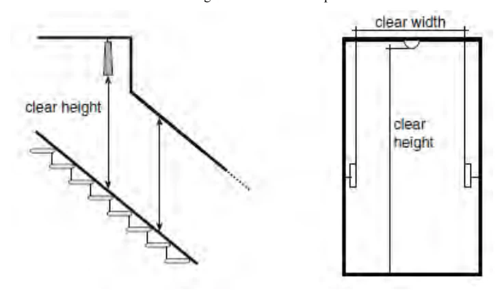
A-3.4.4.2.(2)(e) Requirements for Lobby. Copy linkAdd bookmark
If an exit is permitted to lead through a lobby, the lobby must provide a level of protection approaching that of the exit. As well as meeting the width and height requirements for exits, the lobby must be separated from the remainder of the building by a fire separation having a fire-resistance rating at least equal to that required for the exit, unless one of the exceptions in this Clause is applied.
A-3.4.5.1.(2)(c) Graphic Symbols for Exit Signs. Copy linkAdd bookmark
ISO 7010, “Graphic symbols - Safety colours and safety signs - Safety signs used in workplaces and public areas”, identifies the recognized symbols for use at required exits. Examples are provided in Figures 3.4.5.1.(2)(c)(i) and 3.4.5.1.(2)(c)(iii).


A-3.4.5.1.(4.1) Photoluminescent Exit Signs. Copy linkAdd bookmark
An external lighting source is required to properly charge photoluminescent signs. These types of signs must be lit in conformance with the charging requirements stated in CAN/ULC-S572, “Standard for Photoluminescent and Self-Luminous Exit Signs and Path Marking Systems”.
A-3.4.5.3.(2) Stairwell Signs. Copy linkAdd bookmark
Past experience indicates that some persons attempt to exit at the roof level of a building in the event of an emergency. Rescue from the roof of a building more than six storeys high is rarely possible from the exterior of a building. In order to avoid instances of persons getting trapped by smoke at the top of a stairwell that has no access to a roof, signs are required within the stairwell (at least one sign immediately above the highest normally occupied floor level) to indicate that the stairwell does not provide an exit at the roof level. The sign should consist of a graphic and text to indicate that there is no exit to the roof.
A-3.4.6. Application to Means of Egress. Copy linkAdd bookmark
The requirements in Subsection 3.4.6. apply to interior and exterior exits, as well as to ramps, stairways and passageways used by the public as access to exit. The treads, risers, landings, handrails and guards for the latter access to exit facilities must thus be provided in conformance with the appropriate requirements for exit facilities.
A-3.4.6.1.(1.1) Surface Finish of Ramps and Stairs. Copy linkAdd bookmark
A tactile attention indicator strip signals a warning to people with no or low vision that they are approaching a change in level. The strip is set back from the leading edge of the stair to provide sufficient warning of the change in level in advance.
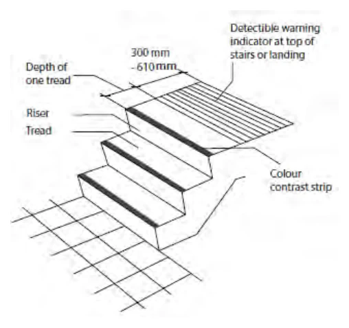
A-3.4.6.4. Dimensions of Landings. Copy linkAdd bookmark
A landing is a floor area provided at the top or bottom of a flight of stairs or a ramp, or a platform built as part of a stairway or ramp. Landings provide a safe surface for users to rest upon, allow design flexibility, and facilitate a change in direction.
Figure A-3.4.6.4. illustrates how to measure the length of a landing for various landing configurations turning less than 90 degrees, including straight landings.
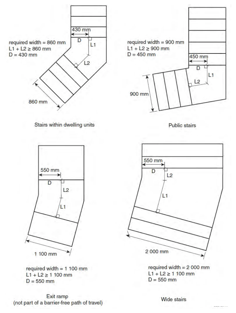
Notes to Figure A-3.4.6.4.:
A-3.4.6.5.(4) Wider Stairs than Required. Copy linkAdd bookmark
The intent of Sentence 3.4.6.5.(4) is that handrails be installed in relation to the required exit width only, regardless of the actual width of the stair and ramp. The required handrails are provided along the assumed natural path of travel to and from the building.
A-3.4.6.5.(10) Continuity of Handrails. Copy linkAdd bookmark
Persons with vision loss rely on handrails to guide them on stairways. A continuous handrail will assist them in negotiating stairs at changes in direction. The extended handrail is useful to persons with physical disabilities to steady themselves before using the stairs. Handrails should, however, return to the wall, floor or post, so as not to constitute a hazard to persons with vision loss.
A-3.4.6.5.(11) Termination of Handrails. Copy linkAdd bookmark
Handrails should terminate at the wall, floor or post so as not to constitute a hazard to persons.
A-3.4.6.8.(6) Stair Tolerances. Copy linkAdd bookmark
The term “shall not differ significantly” assumes normal construction tolerances.
A-3.4.6.10.(5) Door Swing. Copy linkAdd bookmark
Although it is required that the door on the right hand side of a pair of doors shall swing in the direction of travel through the exit, the direction of swing of the door on the left side will depend on the function of the horizontal exit. If the horizontal exit provides for movement from one building to the adjacent building but does not require movement in the reverse direction, both doors must swing in the direction of travel to the adjacent building. If the design is based upon both buildings providing complementary movement in either direction, then the doors must swing in opposite directions. Location of a required exit sign directly above a door that swings in the direction of travel is deemed to meet the intent of Clause 3.4.6.10.(5)(b).
A-3.4.6.11.(4) Exit Concealment. Copy linkAdd bookmark
Hangings or draperies placed over exit doors may conceal or obscure them.
Exit Doors Concealed with MuralsCopy linkAdd bookmark
Some people with cognitive disabilities such as dementia are at risk of wandering away from the residence or healthcare facility in which they are being treated. To reduce this risk, some residences and healthcare facilities install special hardware on egress and exit doors that can only be operated by designated persons. This solution keeps residents/patients from wandering, but the doors can still trigger anxiety in residents/patients who may nevertheless try to leave the space through them, without success.
Recent studies have shown that applying murals (of a landscape, for example) on exit and egress doors in these environments can help reduce anxiety in people with cognitive disabilities who tend to view them as a pleasant natural barrier rather than as a means of escape.
Where this approach is implemented and the doors are not reasonably discernible, an alternative means of egress from the space should be provided. It is expected that the designers and authorities having jurisdiction will use judgement in determining whether or not an alternative means of egress is required. Where this approach is implemented, the murals should be applied with care so that they do not conceal or impair the operation of any fire and life safety systems installed nearby, including, but not limited to, exit signage, emergency lighting, fire alarm devices, sprinklers or door hardware. Egress and exit doors with murals should be reasonably discernible to residential care or healthcare staff who will be required to assist residents/patients in the event that the space must be evacuated, and to visitors who will be expected to evacuate on their own.
A-3.4.6.16.(1) Fastening Device. Copy linkAdd bookmark
Turnpieces of a type which must be rotated through an angle of more than 90° before releasing a locking bolt are not considered to be readily openable. The release of a locking bolt should allow the door to open without having to operate other devices on the door.
A-3.4.6.16.(5) Electromagnetic Locks. Copy linkAdd bookmark
Electromagnetic locks are intended for use where there is a need for security additional to that provided by traditional exit hardware. They are not intended for indiscriminate use as alternative locking devices.
The design of these devices requires evaluation to ensure that their operation will be fail-safe in allowing exiting in the event of foreseeable emergencies.
If more than one locking device is used in a building, it is expected that one switch will release and reset all devices simultaneously. If more than one such switch is provided in a building, at least one switch must be installed in the annunciator panel located at the main entrance of the building or, in the case of a building within the scope of Subsection 3.2.6., in the central alarm and control facility for easy access of fire department personnel.
Most importantly, electromagnetic locks are not to be used where panic hardware must be installed. This will ensure that a large number of occupants can exit a building quickly in emergency situations created by either fire or non-fire conditions. It will also ensure that occupants in buildings containing highly hazardous substances can exit quickly unimpeded in an emergency.
In care and treatment facilities, such as hospitals and long-term care homes, and residential care facilities, however, because the occupant load is relatively low and the level of staff supervision is generally high, electromagnetic devices may be installed on exit doors at the bottom of exit stairways where panic hardware is required by code to maintain security where necessary.
When installed on doors in fire separations, electromagnetic locking devices must be used in conjunction with positive latching devices designed to hold the doors in the closed position since these locks do not incorporate latches and are released in an emergency. In a fire, keeping doors in fire separations closed is essential to control the spread of fire and smoke.
To enable exiting without delay (especially important in non-fire emergency situations), a manual station must be installed in close proximity to the door equipped with an electromagnetic locking device. The operation of this manual pull station will immediately release the electromagnetic locking device and, at the same time, activate the building fire alarm system.
Precautionary measures should be in place to ensure that by-pass switches would be deactivated at the completion of each fire alarm testing. An audible and a visual signal at the annunciator panel and at the monitory station should provide such assurance.
A-3.5.4.1.(1) Elevator Car Dimensions. Copy linkAdd bookmark
In some circumstances, it is necessary to maintain a patient on a stretcher in the prone position during transit to a hospital or to treatment facilities. Inclining the stretcher to load it into an elevator could be fatal or at the very least detrimental to the patient’s health. Many ambulance services use a 2 010 mm long by 610 mm wide mobile patient stretcher. As well as space for the stretcher in the elevator, there should be sufficient additional space for at least two attendants who may also be providing treatment during transit. Common elevator units that can satisfy this requirement include:
- a 1 134 kg elevator car with minimum interior dimensions of 2 032 mm wide and 1 295 mm deep with a right or left hand access door. The minimum access door width is 1 067 mm and it must be on the 2 032 mm side of the car.
- a 1 134 kg elevator car with minimum interior dimensions of 2 032 mm deep and 1 295 mm wide with a minimum 915 mm wide access door located on the 1 295 mm side.
A-3.6.2.1.(1) Location of Fuel-Fired Appliances. Copy linkAdd bookmark
Sentence 3.6.2.1.(1) requires that fuel-fired appliances be located in service rooms. It does not allow for their installation in service spaces.
A-3.6.2.5.(1) Storage of Combustible Refuse and Recycling. Copy linkAdd bookmark
Storage of refuse consisting of combustible materials including waste paper, cardboard and plastic, and noncombustible materials such as glass and metallic containers can be accumulated in these rooms for the purpose of recycling. The storage of hazardous materials destined for recycling may need to satisfy other requirements than those stated in Sentence 3.6.2.5.(1).
A-3.6.2.7.(8) Vertical Service Spaces. Copy linkAdd bookmark
Examples of good engineering practice for this application can be found in NFPA 68, “Standard on Explosion Protection by Deflagration Venting,” NFPA 69, “Standard on Explosion Prevention Systems,” and the NFPA “Fire Protection Handbook.”
A-3.6.3.1.(1) Vertical Service Spaces. Copy linkAdd bookmark
Sentence 3.6.3.1.(1) does not prohibit the internal subdivision of a vertical service space to allow different building services to be installed in physically separated spaces unless other requirements apply (see, for example, Article 3.2.7.10.). Fire separation requirements apply to the perimeter of the group of service spaces. Article 3.6.3.3. has special requirements for linen chutes and refuse chutes.
A-3.6.3.5. Grease Duct Enclosures. Copy linkAdd bookmark
NFPA 96, “Ventilation Control and Fire Protection of Commercial Cooking Operations”, presents two options for enclosing grease ducts for commercial cooking equipment: the first option is to use continuous fire-rated building component assemblies to enclose the ducts and the second one consists of installing proprietary, fire-rated, field- applied or factory-built grease duct assemblies in accordance with the manufacturer's instructions. These types of enclosure assemblies are evaluated for their resistance to fire and their ability to protect adjacent combustibles through reduced clearances. Although NFPA 96 references other standards that deal with grease duct assemblies, Sentence 3.6.3.5.(2) requires that CAN/ULC-S144, “Standard Method of Fire Resistance Test – Grease Duct Assemblies”, be used to determine the fire-resistance rating of factory-built and field-applied grease duct assemblies.
A-3.6.4.2.(2) Ceiling Membrane Rating. Copy linkAdd bookmark
In construction assemblies that utilize membrane ceiling protection and have been assigned a fire-resistance rating on the basis of a fire test, the membrane is only one of the elements that contribute to the performance of the assembly and does not in itself provide the protection implied by the rating. For the fire-resistance rating of membrane materials used in this form of construction, reference should be made to the results of fire tests which have been conducted to specifically evaluate the performance of this element.
A-3.6.5.6.(2) Clearance for Warm-Air Supply Ducts. Copy linkAdd bookmark
Applicable to forced-air furnaces where permissible clearance C above plenum is 75 mm or less.
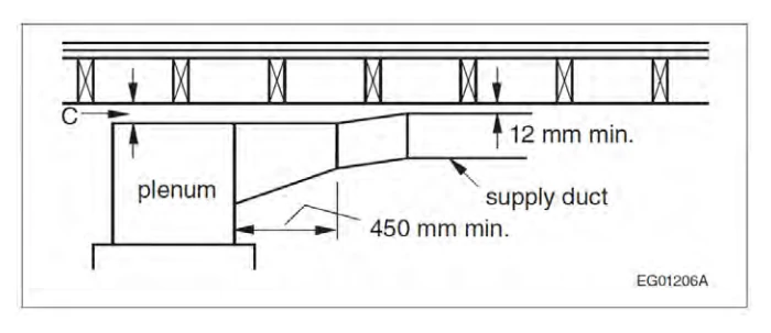
A-3.6.5.6.(3) Clearance for Warm-Air Supply Ducts. Copy linkAdd bookmark
Applicable to forced-air furnaces where permissible clearance C above plenum is more than 75 mm but not more than 150 mm.
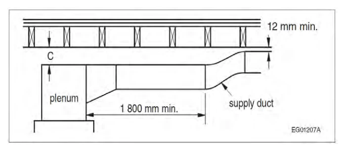
A-3.6.5.6.(4) Clearance for Warm-Air Supply Ducts. Copy linkAdd bookmark
Applicable to forced-air furnaces where permissible clearance C above plenum is more than 150 mm.
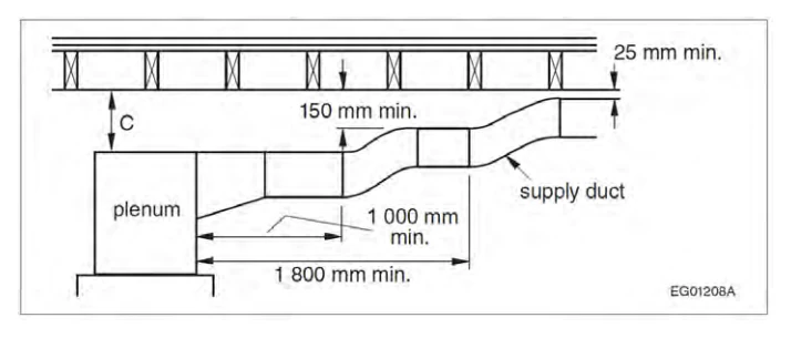
A-3.7.2.1.(1) Window Area Limit. Copy linkAdd bookmark
Part 9 requirements for windows cover a number of subjects, however, this Article refers only to the area limits.
A-3.7.4.2.(1) Sanitary Facilities. Copy linkAdd bookmark
It is assumed that if the sanitary facilities are provided on every storey, the occupant load for the determination of the number of fixtures would be the anticipated occupant load of that storey. If the washrooms are provided in a central location, the number of fixtures should then be based on the total anticipated occupant load for the areas that are served by that washroom.
A-3.7.4.2.(2) Washroom Units in Industrial Occupancies. Copy linkAdd bookmark
Substations and parking garages are examples of industrial occupancies where staff presence may be permanent or may be intermittent. In the case of parking garages, the presence of occupants other than staff is transitory.
A-3.7.4.2.(3) Sanitary Facilities. Copy linkAdd bookmark
Although traditional industry practice has provided separate gender identified washrooms, there is no implied or specific requirement in the code that requires this. As such, washrooms do not need to be separated into distinct gender-specific rooms. The Code’s provisions require a design that includes an adequate total number of water closets and urinals be provided for the number and demographics of building occupants. For gender neutral washrooms, features such as full height partition walls for the privacy of washroom users, and doors with locks for safety should be considered in the space’s design. Where washrooms are required to be accessible, Section 3.8. will apply.
A-3.7.4.2.(6) Lavatories. Copy linkAdd bookmark
This provision is intended to ensure that a sufficient number of lavatories are provided based on the number of water closets or urinal, in order to maintain personal hygiene.
A-3.7.4.2.(9) Plumbing Fixtures for Small, Low Occupancy Uses. Copy linkAdd bookmark
For small restaurants, retail and other small assembly uses with low occupancy loads, the number of washrooms provided may be reduced, where permitted, to provide some flexibility for space planning provided at least one universal washroom is provided in compliance with Sentence 3.8.3.12.(6) and one single washroom is provided and neither washroom is signed for gender.
A-3.7.4.12.(1) Washrooms for Public Use. Copy linkAdd bookmark
The definition of public use clarifies that facilities for public use must have unrestricted access. Since a washroom in a hotel room is restricted for the use of the hotel guest only, it is an example of a washroom that would be exempt from requiring a floor drain. Also, the definition of private use includes a washroom in a hotel suite.
A-3.7.4.14.(1) Clearances for Water Closets. Copy linkAdd bookmark
The minimum clearance in front of a water closet is intended to be measured from the front edge of the seat to:
- the nearest point of the wall or cubicle enclosure,
- another fixture, or
- the washroom door or stall door when the door is in the closed position.
A-3.7.5.3.(1) Shielding of X-Ray Equipment. Copy linkAdd bookmark
Every installation of an x-ray machine or x-ray equipment used for the exposure of persons shall be shielded with a primary and a secondary protective barrier to protect any person who could be exposed to radiation. This protection is required for
- x-ray workers
- persons other than patients undergoing an application of therapeutic or diagnostic x-rays
- persons in adjacent buildings
- persons located outdoors of buildings containing x-ray equipment.
These protective barriers should be designed and installed to comply with requirements of The Healing Arts Radiation Protection Act. Applications for approval for these installations should be addressed to the Ministry of Health and Long-Term Care.
Similarly, every installation of an x-ray machine or x-ray equipment for industrial or veterinary applications shall be shielded with a primary and a secondary protective barrier to protect any person who could be exposed to radiation. This protection is required for
- x-ray workers,
- persons other than x-ray workers,
- persons in adjacent buildings, and
- persons located outdoors of buildings containing x-ray equipment.
The protective barriers should be designed and installed to comply with requirements of The Occupational Health and Safety Act. Applications for approval for these installations should be addressed to the Ministry of Health and Long-Term Care.
A-3.8. Barrier-Free Design Assumptions. Copy linkAdd bookmark
This Section contains minimum provisions to accommodate a person using a typical manual wheelchair or other manual mobility assistance devices such as walking aids, including canes, crutches, braces and artificial limbs. The Code also includes provisions to address needs of people with sensory disabilities.
All dimensions to objects such as controls, switches and grab bars provided in Section 3.8. are considered to be measured to the centre line of such objects unless otherwise specified in Section 3.8.
A-3.8.1.1.(1)(b) Industrial Occupancies. Copy linkAdd bookmark
Industrial buildings often pose a greater risk to their occupants due to the presence of significant quantities of dangerous materials or the use of hazardous processes. For example, plants which are classified as Group F, Division 2 or 3, may store and use toxic or highly flammable substances in significant quantities, or house processes which involve very high temperatures and which may have a high degree of automation. In some facilities, particularly in primary industries such as forestry and metallurgy, the construction normally used and the operations carried out within the space can make compliance with the requirements of Section 3.8. impractical. It is therefore intended that these requirements be applied with discretion in buildings of Group F, Division 2 or 3 major occupancy. However, where industrial buildings contain subsidiary occupancies, such as offices or showrooms, it is reasonable to require that accessibility be provided in these spaces.
A-3.8.1.1.(1)(d) Camps for Temporary and Emergency Workers. Copy linkAdd bookmark
The exemption of camps for housing of workers from barrier-free design requirements is intended to exempt accommodations for seasonal workers such as agricultural workers or emergency workers such as firefighters working in remote areas.
A-3.8.1.2. Barrier-Free Entrances. Copy linkAdd bookmark
A barrier-free path of travel should be provided from the sidewalk or roadway and parking areas to a barrier-free building entrance. This route should be located so that persons with disabilities do not have to pass behind parked cars. The number of barrier-free entrances to a building must be not less than the minimum number required in Table 3.8.1.2. in order to provide more general and equitable access to the building and should include the principal entrance. For the purpose of determining the number of entrances to a building, several adjacent doors in a bank of doors are considered to be a single entrance. The principal entrance to the building is the entrance that is normally used by the public or the building occupants.
A-3.8.1.3.(2) Surfaces in a Barrier-Free Path of Travel. Copy linkAdd bookmark
Floor finishes, including walk-off matts and carpet, should be selected, installed and securely fixed to provide a firm and stable surface so that persons using wheelchairs, walkers or other mobility aids can easily travel over them without tripping or expending undue energy. Other than very high-density, short-pile carpeting, most carpeting does not meet these criteria.
Furthermore, where the path of travel is exposed to intense light conditions, such as daylight or directional lighting, a low-glare or matte floor surface should be selected as glare from floor surfaces can bother all users and be particularly problematic for individuals with a vision impairment. For the same reasons, heavily patterned flooring should also be avoided.
A-3.8.1.3.(4) Unobstructed Space. Copy linkAdd bookmark
The 1800 mm by 1800 mm space spaced every 30 m provides a layby area where two wheelchairs can pass.
A-3.8.1.3.(5) and (6)(b) Reduced Headroom. Copy linkAdd bookmark
Wherever an overhead obstruction occurs within or adjacent to a barrier-free path of travel such as the underside of a stairway or escalator or a building structural element, a cane-detectable barrier will provide an effective warning to people with no or low vision that headroom is reduced and the path is obstructed to prevent them from moving toward the obstruction.
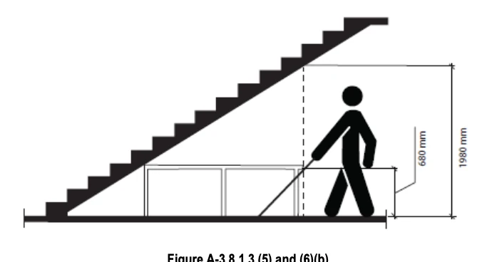
A-3.8.1.4.(1) Access to Storeys Served by Escalators and Moving Walks. Copy linkAdd bookmark
In some buildings, escalators and inclined moving walks are installed to provide transportation from one floor level to another floor level so as to increase the capacity to move large numbers of persons. Some buildings located on a sloping site are accessible from street level on more than one storey and an escalator or inclined moving walk is provided for internal movement from floor to floor. In both these situations, a person with a physical disability must be provided with an equally convenient means of moving between the same floor levels within the building. A wheelchair user should not be required to travel outside the building in order to gain access to another level. This can be accomplished by providing an elevator or a platform-equipped passenger-elevating device.
A-3.8.1.5.(1) Controls. Copy linkAdd bookmark
Building controls that are intended to be operated by the occupants include thermostats, light switches, intercoms and other controls for building use and comfort. It is not intended to include those controls that are secured for use by building operations, maintenance and management personnel.
Light switches, intercoms and similar devices located within a barrier-free path of travel should be located between 900 mm and 1100 mm above the finished floor. Thermostats should be mounted at 1200 mm on centre above the finished floor for the optimal operation.
A-3.8.2.1.(1) Access to Rooms and Facilities. Copy linkAdd bookmark
If barrier-free access is required into suites or rooms in Subsection 3.8.2., it is intended that access be provided, with some exceptions identified in Sentence 3.8.2.1.(2), throughout each room or suite. Some examples of where barrier-free access is required are as follows:
- within rooms or areas that serve the public or are designated for use by visitors, including areas in assembly occupancies with fixed seats, display areas and merchandising departments,
- within rooms or areas for student use in assembly occupancies,
- within general work areas, including office areas,
- within general use or general service areas, including shared laundry areas in residential occupancies, recreational areas, cafeterias, lounge rooms, lunch rooms and infirmaries,
- within sleeping rooms in hospitals and long term care homes,
- (if installed), into at least one passenger elevator or elevating device conforming to Article 3.8.3.5.,
- into washrooms described in Article 3.8.2.3.,
- to any facility required by this Section to be designed to accommodate persons with physical disabilities,
- onto every balcony provided in conformance with Sentence 3.3.1.7.(2),
- to service counters used by the general public (examples include ticket counters, refreshment stands, drinking fountains, cafeteria counters, checkout counters and bank service counters)
- into 10% of hotel suites, (not more than 20 suites required), and
- within 15% of residential suites in an apartment building from the suite entrance door into at least one bedroom and bathroom at the same level as the suite entrance.
A-3.8.2.1.(1)(b) Rooftop Amenity Spaces. Copy linkAdd bookmark
External rooftop areas of buildings that are designed for use as amenity spaces for building occupants must be made accessible to people with disabilities. This includes rooftop terraces, patios and barbecue facilities and requires that a barrier-free path of travel be provided from the floor area to the rooftop amenity space. Exterior roof spaces that are only accessed for the purpose of building and equipment maintenance and operations are not required to be barrier-free accessible and will continue to be exempt from barrier-free design requirements under Clause 3.8.2.1.(3)(f).
A-3.8.2.1.(2) Portions of Floor Areas not Required to be Barrier-Free. Copy linkAdd bookmark
The permission to waive a barrier-free path of travel for wheelchair access to certain specified areas of a building is not intended to waive accessibility requirements for persons with physical disabilities who do not require special provision for access to raised or sunken levels. Persons with visual or hearing disabilities that do not require the use of a wheelchair can be expected to move throughout a building.
The concept of wheelchair accessibility does not extend to building service facilities, nor to all floor levels within a storey, e.g., mezzanines not served by an elevator. Mezzanines that are accessible by an elevator are therefore not excluded.
Seating booths and banquettes in restaurants and bars are considered furniture, which is beyond the scope of the Code. However, various types of seating should be considered to ensure the availability of barrier-free options.
Accessibility “within” a floor area is intended to mean that in general all normally occupied spaces are to be accessible, except where essential obstructions in the work area would make a barrier-free path of travel hazardous. Examples of excluded floor areas could include small raised office areas in retail and industrial premises, storage platforms in industrial occupancies, repair garages and areas within commercial kitchens.
Where a floor area does not require a barrier-free path of travel, certain barrier-free design provisions of Section 3.8. will still be applicable. These requirements can provide greater accessibility for persons with limited mobility who do not use wheelchairs or for those with sensory disabilities. People using walking aids, service animals or those with hearing and vision loss may still be able to climb stairs or use escalators. Accessibility features such as wider door openings, lever door handles and larger washroom stalls can also assist other building users.
The applicable requirements include: 3.8.1.3.(6) – Headroom and walking surfaces 3.8.2.3.(6) – Non-barrier-free washrooms 3.8.3.1.(6) – Accessibility signs 3.8.3.3.(19) – Doors, door hardware and vision panels 3.8.3.8.(10) – Ambulatory water closet stalls 3.8.3.10.(5) – Urinals 3.8.3.11.(5) – Lavatories 3.8.3.15.(5) – Counters for telephones 3.8.3.16.(4) – Drinking fountains
A-3.8.2.1.(2)(b) Exemptions from Barrier-Free Path of Travel for Small Buildings. Copy linkAdd bookmark
Some small buildings are restricted in building area by lot size, including small infill properties between existing buildings. In those cases, it may not be feasible to require an elevator for the building. This Clause does not exempt areas requiring barrier-free path of travel described in Clause 3.8.2.1.(1)(a) and Sentence 3.8.2.1.(5), from being met.
A-3.8.2.1.(3) Exemptions for Service Facilities. Copy linkAdd bookmark
The concept of wheelchair accessibility does not extend to building service facilities. Nor does it extend to all floor levels within a storey, e.g., mezzanines not served by an elevator. Mezzanines that are accessible by an elevator are not excluded.
A-3.8.2.1.(3)(m) Access to Facilities on a Floor Level Other than the Entrance Level Copy linkAdd bookmark
Subclauses 3.8.2.1.(3)(m)(ii) to (iv) are intended to exempt certain storeys other than the entrance level - including basements and mezzanines that are less than 600 m2 in floor area or 100 m2 or less in floor area in assembly occupancies, that are self-contained, or that contain the same facilities as the entrance level - from the requirement to have a barrier-free path of travel.
Examples of buildings and spaces to which this exemption may apply are small office buildings with additional workspaces on the second storey and small restaurants with a second storey that contains only additional seating. However, if a restaurant's only washrooms are in the basement, they must have a barrier-free path of travel as they are an integral part of the principal function of the first storey. Similarly, staff lunchrooms and washrooms are also integral to the principal function of a restaurant; as such, if they are located in a floor area such as a second storey, basement or mezzanine that contains essential facilities as described in Subclause 3.8.2.1.(3)(m)(iii), they must have a barrier-free path of travel for potential employees with disabilities.
Where a building contains more than one floor level, other than the entrance level, each floor level should be considered individually when determining the floor area for the purposes of Subclauses 3.8.2.1.(3)(m)(ii) and (iv). Mezzanines should be considered as a floor level other than the entrance level.
A-3.8.2.1.(4) Designated Wheelchair Spaces and Adaptable Seating. Copy linkAdd bookmark
Spaces designated for wheelchair use, and for adaptable seating, should be distributed in various locations throughout the venue in order to provide a choice of seating location for patrons. Seating spaces should be located adjacent to a barrier-free access aisle or an open space to facilitate ease of manoeuvring a wheelchair into position or to facilitate a side transfer to a fixed adaptable seat. Figure A-3.8.2.1.(4) provides an example of distribution of adaptable seats, designated wheelchair spaces, and mobility aid storage spaces in an auditorium.
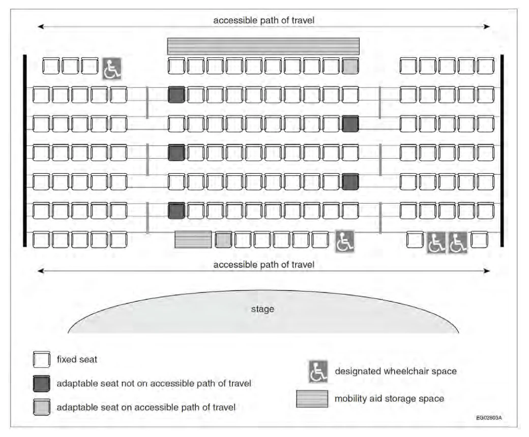
A-3.8.2.1.(5) Number of Apartments Required to be Barrier-Free. Copy linkAdd bookmark
The intent behind Sentence 3.8.2.1.(5) is that, in calculating the 15% of apartments in a multi-unit apartment building required to be barrier-free, the 15% of units is determined based on whole numbers as indicated in the examples set out in Table A-3.8.2.1.(5) and not based on fractions of units.
| Number of Apartments | Minimum Number of Barrier-Free Apartments |
|---|---|
| 1 to 6 | 1 |
| 7 to 13 | 2 |
| 14 to 19 | 3 |
| 20 to 26 | 4 |
| 27 to 33 | 5 |
| 34 to 39 | 6 |
A-3.8.2.1.(5)(a) and (b) Access to Bedrooms and Bathrooms in Apartments. Copy linkAdd bookmark
This requirement ensures that a person using a wheelchair can enter a bedroom and a bathroom within 15% of apartment suites and 10% of hotel and motel suites. A barrier-free path of travel and clearances on the latch side of the doors to the designated bedroom and bathroom must be provided.
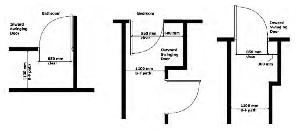
A-3.8.2.1.(6) Residential Bathrooms. Copy linkAdd bookmark
The intent of the barrier-free features required in 15% of apartment bathrooms, is to provide basic manoeuvrability into, and within, the space for a wheelchair user. The door swing may overlap the turning circle within the bathroom as long as there is sufficient space for a wheelchair user to clear the door and close the door. The bathroom is not required to include a barrier-free bathtub or barrier-free shower meeting the requirements of Article 3.8.3.13. The intent is not to provide accessibility for a full range of disabilities which may require additional features to accommodate the specific needs of an individual resident. However, stud wall reinforcement for the future installation of grab bars is required in the main bathroom in all dwellings as set out in Articles 9.5.2.3. and 3.3.4.9.
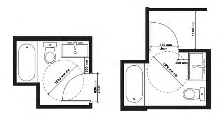
A-3.8.2.1.(7) Distribution of Apartments with Accessible Features. Copy linkAdd bookmark
The intent is to provide a variety of suite sizes and locations and not locate all suites with barrier-free design features on the same floor. The intention is to provide a level of visitability to apartments. Given the broad range of disabilities and the specific needs of people with disabilities in their home settings, the accessibility provisions may not provide all of the features required by an individual’s personal needs that cannot be anticipated when the building is constructed initially.
The intent behind Sentence 3.8.2.1.(7) is that, in determining the proportion of barrier-free suites by unit size, the total number of barrier-free suites and the percentage of suites of each type (by number of bedrooms) should be calculated first. Those percentages should be multiplied by the total number of barrier-free suites required. For example, in a 40 unit apartment building with 30 one-bedroom and 10 two-bedroom units, 6 suites in total would be required to be barrier-free. The proportional breakdown of required barrier-free suites would be 75% or 5 one-bedroom suites and 25% or one two-bedroom suite. The proportion of units is also determined based on whole numbers and not based on fractions of units as long as the total number of barrier-free suites are provided.
Studio or bachelor apartments are a specific type suite and are intended to be counted separately when determining the proportion of suites, by type and size, in a building. Where studio or bachelor suites are provided, a proportionate number of studio or bachelor suites should also be accessible even though those suite types do not include a separate bedroom. For example, if 25% of the units in a building are studios, 50% are one-bedroom units and 25% are two-bedroom units, the same proportions should be reflected in the 15% of total units required to include barrier-free design features. The Building Code does not differentiate one- or two-bedroom units from one- or two-bedroom units with dens. The intent is that a range of unit types and sizes are available as accessible units.
A-3.8.2.2. Parking Areas. Copy linkAdd bookmark
In localities where local regulations or bylaws do not govern the provision of or dimensions of barrier-free parking spaces, the following provides guidance to determine appropriate provisions. If more than 50 parking spaces are provided, parking spaces for use by persons with physical disabilities should be provided in the ratio of one for every 100 parking spaces or part thereof. Parking spaces for use by persons with physical disabilities should
- (1) be not less than 2 400 mm wide and provided on one side with an access aisle not less than 1 500 mm wide,
- (2) have a firm, slip-resistant and level surface,
- (3) be located close to an entrance required to conform to Article 3.8.1.2.,
- (4) be clearly marked as being for the use of persons with physical disabilities, and
- (5) be identified by a sign located not less than 1 500 mm above ground level, with the International Symbol of Access and the words “Permit Required” (Figure A-3.8.2.2.-A).
Asphalt, concrete and gravel are acceptable parking surfaces. Curb ramps should be not less than 920 mm wide. Parallel parking spaces should be not less than 7 000 mm long. If more than one parking space is provided for persons with physical disabilities, a single access aisle can serve two adjacent parking spaces. The arrangement shown in Figure A-3.8.2.2.-B allows the shared use of an access aisle to serve two adjacent parking spaces provided for use by persons with physical disabilities.
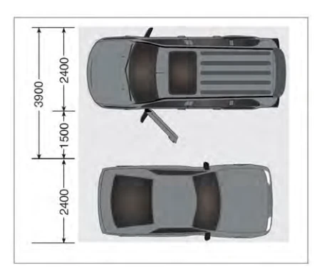
A-3.8.2.2.(1) and (4) Barrier-Free Paths of Travel to Building Entrances, Exterior Passenger Loading Zones and Access to Parking Areas. Copy linkAdd bookmark
The intent of Sentences 3.8.2.2.(1) and (4) is to ensure that exterior barrier-free paths of travel are readily available so that persons of all abilities can move to and from a building with minimal effort and in a manner that minimizes the total distance required to be travelled.
A-3.8.2.3. Washrooms. Copy linkAdd bookmark
The primary intent of this requirement is that all regular washrooms be made accessible to all persons, including persons with disabilities, primarily persons who must use a wheelchair.
The exception in Clause (5)(b) recognizes situations where several washrooms may be provided on a large floor area. In such a case, not all washrooms need to be barrier-free, provided that a barrier-free washroom is available within a reasonable distance (45 m) of one that is not barrier-free and that the location of that barrier-free washroom is clearly indicated as required by Sentence 3.8.3.1.(3).
Clause 3.8.2.3.(5)(c) is intended to address “strip malls” (a shopping mall with no public corridor). Section 3.7. which requires plumbing facilities, does not address the concept of suite and could permit, for instance, a shopping mall containing only Group E occupancies (assuming the mall is more than 100 m2) to have only one washroom for each sex located in any one of the suites. It is desirable however that such washrooms be located so as to be accessible at all times, since the owner or tenant of one suite has no control over the activities of another. Such buildings may either provide public barrier-free washrooms in a central location or washrooms which can accommodate disabled persons in each suite. This arrangement relieves any one tenant from having to provide “public” washrooms. Hence, the exception for suites of less than 300 m2 is meant as a relaxation to avoid an unnecessary burden on small facilities but should not be construed as meaning that such buildings need not provide accessible washrooms.
A-3.8.2.3.(2) Minimum Number of Universal Washrooms. Copy linkAdd bookmark
The requirements for the number of universal washrooms in buildings are set out in Article 3.8.2.3. and Table 3.8.2.3.A. Sentence 3.8.2.3.(2) refers back to Subsection 3.7.4. which sets out the number of washrooms required in buildings by occupancy.
The intent of the new requirements in Table 3.8.2.3.A is to provide additional universal washrooms in uses and occupancies where washrooms are required and not to require washrooms where they had not been required previously. For that reason the requirements are linked back to Subsection 3.7.4. For example, in the case of a high-rise apartment building, floors with only apartment units and without any common amenity spaces, would not require a universal washroom, nor would 3 levels of underground parking below the building.
Using the ratio of ‘1 universal washroom for every 3 storeys’ is a way to determine the number of universal washrooms in a building but without specifying where they should be located. The intent of the Code is to provide designers and building owners flexibility to locate the washrooms as appropriate to the building design and operation. For example, a six storey office building would require 2 universal washrooms (1 per 3 storeys) but those could both be on the same storey or on different storeys – not necessarily on the first and fourth floors or on every third storey.
A-3.8.2.3.(3) Minimum Number of Barrier-Free Water Closet Stalls. Copy linkAdd bookmark
Washrooms that contain barrier-free washroom stalls and barrier-free lavatories, typically meet the needs of single users with disabilities. The requirements for universal washrooms, in addition to barrier-free washrooms, accommodate people with disabilities who require assistance from a same or opposite gender care giver.
A-3.8.2.3.(5)(b) Individual Washrooms. Copy linkAdd bookmark
Washrooms, in excess of those required under Subsection 3.7.4., that are provided for private or individual use within an individual suite where washrooms for public use are provided elsewhere in the building, are not required to meet barrier-free design requirements. This could include a single user washroom that is part of a private office or a small retail store.
A-3.8.2.3.(6) Ambulatory Water Closet Stalls. Copy linkAdd bookmark
Washrooms on storeys that are not required to have a barrier-free path of travel are still required to provide a washroom stall in each washroom that includes certain barrier-free design elements in order to accommodate people with disabilities who are ambulatory but still need some supports.
A-3.8.2.4.(1) Number of Hotel Rooms Required to be Barrier-Free. Copy linkAdd bookmark
The intent behind Sentence 3.8.2.4.(1) is that, in calculating the 10% of hotel rooms required to be barrier-free, the 10% of units is determined based on whole numbers and not based on fractions of units. A small hotel with 9 suites or fewer, would not require any barrier-free rooms.
A-3.8.2.4.(7) Emergency Power Outlet. Copy linkAdd bookmark
An outlet on emergency power is required to provide power for a guest with a disability who needs constant support from equipment such as a ventilator or oxygen concentrator generator.
The emergency power receptacle need only be provided in one of the suites required to have accessible features. This outlet must be identified and signed as being on emergency power.
A-3.8.3.1. Accessibility Signs. Copy linkAdd bookmark
The International Symbol of Access, as shown in Figure 3.8.3.1.-A below, indicates to persons with disabilities that they will have reasonable freedom of movement within the building. It usually has a blue background, but if, because of lighting conditions, it may not stand out, it can be set on a white background. An arrow can be added to either side or to the top or bottom to indicate direction or the location of an accessible space or facility.
An International Symbol of Access for Hearing Loss, shown in Figure A-3.8.3.1.-B, indicating accessibility for persons with hearing loss, should be used to indicate the availability of variable volume controls on telephones, assistive listening systems, and text telephones (TT). These latter devices may also be referred to as teletypewriters (TTY) or telecommunications devices for the deaf (TTD).
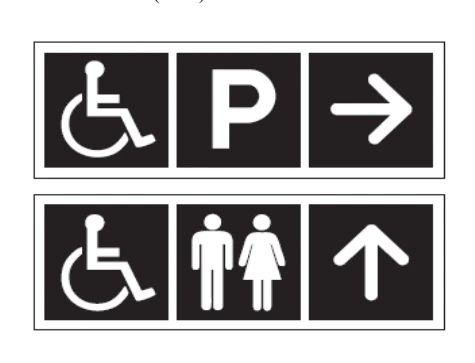

A-3.8.3.1.(7) and (8) Visual and Tactile Information Signs. Copy linkAdd bookmark
This requirement only applies to those signs which are required under the Building Code including those for washrooms, directional signs to building entrances and parking areas.
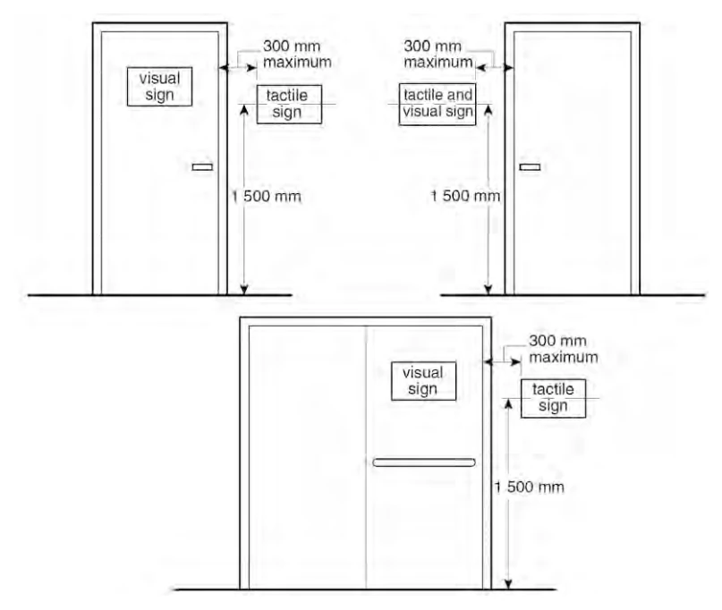
A-3.8.3.2.(1)(h) Tactile Indicators at Exterior Walks. Copy linkAdd bookmark
The requirement for a tactile indicator surface installed at specified locations is to provide a tactile signal that an individual is moving toward a potential hazard such as a curb cut at a vehicular route or the edge of a level rapid transit platform.
A-3.8.3.3.(1) Doorway Width. Copy linkAdd bookmark
Standard wheelchair width specifications indicate a range of sizes from 584 mm overall to 685 mm overall. Every doorway that is located in a barrier-free path of travel must have a clear width of not less than 850 mm when the door is in the open position and therefore it is important that this dimension be measured correctly.
Figure A-3.8.3.3.(1) shows a door opened to 90°. It is clear that the door, and to a lesser extent the stop, impinges on the space within the door frame. The clear width of not less than 850 mm is measured from the face of the door to the outside edge of the stop on the door frame. It is not sufficient just to measure the inside width of the door frame or the width of the door panel. There should be no projections into the required clear opening width lower than 865 mm above the finish floor or ground. Projections into the clear opening width between 865 mm and 2030 mm above the finish floor or ground should not exceed 100 mm.
Other factors, including location of door stops other than on the door frame, and the installation of door closers and exit devices, should be taken into account. The intrusion of a door handle into the space is of lesser importance. It is recognized that there are many types of door frame and door mounts, but the overall objective is to maintain a clear width of not less than 850 mm. The diagram depicts a somewhat restrictive scenario, as many doors can open wider than 90° to ensure the minimum clear width of 850 mm that is required.
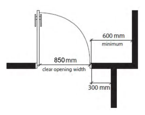
A-3.8.3.3.(2) Washrooms and Bedrooms in Residential Occupancies. Copy linkAdd bookmark
This requirement ensures that the width of a doorway to the washroom and the bedrooms in relation to the corridor width leading to those rooms in a dwelling unit or a hotel/motel suite can provide for basic maneuverability into and out of the room. The Code does not require these washrooms (except the 15% required by Sentence 3.8.2.1.(5) and 10% required by Article 3.8.2.4.) to be barrier-free.
A-3.8.3.3.(3) Accessible Door Handles. Copy linkAdd bookmark
Door handles that can be operated with a closed fist include lever-style handles which are useable by most persons with limited hand mobility and will meet the intent of this requirement. Lever handles with an end return towards the door are less prone to catch the clothing of someone passing through the doorway. Where the door is a sliding door with manual controls, it shall be configured so that the hardware is exposed and usable from both sides when the sliding door is in the open position.
A-3.8.3.3.(4) Doors with Power Operators. Copy linkAdd bookmark
Doors equipped with a power operator activated by a pressure plate identified with the international symbol of access or, where security is required, by a key, card or remote device, and that can otherwise be opened manually meet the intent of the requirement. The device selected should consider ease of use by people with disabilities including those with limited hand motion and dexterity. The location of these activating devices should ensure that a wheelchair will not interfere with the operation of the door once it is activated. Where the power door operator is provided for one leaf of a pair of double, out-swinging doors, the door operator should be located so that it is as close as possible to the latch side or, beyond the door swing so that the door does not obstruct the path of travel.
Swinging doors equipped with power operators which are activated automatically and open into passing pedestrian traffic should be provided with a guard or other device designed to prevent pedestrians from stepping in the swing area of the door. These guards or devices should be detectable by blind persons. For example, inverted U-shaped guards should have an additional rail at a height not more than 680 mm so that it is detectable by the long cane. These doors should also have a device (mat or other sensor) on the swing side to prevent the door from opening if someone is standing in the swing area.
A-3.8.3.3.(4.1) Power Door Operators for Interior Doors. Copy linkAdd bookmark
This requirement is not intended that all doors located in a barrier-free path of travel be equipped with a power door operator, but rather those, that are located within public areas of the building, such as public corridors or corridors used by the public. Doors of suites served by a public area do not need to be equipped with a power door operator.
A-3.8.3.3.(8) Air Pressure Differences. Copy linkAdd bookmark
Differences in air pressure on opposite sides of a door may be due to the operation of mechanical systems such as those associated with smoke control. So-called “stack action” in buildings in winter can also cause differential pressures due to the buoyancy of warm air. Stack action is usually most noticeable between stairwells and the remainder of the building, and at the entrances to buildings; the taller the building, the greater the effect. Doors with automatic closers have to operate with sufficient opening forces to allow the return action to overcome the differential pressure.
A-3.8.3.3.(9) Delayed Action on Door Closers. Copy linkAdd bookmark
In some circumstances, closers with a delay feature which keep the door open for several seconds before it begins to close might be desirable. However, closers with this feature have limited back-check, a feature of a normal door closer where resistance to opening increases as the door reaches the full arc of swing. Doors equipped with this type of closer are more susceptible to damage should the door be opened with too much force or should someone try to force it closed, thinking the closer has failed to operate. Delayed action closers are not recommended for such occupancies as schools.
A-3.8.3.3.(10) Clearances at Doorways. Copy linkAdd bookmark
Sufficient clearance must be provided on the latch side of doors for a user to operate the door opening mechanism and open the door without interference from the wheelchair. This is particularly important where the door swings toward the approach side where a larger clearance of 600 mm is required.
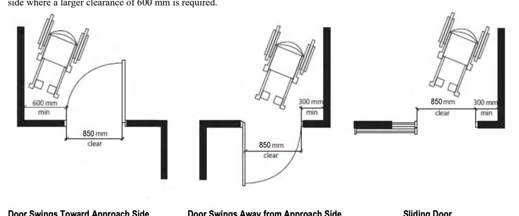
A-3.8.3.3.(11)(b) Doors in a Series. Copy linkAdd bookmark
Where there are doors in a series such as an entry or washroom vestibule, there must be a full 1500 mm diameter turning circle or a linear dimension of 1500 mm provided within the vestibule that is clear of the door swing to ensure that persons using wheelchairs or other mobility devices can close the door behind them before proceeding through the next door in the series.
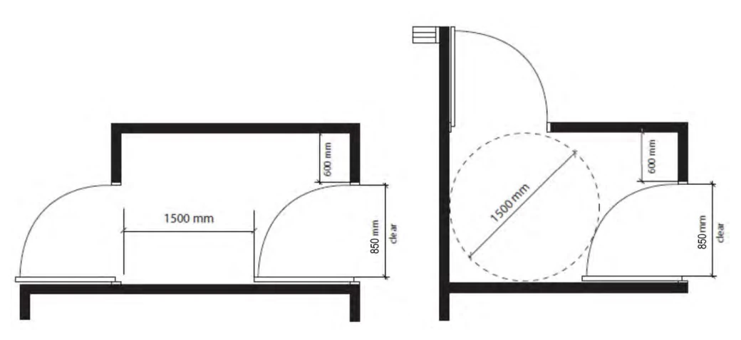
A-3.8.3.3.(17)(c) Vertical Power Door Operators. Copy linkAdd bookmark
The height range permitted for the location of a power door operators in Subclause 3.8.3.3.(17)(c)(ii) allows for the installation of vertical power door operators, either wall- or floor-mounted, that can be operated by a closed fist, a foot or other pressure anywhere within the height of the door operating device.
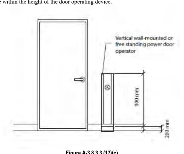
A-3.8.3.3.(18) Proximity Scanners as Door Operators. Copy linkAdd bookmark
Where a proximity scanner is utilized it must be set to scan a lower height to ensure that a person using a seated mobility device will trigger the opening of the door.
A-3.8.3.3.(19)(b) Manual Door Operators. Copy linkAdd bookmark
The door opening device referred to in Clause 3.8.3.3.(19)(b) is not required to be a power door operator. A manual door opener with lever handles will meet the intent of the Code.
A-3.8.3.4.(1)(b) Ramp Slopes. Copy linkAdd bookmark
Although Article 3.8.3.4. permits slopes on ramps as great as 1 in 12 for distances of up to 9 m, gradients of 1 in 20 are safer and less strenuous. When limited space is available, as may be the case during renovations, ramps of up to 1 in 12 should be restricted to lengths not exceeding 3 m whenever possible.
A-3.8.3.4.(1)(c) Landing Design at Doorways Leading to Ramps. Copy linkAdd bookmark
A level landing surface at doorways leading to ramps provides a level and stable surface for people using wheeled mobility devices and other mobility aids to stop and manoeuver clear of the door swing.
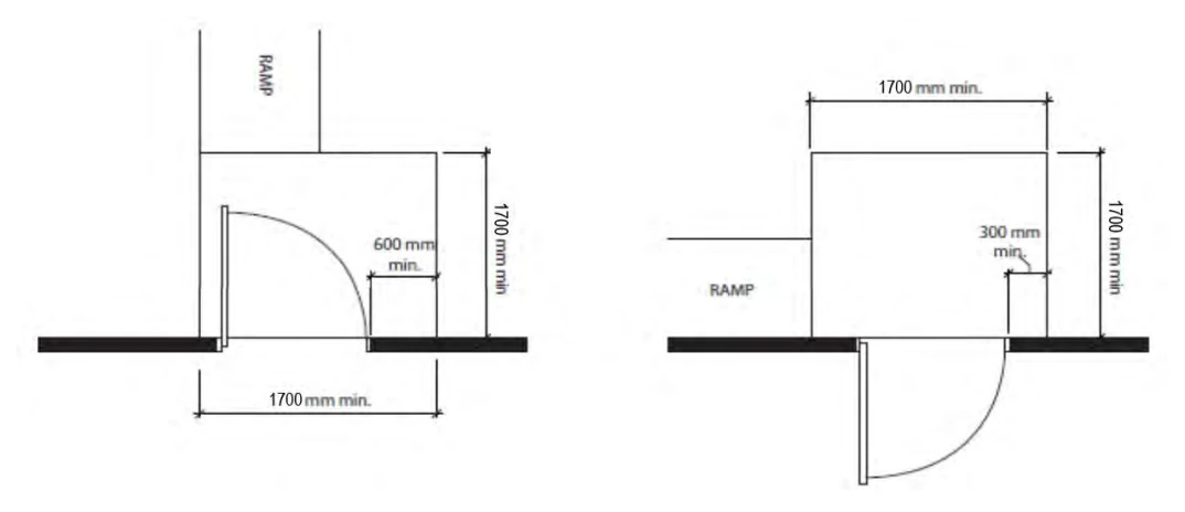
A-3.8.3.4.(2) Fixed Seating on Sloped Floors. Copy linkAdd bookmark
In an assembly room with fixed seating on a sloped floor, such as a theatre, the limitation on floor slope is intended to apply only to the required barrier-free access leading to spaces for persons using wheelchairs described in Sentence 3.8.2.1.(3) and not to aisles and portions of floors serving only fixed seating for ambulatory persons.
A-3.8.3.4.(3) Sloped Floors. Copy linkAdd bookmark
A floor with a slope of 1:20 or less need not be designed as a ramp.
A-3.8.3.6.(1)(c) Locating Wheelchair Spaces, Adaptable and Companion Seating. Copy linkAdd bookmark
People with disabilities who require either a wheelchair space or an adaptable seat may attend an event with a companion who needs no special seating accommodation. For that reason, the companion seat required beside a wheelchair space is intended to be a standard seat provided for the facility.
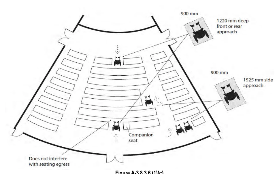
A-3.8.3.7.(1) Assistive Listening Systems. Copy linkAdd bookmark
Examples of assistive listening systems include FM, infrared and induction loop systems. However, the technology in this field is advancing rapidly; as such, other types of assistive listening systems could be considered in the design of a space. In choosing the most appropriate system, a number of factors must be taken into account including cost, installation and maintenance requirements, suitability for the intended user or audience, ease of operation, and the need for privacy. Information on designers and suppliers of such systems can be obtained from the Canadian Hearing Society. The intent of Article 3.8.3.7. is to provide clear communication where information, goods or services are provided to the public.
Wireless sound transmission systems, such as FM, infrared or magnetic induction loop, improve sound reception for the hard of hearing by providing amplification which can be adjusted by each user while blocking out unwanted background noise. These systems transmit a signal that is picked up by special receivers available for use by people with a hearing impairment, whether or not they use a hearing aid. Neither system interferes with the listening enjoyment of others.
The transmitter can be jacked into an existing P.A. system amplifier or used independently with microphones. The induction loop system (See Figure A-3.8.3.7.(1)-C) requires users to sit in the area circumscribed by the loop; though installation of the loop is relatively simple, the installer should be knowledgeable about these systems if proper functioning is to be achieved. FM or infrared systems can be designed to broadcast signals which cover the entire room and thus do not restrict seating to any one area. Figures 3.8.3.7.(1)-A and 3.8.3.7.(1)-B show the general configuration of FM and infrared systems. Although portable systems (FM in particular) are available, these are best suited to small audiences. Generally, the systems installed in church halls, auditoria, theatres and similar places of assembly are not easily portable, as they are installed in a fixed location by a sound technician and form an integral part of the P.A. system of the room or building.
Hard wired systems (where a jack is provided at a particular seat) will not meet this requirement unless adequate provisions are made to accommodate persons with hearing aids. In choosing the most appropriate system, a number of factors must be taken into account including cost, installation and maintenance, suitability to the audience, ease of operation and the need for privacy. Information on designers and suppliers of these systems may be obtained from such organizations as the Canadian Hearing Society.
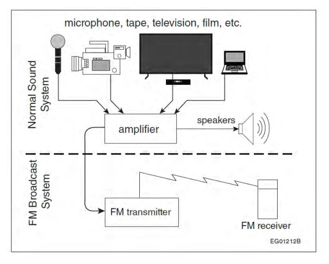
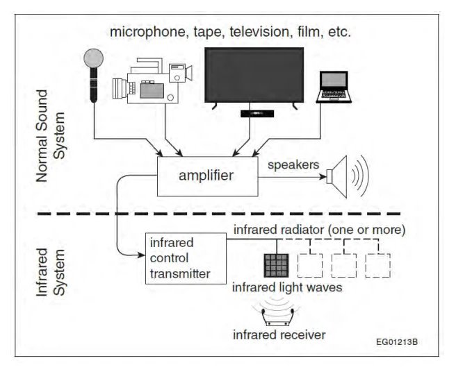
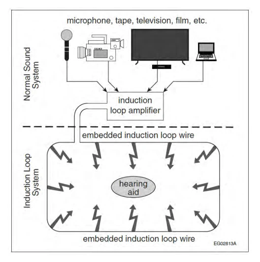
A-3.8.3.7.(2) Assistive Listening Systems and Adaptive Technologies. Copy linkAdd bookmark
The intent of Sentence 3.8.2.9.(2) is to require that at least one counter with an assistive listening system or adaptive technology be provided at each group of service counters providing the same exchange of information, goods or services. For example, in a stadium with ticket counters at multiple building entrances, at least one ticket counter at each entrance should be equipped with an assistive listening system or adaptive technology.
A-3.8.3.8.(1)(a) Water Closet Stalls. Copy linkAdd bookmark
The wheelchair turning circle within the stall may not overlap space of an inward swinging door or the area below plumbing fixtures.
A-3.8.3.8.(1)(c)(iii) Water Closet Stalls. Copy linkAdd bookmark
Doors to water closet stalls for persons with disabilities should swing outward and preferably against a side wall.
A-3.8.3.8.(1)(c)(v) Washroom Stall Door Pulls. Copy linkAdd bookmark
The purpose of the door pull mounted on both sides of the stall door is to assist those with limited arm strength to open and close the door. The pull should be located close to the latch side on both the inside and outside surfaces of the door. Pulls mounted close to the latch side require less strength to pull the door open or closed than a pull located close to the hinge side. The door pull should consist of a D-shaped handle mounted horizontally. The centre lines are the lines drawn through the long axis and the short axis of the handle. In the horizontal position, the centerline of the short or transverse axis must be located at between 200 mm and 300 mm from the latch side of the door, and the long or longitudinal axis must be located between 900 mm and 1 100 mm from the floor.
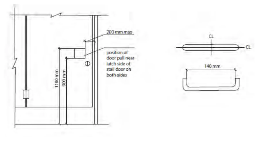
A-3.8.3.8.(1)(f) Washroom Clearances. Copy linkAdd bookmark
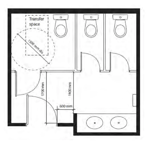
A-3.8.3.8.(2)(b) Transfer Space on Both Sides of Water Closet. Copy linkAdd bookmark
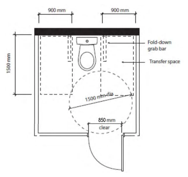
A-3.8.3.8.(3) Additional Grab Bars. Copy linkAdd bookmark
Designers may exceed the minimum requirements found in the Building Code and specify the installation of additional grab bars in other locations. These additional grab bars may be of different configurations and can be installed in other orientations.
A-3.8.3.8.(5) L-Shaped Grab Bar. Copy linkAdd bookmark
L-shaped grab bars provide greater support for people who rely on grab bars to assist them in transferring to and from a standing or seated position. Diagonally mounted grab bars may not be suitable for the downward force necessary for support or for pulling upward. Hands can slip along the bar if it is set in a diagonal position. The use of two straight grab bars located at a 90° angle to one another is not permitted.
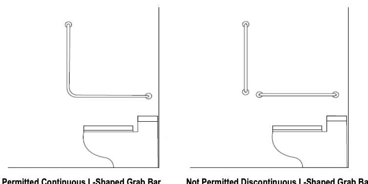
A-3.8.3.8.(8) Fold-Down Grab Bars. Copy linkAdd bookmark
A fold-down grab bar is required to resist a load of 1.3 kN applied either vertically or horizontally and will require blocking in the wall so that the grab bar remains anchored to the wall when in use.
A-3.8.3.8.(10) Ambulatory Water Closet Stalls. Copy linkAdd bookmark
An ambulatory water closet stall is designed to accommodate people requiring some mobility assistance using aids such as canes or crutches but who do not use wheelchairs. Ambulatory stalls include features such as a higher water closet seat height, grab bars and some additional space for mobility aids such as a cane. A door pull should be provided on both faces of the stall door.
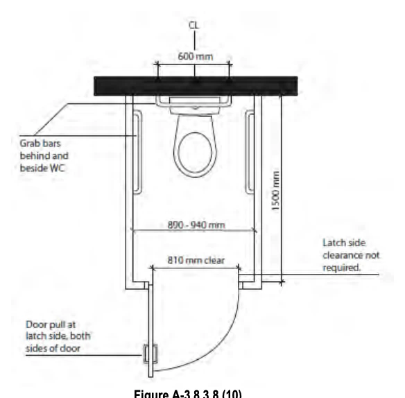
A-3.8.3.9. Water Closets. Copy linkAdd bookmark
Article 7.2.2.5. applies to water closets referenced in Articles 3.8.3.8., 3.8.3.9. and 3.8.3.12.
A shelf or projection should not be located behind a water closet such that it could present a hazard.
A-3.8.3.9.(1) Water Closets. Copy linkAdd bookmark
Wall-mounted water closets or floor models with receding bases are preferable because they provide the least amount of obstruction.
A-3.8.3.9.(1)(c) Back Support at Water Closets. Copy linkAdd bookmark
The purpose of the back support is to reduce the chance of imbalance or injury caused by a user leaning against exposed flush valves or pipes. A toilet seat lid, where provided, may be a suitable back support.
A-3.8.3.10. Barrier-Free Urinals. Copy linkAdd bookmark
Where provided, barrier-free urinals require both properly mounted and supported grab bars and privacy screens. Privacy screens alone should not be used as both a privacy and support element.
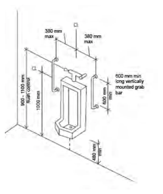
A-3.8.3.11. Washroom Accessories. Copy linkAdd bookmark
Washroom accessories for barrier-free water closets and lavatories must be located within arm’s reach of a person in a seated position. Placement of towel dispensers and hand dryers should not require that a person seated in a wheelchair must travel beyond the reach range of the lavatory to dry his or her hands.
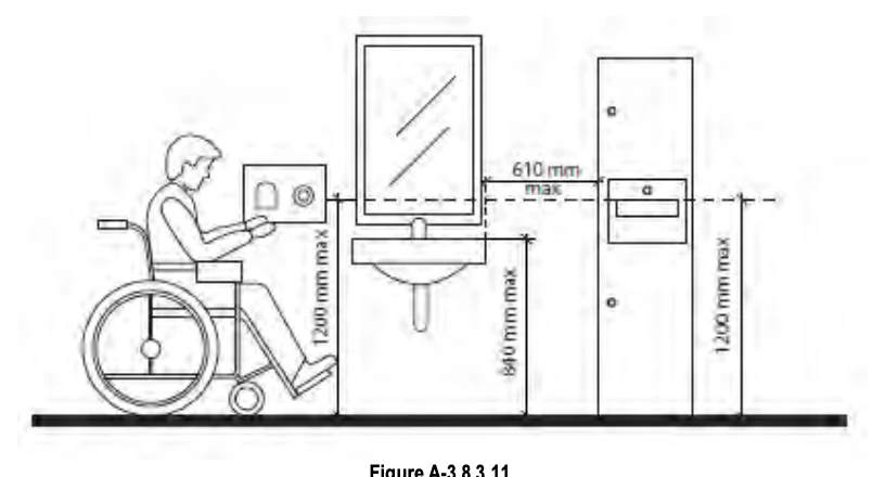
A-3.8.3.11.(1)(c) Clearances Beneath a Lavatory. Copy linkAdd bookmark
Barrier-free lavatories require sufficient knee and toe clearance below to permit a person in a wheelchair to move close enough to the faucet to easily access the water stream.
In order to meet the clearances contained in this Clause, and depending on the lavatory to be installed, it may be necessary to install an offset P.O. lavatory drain.
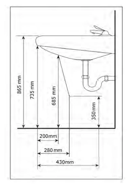
A-3.8.3.11.(1)(d) Pipe Protection. Copy linkAdd bookmark
The pipes referred to in Clause 3.8.3.11.(1)(d) include both supply and waste pipes. The hazard can be prevented by insulating the pipes, by locating the pipes in enclosures, or avoided by limiting the temperature of the hot water to a maximum of 43°C.
A-3.8.3.11.(1)(f) Clear Space at Lavatory. Copy linkAdd bookmark
The clear space required for the wheelchair user to pull into the fountain may overlap with an adjacent barrier-free path of travel but should not prevent other building users from passing when the barrier-free lavatory is in use.
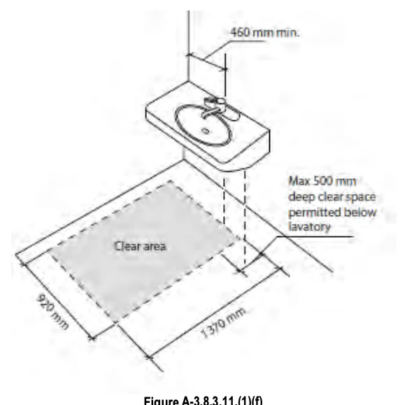
A-3.8.3.12.(1)(d) Transfer Space. Copy linkAdd bookmark
The transfer space beside a water closet or the approach space at a lavatory must be a clear space with no obstruction or potential obstruction of the space from adjacent elements such as a fold-down change table, or other fixture. The exception to this would be a fold-down grab bar where provided. If a fold-down change table is not returned to the fold-up position after use, the next user of the space should not be inconvenienced from using the water closet or lavatory due to the transfer or approach spaces being blocked.
A-3.8.3.12.(1) and (3) Universal Washroom. Copy linkAdd bookmark
Unobstructed areas in front of the lavatory, in front of the water closet and on one side of the water closet are necessary for manoeuverability of a wheelchair. The door swing may overlap the turning circle within the universal washroom as long as there is sufficient space for a wheelchair user to manoeuver to clear the door and close the door from a front approach position.
The space for an adult size change table may encroach upon the 1700 mm turning circle only where the change table is movable and is not permanently fixed or stored within the washroom. In that case the table, such as a hospital gurney is brought into the washroom when needed and removed after use. A permanently fixed table may not be appropriate for certain building occupancies due to operational and maintenance considerations.
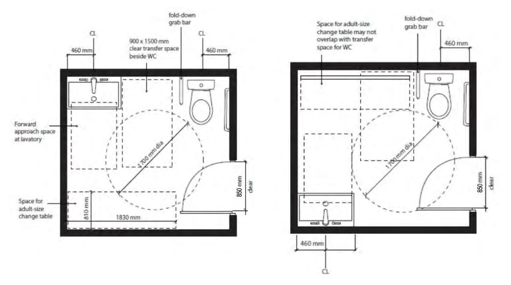
A-3.8.3.12.(2) Emergency Call System. Copy linkAdd bookmark
The purpose of the emergency call system is to notify other building occupants that a person using the universal washroom requires assistance. The visual signal and alarm should be different from the building fire and smoke alarms and visual signals, where installed, as this call system is for personal, not building, emergencies.
The emergency call button is intended to provide a local visual signal outside of the washroom to alert others that someone in the washroom needs assistance. It is not required to be linked to a central monitoring station. Where central monitoring is not provided, such as in the case of a small building or a standalone washroom in a park, an additional sign informing the washroom users that there is no central monitoring may be appropriate.
A-3.8.3.12.(6) Universal Washrooms for Small Buildings. Copy linkAdd bookmark
The permission for a smaller universal washroom to be provided in small buildings recognizes the limited space available for construction of service and amenity spaces while still balancing available space with the needs of people with disabilities.
A-3.8.3.13.(1) Minimum Number of Barrier-Free Showers. Copy linkAdd bookmark
The intent of the requirement for one or more barrier-free showers in a group of showers is to address the increased demand for accessible facilities in publicly accessible buildings such as arenas, community recreation centres and private health and fitness facilities where the accessible shower stall is located in the same room as non-accessible showers. It is not the intent of the Code to require single shower stalls or single private use showers that are part of a private office suite to be barrier-free accessible.
A-3.8.3.13.(2)(b) Clear Space at Entrances to Showers. Copy linkAdd bookmark
The clear space at the entrance to a shower may be encroached upon by fixtures such as a wall hung sink which does not interfere with the leg rests of the wheelchair. However, this sink could restrict movement for persons who need to make a lateral transfer if it were installed at the seat end of the shower.
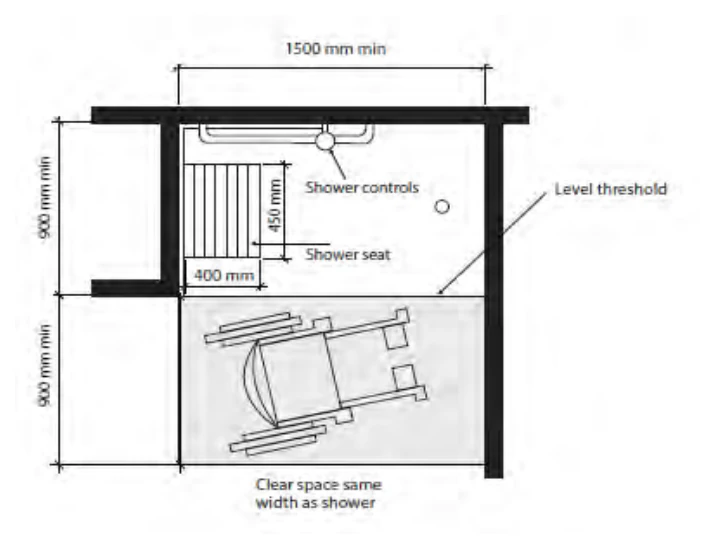
A-3.8.3.13.(2)(f) and (g) Shower Seat and Grab Bars. Copy linkAdd bookmark
Only one grab bar is required, to be installed on the wall next to the seat; a grab bar behind the seat prevents the user from leaning against the wall, while one located on the wall opposite the seat cannot be reached from the seated position.
The use of two straight grab bars installed at a 90° angle to one another is not acceptable. The Code requires a continuous L-shaped grab bar. The seat itself may be used in conjunction with the bar for transfer. If design flexibility is required, fold away grab bars may be used as an alternative.
A grab bar installed within a barrier-free shower stall on the same wall as the shower controls should have 900 mm long horizontal and vertical components.
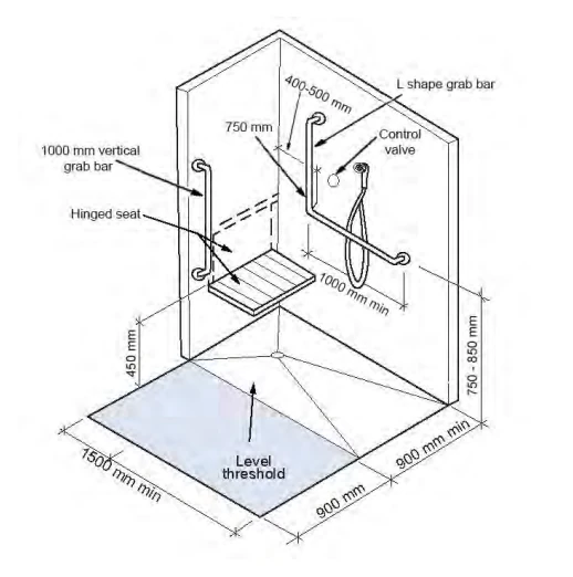
A-3.8.3.13.(4) Universal Dressing and Shower Rooms. Copy linkAdd bookmark
A universal dressing and shower room is a barrier-free space that contains a shower and a space for dressing for one person and their care attendant(s) and provides privacy, regardless of gender. It is intended that a universal dressing and shower room be available within close proximity to each bank of showers in a floor area. In cases where only one shower is provided, a universal dressing and shower room would satisfy the requirement.
A-3.8.3.13.(5)(f) Grab Bar at Bench. Copy linkAdd bookmark
Where a bench in a universal dressing and shower room is located adjacent to a wall, it is recommended that a grab bar be installed to assist users in transferring to the bench.
A-3.8.3.13.(7) Showers and Bathtubs. Copy linkAdd bookmark
The grab bars and their mounting position must facilitate getting in and out of the bathtub from a seated or standing position, as appropriate, to limit the need for twisting the body.
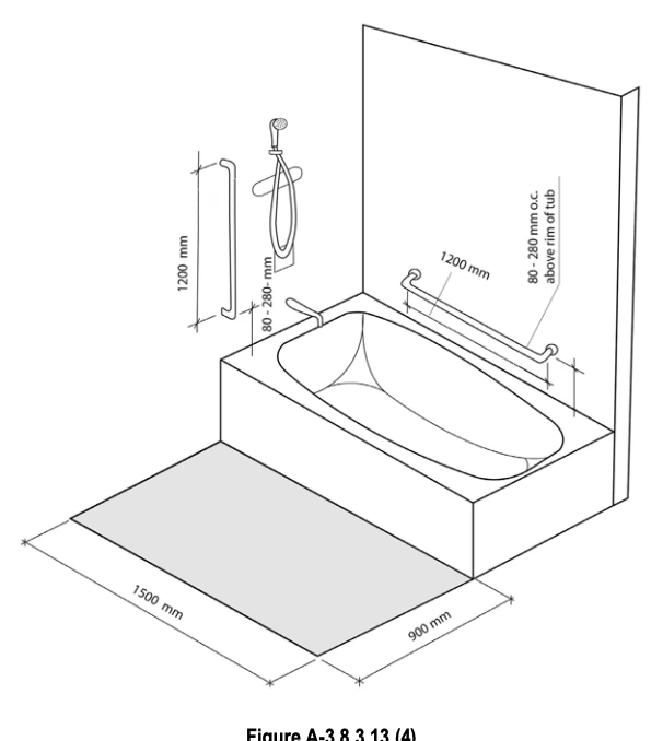
A-3.8.3.14.(1) Service Counters. Copy linkAdd bookmark
It is not intended that all counters be barrier-free, but that sufficient barrier-free counter space be available. Examples of counters that should be barrier-free include check-in counters and those in financial institutions and reception areas as well as any counter at which processing and signing of documents takes place. The provision is not intended to apply to work surfaces in industrial occupancies.
A-3.8.3.14.(2)(c) Knee Space at Service Counters. Copy linkAdd bookmark
Where forward-facing interaction with a person is required, the knee space requirement of Clause 3.8.3.20.(1)(c) applies to both sides of the service counter to ensure accessibility for both service providers and those receiving services.
A-3.8.3.15. Telephone Shelves or Counters. Copy linkAdd bookmark
Built-in shelves or counters for public telephones must be designed to accommodate persons using text telephones (TT). These devices may also be referred to as teletypewriters (TT) or telecommunication devices for the deaf (TDD). These devices require a level surface at least 500 mm wide by 350 mm deep with no obstruction above that space within 250 mm. If a wall-hung telephone or other obstruction extends to less than 250 mm from the shelf or counter, an equivalent clear space must be provided on either side of each telephone.
At least one telephone should be equipped with a volume control on a receiver that generates a magnetic field compatible with the T-switch of a hearing aid. The lower portion of the shelf or counter is intended for persons using a wheelchair; therefore, all parts of the operating mechanism of the telephone above this portion should be within the reach of a wheelchair user.
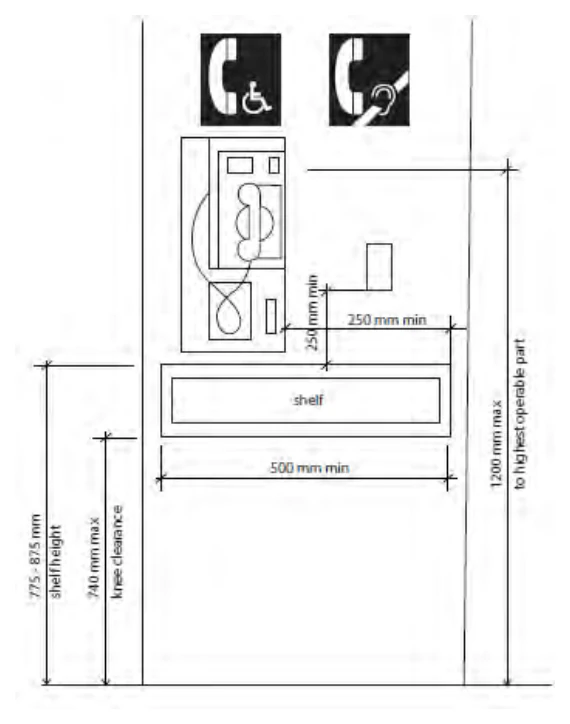
A-3.8.3.16. Drinking Fountains. Copy linkAdd bookmark
Accessible drinking fountains require sufficient knee and toe clearance below to permit a person in a wheelchair to move close enough to the fountain to easily access the water stream. The 700 mm deep clear space in addition to the fountain depth of 450 mm minimum is required for the wheelchair user to pull into the fountain. That approach space may overlap with an adjacent barrier-free path of travel but should not prevent other building users from passing when the drinking fountain is being used.
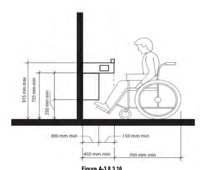
A-3.8.3.16A.(2)(b) and (d) Water-Bottle Filling Stations. Copy linkAdd bookmark
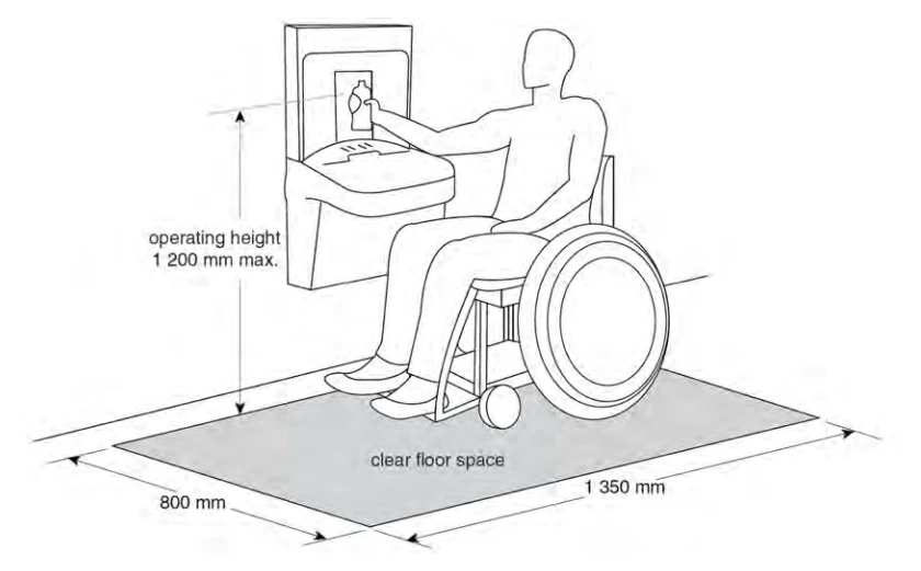
A-3.9.3. Portable Classrooms. Copy linkAdd bookmark

Distance between classrooms: 6 m or more 3.2.2. applies to each classroom 3.2.3. does not apply between classrooms
Extinguisher required Access; street; hydrant; fire alarm; - not required

Distance between classrooms: less than 6 m³.2.2. applies to each classroom 3.2.3. applies to each classroom i.e. rating and construction of facing walls determined by limiting distance
Extinguisher required Access; street; hydrant; fire alarm; - not required

Distance between classrooms: less than 6 m No. of classrooms in group: 6 max. Distance between groups: not less than 12 m³.2.2. applies to each group 3.2.3. does not apply between classrooms within a group if the facing walls have a rating of 45 min, on the inside 3.2.3. applies between groups
Extinguisher required Access; street; hydrant; fire alarm - not required

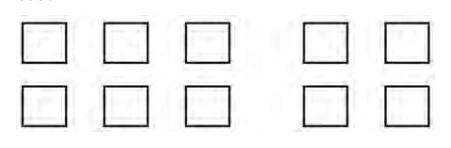
Distance between classrooms: less than 6 m No. of classrooms in group: 6 max. Distance between groups: not less than 12 m³.2.2. applies to each group 3.2.3. does not apply between classrooms within a group 3.2.3. applies between groups
Extinguisher required Fire alarm required (extension of main system) Access; street; hydrant; - not required

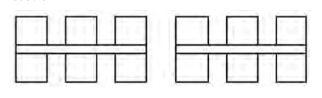
Distance between classrooms: less than 6 m No. of classrooms in group: 6 max. Distance between groups: not less than 12 m³.2.2. applies to each group 3.2.3. does not apply between classrooms within a group 3.2.3. applies between groups
Extinguisher required Fire alarm required (extension of main system) Access; street; hydrant; - not required
All other cases require:
- - Fire extinguisher
- - Access
- - Street
- - Hydrant
- - Fire alarm: extension of existing system
A-3.11.3.1.(9)(a) Barrier-Free Path of Travel at Pool Deck. Copy linkAdd bookmark
The barrier-free path of travel throughout the pool deck area may be included in the 1800 mm wide pool deck space. The width of the barrier-free path of travel must not be reduced where a column or other obstruction interrupts the pool deck space.
A-3.11.3.1.(14) Tactile Indicator at Pool Deck. Copy linkAdd bookmark
The tactile indicator at the of the pool deck, signals a warning to people with no or low vision that they have reached the water’s edge. The tactile indicator may be built-in or applied but must not present a tripping hazard. The indicator should be a continuous band installed parallel to the outside edge of the gutter around the pool perimeter.
A-3.11.3.2.(1) Outdoor Pool Deck. Copy linkAdd bookmark
Where an outdoor pool deck is provided, a barrier-free path that is an exterior walk is required between the building and the outdoor pool, including access from change rooms and showers, and throughout the pool deck area.
A-3.11.3.3.(4) Pool Lift Space Requirements. Copy linkAdd bookmark
The clear space required to transfer from a wheelchair to the pool lift may overlap the required barrier-free path of travel within the pool deck.
A-3.11.5.1.(4)(b) Ramps into Public Swimming Pools. Copy linkAdd bookmark
Despite the requirement that the hard surface area piercing the pool deck and leading to a submerged ramp must be at least 750 mm wide, it is recommended that the clear width of the access point to the ramp be at least the same width of the ramp and consistent with Clause 3.8.3.4.(1)(d).
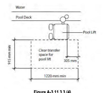
A-3.12.3.2.(3) and (4) Transfer Wall at Public Spa. Copy linkAdd bookmark
A transfer wall design can be accommodated where the spa is raised above the pool deck enabling a wheelchair user to make a horizontal transfer from the wheelchair seat to the top surface of the transfer wall and directly accessing the water on the other side of the wall.
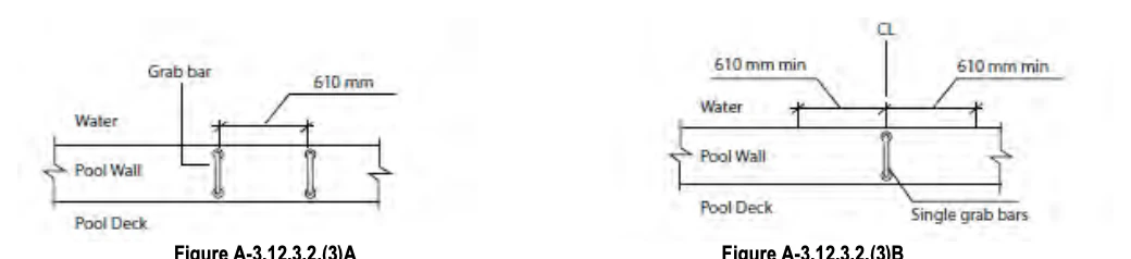
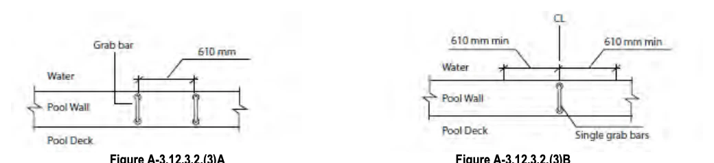
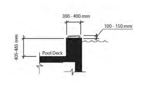
A-3.14. Tents and Air-Supported Structures. Copy linkAdd bookmark
The requirements in this Subsection are intended to be limited to certain types of structure. For instance, the word “tent” as used in the Code is intended to refer to a temporary shelter which is used at an open air event such as a fair or an exhibition. A tent will normally be constructed of a fabric held up by poles and attached to the ground by ties. The requirements for tents, however, are not intended to be applied to fabric structures located on buildings.
The term “air-supported structure”, as used in the Code, refers to an envelope which is held up by air pressure alone and which is erected on the ground or on a building. The structure will usually require ballast or a positive anchorage system around the entire perimeter to secure it to the ground or building structure.
A-3.16.1.7.(7) Exits and Means of Egress from Shelf and Rack Storage Systems. Copy linkAdd bookmark
The fundamental principle of providing sufficient exits and means of egress from a shelf and rack storage system is to have the occupants reach an open public thoroughfare, a separate building, or an exterior open space protected from fire exposure from the building and having an access to an open public thoroughfare before the environment in the building becomes life threatening.
In addition to the time-based egress calculation, the professional engineer or architect undertaking the time-based egress analysis, must also undertake a detailed fire dynamics evaluation of the occupancy to determine when critical life threatening levels are reached. Temperature, toxic conditions and psycho-physiological characteristics of the occupants will play an important roll in the analysis.
A-4.1.1.3.(1) Structural Integrity. Copy linkAdd bookmark
The requirements of Part 4, including the CSA design standards, generally provide a satisfactory level of structural integrity. Additional considerations may, however, be required for building systems made of components of different materials, whose interconnection is not covered by existing CSA design standards, buildings outside the scope of existing CSA design standards, and buildings exposed to severe accidental loads such as vehicle impact or explosion. Further guidance can be found in the Commentary entitled “Structural Integrity” in the “Structural Commentaries (User's Guide – NBC 2020: Part 4 of Division B)”.
A-4.1.1.3.(2) Serviceability. Copy linkAdd bookmark
Information on serviceability can be found in the Commentary entitled “Deflection and Vibration Criteria for Serviceability and Fatigue Limit States” in the “Structural Commentaries (User's Guide – NBC 2020: Part 4 of Division B)”.
A-4.1.1.5.(2) Structural Equivalents. Copy linkAdd bookmark
Sentence 4.1.1.5.(2) provides for the use of design methods not specified in Part 4, including full-scale testing and model analogues. This provision is usually used to permit the acceptance of newer and innovative structures or to permit the acceptance of model tests such as those used to determine structural behaviour, or snow or wind loads. Sentence 4.1.1.5.(2) specifically requires that the level of safety and performance be at least equivalent to that provided by design to Part 4 and requires that loads and designs conform to Section 4.1.
Sentence 4.1.1.5.(2) and the provision for alternative solutions stated in Clause 1.2.1.1.(1)(b) of Division A are not intended to allow structural design using design standards other than those listed in Part 4. The acceptance of structures that have been designed to other design standards would require the designer to prove to the appropriate authority that the structure provides the level of safety and performance required by Clause 1.2.1.1.(l)(b) of Division A. The equivalence of safety and performance can only be established by analyzing the structure for the loads and load factors set out in Section 4.1. and by demonstrating that the structure at least meets the requirements of the design standards listed in Sections 4.3. and 4.4.
A-4.1.2.1. Loads and Effects. Copy linkAdd bookmark
Information on the definitions can be found in the Commentary entitled “Limit States Design” in the “Structural Commentaries (User's Guide – NBC 2020: Part 4 of Division B)”.
A-4.1.2.1.(1) Temperature Changes. Copy linkAdd bookmark
Information on effects due to temperature changes can be found in the Commentary entitled “Effects of Deformations in Building Components” in the “Structural Commentaries (User's Guide – NBC 2020: Part 4 of Division B)”.
A.4.1.2.1.(3) Major Occupancies. Copy linkAdd bookmark
In a building containing more than one major occupancy and classified in more than one Importance Category, the classification of each independent structural system shall be the same as for any part of the building that is dependent on that structural system and for the highest usage group according to Table 4.1.2.1.
A-Table 4.1.2.1.B. Importance Categories for Buildings. Copy linkAdd bookmark
Low Importance Category BuildingsCopy linkAdd bookmark
A minor storage building is an example of a Low Importance Category building.
Low-human-occupancy farm buildings with an occupant load of 1 person or less per 40 m2 of floor area are also examples of Low Importance Category buildings.
Normal Importance CategoryCopy linkAdd bookmark
Most buildings will fall into the Normal Importance Category.
The following types of buildings may be classified in the Normal Importance Category: buildings that are equipped with secondary containment of dangerous goods, including, but not limited to, double-walled tanks, dikes of sufficient size to contain a spill, and other means to contain a spill or a blast within the property boundary of the facility and prevent the release of harmful quantities of contaminants to the air, soil, groundwater, surface water or atmosphere, as the case may be.
High Importance CategoryCopy linkAdd bookmark
The following buildings may contain sufficient quantities of dangerous goods to be classified in the High Importance Category:
- petrochemical facilities,
- fuel storage facilities (other than those required for post-disaster use), and
- manufacturing or storage facilities containing dangerous goods.
Information on community centres can be found in the Commentary entitled “Limit States Design” in the “Structural Commentaries (User's Guide – NBC 2020: Part 4 of Division B)”.
Post-Disaster Importance CategoryCopy linkAdd bookmark
Before classifying a building as a post-disaster building, Code users should consider the intent of the classification and look beyond the name of the building. For example, a building that is named “ABC Treatment” but is used for emergency care should be considered as a hospital and, as such, classified as a post-disaster building. Conversely, a building named “XYZ Hospital” that is only used for walk-in medical services could be classified as a Normal Importance Category building.
A-4.1.2.2.(1) Loads Not Listed. Copy linkAdd bookmark
The intent of Sentence 4.1.2.2.(1) is to draw attention to the fact that there are loads, forces and effects that need to be considered in addition to those specified in the Code. These loads, forces and effects will vary in need, application, and magnitude for each use and location. Some may result from environmental considerations (e.g., ice accretion, wave and ice action, water flow) while others will result from the use and occupancy of the facility (e.g., dangerous goods storage, manufacturing and mining operations). The reasonable determination of the probability, type and magnitude of project-specific loads must be assessed by a knowledgeable project team that includes the building owner/operator and experienced design professionals, and incorporated into the design where deemed necessary to maintain the safety and integrity of the facility.
In recent years, security issues have prompted the consideration of loads and effects due to improvised explosive devices and other methods of sabotage. Consideration of these loads is driven by operational and public safety requirements, and their incorporation in the design is not considered a mandatory provision of the Code.
A-4.1.3. Limit States Design. Copy linkAdd bookmark
Information on limit states design can be found in the Commentary entitled “Limit States Design” in the “Structural Commentaries (User's Guide – NBC 2020: Part 4 of Division B)”.
A-4.1.3.2.(2) Load Combinations. Copy linkAdd bookmark
Load Combination EquationsCopy linkAdd bookmark
The load combinations in Tables 4.1.3.2.-A and 4.1.3.2.-B apply to most situations for loadbearing building structures. Guidance on special situations such as load combinations for fire resistance and building envelopes is given in the Commentary entitled “Limit States Design” in the “Structural Commentaries (User's Guide – NBC 2020: Part 4 of Division B)”.
Load Cases and Crane Load EffectsCopy linkAdd bookmark
The load combinations in Table 4.1.3.2.-A are to be evaluated for structures with crane load effects for the scenario where the crane loads are zero, and for structures without crane loads. The load combinations in Table 4.1.3.2.-B are to be evaluated for structures with crane loads for the scenario where the crane load effects are other than zero.
Crane LoadsCopy linkAdd bookmark
Crane-supporting structures that have cranes in multiple parallel bays should be designed for the maximum vertical crane load with the cranes positioned for the most critical effect in conjunction with a lateral load with each crane in turn positioned for the most critical effect. For load combinations that include crane loads, additional guidance can be found in CISC/ICCA 2013, “Crane-Supporting Steel Structures: Design Guide”.
A-4.1.3.2.(4) Effects of Lateral Earth Pressure, H, Pre-Stress, P, and Imposed Deformation, T, in Design Calculations. Copy linkAdd bookmark
Effects of Lateral Earth Pressure, H, in Design CalculationsCopy linkAdd bookmark
For common building structures below ground level, such as walls, columns and frames, 1.5 H is added to load combinations 2 to 4. For cantilever retaining wall structures, see the Commentary entitled “Limit States Design” in the “Structural Commentaries (User's Guide – NBC 2020: Part 4 of Division B)”.
Effects of Pre-Stress, P, and Imposed Deformation, T, in Design CalculationsCopy linkAdd bookmark
For structures and building envelopes designed in accordance with the requirements specified in the standards listed in Section 4.3., with the exception of Clauses 8 and 18 of CSA A23.3, P and T need not be included in the load combinations of Table 4.1.3.2.-A. For structures not within the scope of the standards listed in Section 4.3., including building envelopes, P and T must be taken into account in the design calculations. For recommended load combinations including T, see the Commentary entitled “Limit States Design” in the “Structural Commentaries (User's Guide – NBC 2020: Part 4 of Division B)”.
A-4.1.3.2.(5) Overturning, Uplift or Sliding. Copy linkAdd bookmark
Information on overturning, uplift and sliding can be found in the Commentary entitled “Limit States Design” in the “Structural Commentaries (User's Guide – NBC 2020: Part 4 of Division B)”.
A-4.1.3.3.(1) Failure Due to Fatigue. Copy linkAdd bookmark
Failure due to fatigue of building structures referred to in Section 4.3. and designed for serviceability in accordance with Article 4.1.3.6. is, in general, unlikely except for girders supporting heavily used cranes, on which Article 4.1.5.11. provides guidance.
A-4.1.3.3.(2) Vibration Effects. Copy linkAdd bookmark
Guidance on vibration effects can be found in the Commentary entitled “Deflection and Vibration Criteria for Serviceability and Fatigue Limit States” in the “Structural Commentaries (User's Guide – NBC 2020: Part 4 of Division B)”.
A-4.1.3.4.(1) Loads and Load Combinations for Serviceability. Copy linkAdd bookmark
The loads and load combinations for serviceability depend on the serviceability limit states and on the properties of the structural materials. Information on loads and load combinations for the serviceability limit states, other than those controlled by deflection, can be found in the Commentary entitled “Deflection and Vibration Criteria for Serviceability and Fatigue Limit States” in the “Structural Commentaries (User's Guide – NBC 2020: Part 4 of Division B)”.
A-Table 4.1.3.4. Acceleration Due to Vibrations. Copy linkAdd bookmark
Information on the determination of acceleration due to vibrations resulting from loads L and W can be found in the Commentary entitled Wind Load and Effects in the “Structural Commentaries (User's Guide – NBC 2020: Part 4 of Division B).”
A-4.1.3.5.(1) Deflections. Copy linkAdd bookmark
Serviceability criteria for deflections that cause damage to non-structural building components can be found in the standards listed in Section 4.3. Information on deflections can be found in the Commentary entitled “Deflection and Vibration Criteria for Serviceability and Fatigue Limit States” in the “Structural Commentaries (User's Guide – NBC 2020: Part 4 of Division B)”. Information on loads and load combinations for calculating deflection can be found in the Commentary entitled “Limit States Design” in the “Structural Commentaries (User's Guide – NBC 2020: Part 4 of Division B)”.
A-4.1.3.5.(3) Lateral Deflection of Buildings. Copy linkAdd bookmark
The limitation of 1/500 drift per storey may be exceeded if it can be established that the drift as calculated will not result in damage to non-structural elements. Information on lateral deflection can be found in the Commentary entitled “Wind Load and Effects” in the “Structural Commentaries (User's Guide – NBC 2020: Part 4 of Division B)”.
A-4.1.3.6.(1) Floor Vibration. Copy linkAdd bookmark
Information on floor vibration can be found in the Commentary entitled “Deflection and Vibration Criteria for Serviceability and Fatigue Limit States” in the “Structural Commentaries (User's Guide – NBC 2020: Part 4 of Division B)”. Information on loads and load combinations for the calculation of vibration can be found in the Commentary entitled “Limit States Design” in the “Structural Commentaries (User's Guide – NBC 2020: Part 4 of Division B)”.
A-4.1.3.6.(2) Floor Vibrations Caused by Resonance with Operating Machinery or Equipment. Copy linkAdd bookmark
Guidance on floor vibration effects caused by operating machinery and equipment can be found in the Commentary entitled Deflection and Vibration Criteria for Serviceability and Fatigue Limit States in the “Structural Commentaries (User's Guide – NBC 2020: Part 4 of Division B)”.
A-4.1.3.6(3) Dynamic Analyses of Floor Vibrations. Copy linkAdd bookmark
Information on a dynamic analysis of floor vibrations from rhythmic activities can be found in the Commentary entitled “Deflection and Vibration Criteria for Serviceability and Fatigue Limit States” in the “Structural Commentaries (User's Guide – NBC 2020: Part 4 of Division B)”.
A-4.1.3.6.(4) Lateral Vibration Under Wind Load. Copy linkAdd bookmark
Information on lateral vibrations and accelerations under dynamic wind loads can be found in the Commentary entitled “Wind Load and Effects” in the “Structural Commentaries (User's Guide – NBC 2020: Part 4 of Division B)”.
A-4.1.4.1.(2) Permanent Partitions Fixed to the Structure. Copy linkAdd bookmark
Partitions in residential buildings, including condominiums, apartments and hotels, are typically permanent and fixed to the structure. In such cases, the weight of partitions referred to in Clause 4.1.4.1.(1)(c) is the actual weight of the partitions that are shown on the drawings.
A-4.1.4.1.(3) Partitions Not Shown on the Drawings. Copy linkAdd bookmark
The potential locations of partitions in work areas, such as offices, are not typically shown on the drawings. For such areas, a partition weight allowance must be considered based on the anticipated weight and location of partitions, but not less than 1 kPa over the area of floor being considered.
A-4.1.4.1.(6) Counteracting Dead Load Due to Soil. Copy linkAdd bookmark
Examples of structures that traditionally employ the dead load of soil to resist loadings are pylon signs, tower structures, retaining walls, and deadmen, which resist wind uplift and overturning in light structures.
A-4.1.5.1.(1) Loads Due to Use of Floors and Roofs. Copy linkAdd bookmark
In many areas of buildings, such as equipment areas, service rooms, factories, storage areas, warehouses, museums, and office filing areas, live loads due to their intended use may exceed the minimum specified loads listed in Table 4.1.5.3. In these instances, the probable live load shall be calculated and used as the specified live load for the design of that particular area.
A-Table 4.1.5.3. Considerations for Live Loads. Copy linkAdd bookmark
Arenas, Grandstands and StadiaCopy linkAdd bookmark
The designer should give special consideration to the effects of vibration.
Attics - Limited AccessibilityCopy linkAdd bookmark
Attic live loading is not required when the ceiling below the attic consists of removable panels that permit access to the ceiling space without loading the ceiling supporting members. Attic live loading is not required in any area of the attic where the least dimension of the attic space is less than 500 mm.
Corridors, Aisles and Rows of SeatsCopy linkAdd bookmark
The spaces between rows of seats are typically designed for the loads of the occupancy they serve. Rows typically discharge into aisles that are designed for the loads used for the rows of seats. Corridors have a minimum width 1 100 mm and may serve as collectors for aisles; they are therefore part of the exit system and are required to be designed for a minimum live load of 4.8 kPa.
Floor Areas That Could Be Used As Viewing AreasCopy linkAdd bookmark
Some interior balconies, mezzanines, corridors, lobbies and aisles that are not intended to be used by an assembly of people as viewing areas are sometimes used as such; consequently, they are subject to loadings much higher than those for the occupancies they serve. Floor areas that may be subject to such higher loads must, therefore, be designed for a loading of 4.8 kPa.
Lecture Halls and ClassroomsCopy linkAdd bookmark
For the purpose of applying the requirements of Table 4.1.5.3., lecture halls with fixed seats are similar to theatres in configuration (the seats may have a writing tablet affixed to one arm). Classrooms are typically furnished with full-sized desks having separate or integrated seats.
Minimum Roof Live LoadCopy linkAdd bookmark
Articles 4.1.5.3. and 4.1.5.10. stipulate a minimum uniform roof live load of 1.0 kPa and a minimum concentrated live load of 1.3 kN. These live loads are “use and occupancy loads” intended to provide for maintenance loadings: they are not reduced as a function of area or as a function of the roof slope due to their variability in distribution and location.
Office AreasCopy linkAdd bookmark
The general minimum specified load for office areas, including mezzanines, is 2.4 kPa.
A minimum specified load of 4.8 kPa applies to office areas in basements, which are normally slab-on-grade, and to office areas in floor areas that may be subject to an increase in loading for brief periods, for example, when tenants temporarily use that floor area to store furniture, equipment and files while moving in or out of the building.
Where an office building is situated on a level site, all floors are uniform in elevation, and there are no mezzanines, allocating the correct loads is straightforward. However, where the site is steeply sloped, the situation is more complex— even more so where there are also mezzanines.
The principle is that floor levels and mezzanines with access to the exterior at ground level could be used as staging areas during a move, and so, must be designed for a minimum of 4.8 kPa. Also, there is usually an area adjacent to the exterior exit that can accommodate trucks.
Vehicle LoadsCopy linkAdd bookmark
A special study should be undertaken to determine the distributed loads to be used for the design of floors and areas used by vehicles exceeding 9 000 kg gross weight and of driveways and sidewalks over areaways and basements. Where appropriate, the designer should refer to CAN/CSA-S6, “Canadian Highway Bridge Design Code”.
A-4.1.5.5. Loads on Exterior Areas. Copy linkAdd bookmark
In Article 4.1.5.5., “accessible” refers to the lack of a physical barrier that prevents or restricts access by vehicles or persons to the site in the context of the specific use.
Information on the design of roof parking decks and exterior areas that are accessible to vehicular traffic can be found in the Commentary entitled “Live Loads” in the “Structural Commentaries (User's Guide – NBC 2020: Part 4 of Division B)”.
A-4.1.5.8. Tributary Area. Copy linkAdd bookmark
Information on tributary area can be found in the Commentary entitled “Live Loads” in the “Structural Commentaries (User's Guide – NBC 2020: Part 4 of Division B)”.
A-Table 4.1.5.9. Loads Due to Concentrations. Copy linkAdd bookmark
Special study is required to determine concentrated loads for the design of floors and areas used by vehicles exceeding 9 000 kg gross weight, and of driveways and sidewalks over areaways and basements. Where appropriate, the designer should refer to CAN/CSA-S6, “Canadian Highway Bridge Design Code”.
A-4.1.5.11. Crane-Supporting Structures. Copy linkAdd bookmark
Guidance on crane-supporting structures can be found in CSA S16, “Design of Steel Structures”.
A.4.1.5.14. and 4.1.5.15.(1) Design of Guards. Copy linkAdd bookmark
In the design of guards, due consideration should be given to the durability of the members and their connections.
A.4.1.5.17. Loads on Firewalls. Copy linkAdd bookmark
Information on loads on firewalls can be found in the Commentary entitled “Structural Integrity of Firewalls” in the “Structural Commentaries (User's Guide – NBC 2020: Part 4 of Division B)”.
A-4.1.6.1.(1) Specified Load Due to Rain or to Snow and Associated Rain. Copy linkAdd bookmark
The location of a new building or obstruction may affect the snow loads on the roof of an adjacent existing building—on the same property or on an adjacent one—that is lower in height.
Additional guidance can be found in the Commentary entitled “Snow Loads” in the “Structural Commentaries (User's Guide – NBC 2020: Part 4 of Division B)”.
A-4.1.6.2. Coefficients for Snow Loads on Roofs. Copy linkAdd bookmark
Information on coefficients for snow loads on roofs can be found in the Commentary entitled “Snow Loads” in the “Structural Commentaries (User's Guide – NBC 2020: Part 4 of Division B)”.
A-4.1.6.2.(2) Basic Roof Snow Load Factor, Cb. Copy linkAdd bookmark
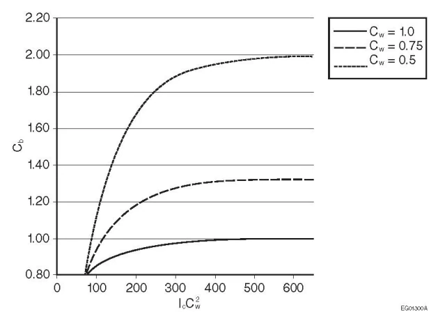
A-4.1.6.3.(2) Full and Partial Loading Under Snow Loads. Copy linkAdd bookmark
Information on full and partial snow loading on roofs can be found in the Commentary entitled “Snow Loads” in the “Structural Commentaries (User's Guide – NBC 2020: Part 4 of Division B)”.
A-4.1.6.4.(1) Rain Loads. Copy linkAdd bookmark
Information on rain loads can be found in the Commentary entitled “Rain Loads” in the “Structural Commentaries (User's Guide – NBC 2020: Part 4 of Division B)”.
A-4.1.6.4.(3) Flow Control Drains. Copy linkAdd bookmark
Part 7 contains requirements regarding the use of flow control roof drains. The designer must ensure that the building complies with both Part 4 and Part 7.
A-4.1.6.7.(1) Roof Projections. Copy linkAdd bookmark
Elevator, air-conditioning and fan housings, small penthouses and wide chimneys are examples of roof projections.
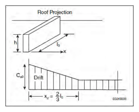
A-4.1.6.7.(2) Values of Ca for Small Roof Projections. Copy linkAdd bookmark
Calculating Ca in accordance with Article 4.1.6.5. rather than Sentence 4.1.6.7.(1) results in lower values for small projections.
A-4.1.6.9. Load Cases for Gable Roofs. Copy linkAdd bookmark
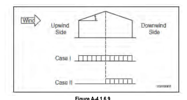
| Load Case | Roof Slope, α | Factors | |||
|---|---|---|---|---|---|
| Cw | Cs(1) | Ca | |||
| Upwind Side | Downwind Side | ||||
| I | 0° ≤ α ≤ 90° | (2) | f(α) | 1.0 | 1.0 |
| II(3) | 15° < α ≤ 20° | 1.0 | f(α) | 0.0 | 0.25 + α/20 |
| 20° < α ≤ 90° | 1.0 | f(α) | 0.0 | 1.25 | |
Notes to Table A-4.1.6.9.:
A-4.1.6.16. Roofs with Solar Panels. Copy linkAdd bookmark
Information on the design of roofs with solar panels can be found in the Commentary entitled “Snow Loads” in the “Structural Commentaries (User's Guide – NBC 2020: Part 4 of Division B)”.
A-4.1.6.16.(3) Snow Obstructed from Sliding by Solar Panels. Copy linkAdd bookmark
Figure A-4.1.6.16.(3) shows the areas on sloped roofs with solar panels where snow is considered to be obstructed from sliding by the solar panels and the slope factor, Cs, must be taken as 1.0.
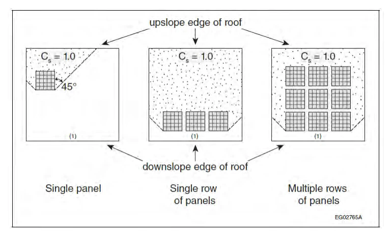
Notes to Figure A-4.1.6.16.(3):
A-4.1.6.16.(4)(b) Snow Loads for a Sloped Roof with Parallel Flush Solar Panels Where wg ≥ wp. Copy linkAdd bookmark
Figure A-4.1.6.16.(4)(b) shows the snow loads for a sloped roof with Parallel Flush solar panels where the gap width, wg, between the panels is greater than or equal to the panel width, wp.
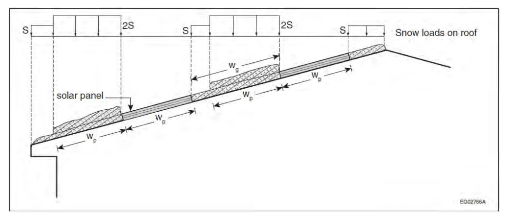
A-4.1.6.16.(4)(c) Snow Loads for a Sloped Roof with Parallel Flush Solar Panels Where wg < wp. Copy linkAdd bookmark
Figure A-4.1.6.16.(4)(c) shows the snow loads for a sloped roof with Parallel Flush solar panels where the gap width, wg, between the panels is less than the panel width, wp.
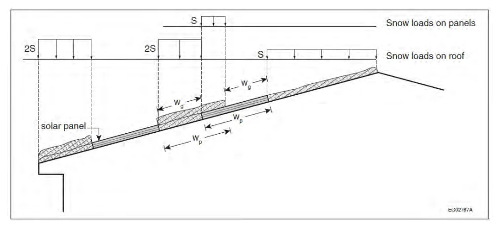
A-4.1.6.16.(5)(a) Snow Loads for a Flat Roof with Parallel Raised Solar Panels. Copy linkAdd bookmark
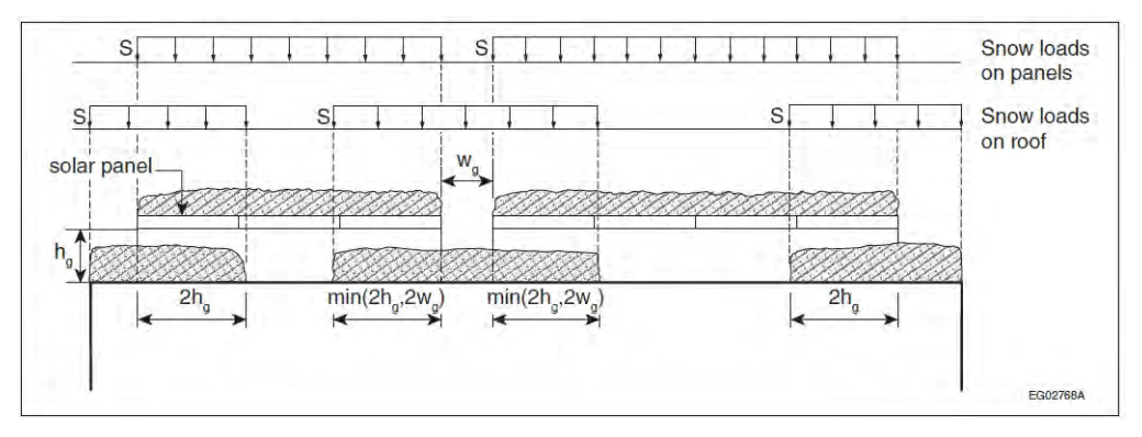
A-4.1.6.16.(5)(b) Snow Loads for a Sloped Roof with Parallel Raised Solar Panels. Copy linkAdd bookmark

A-4.1.6.16.(6) Snow Loads for a Flat Roof with Tilted Solar Panels. Copy linkAdd bookmark
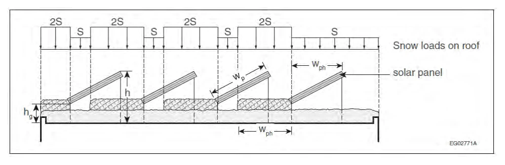
A-4.1.6.16.(6)(c) Variation of Ca with hg − CbCwSs/γ. Copy linkAdd bookmark
Figure A-4.1.6.16.(6)(c) shows the variation of the accumulation factor, Ca, with the height of the lowest edge of the panels above the surface of the uniform snow load, hg − CbCwSs/γ, for a flat roof with Tilted solar panels.
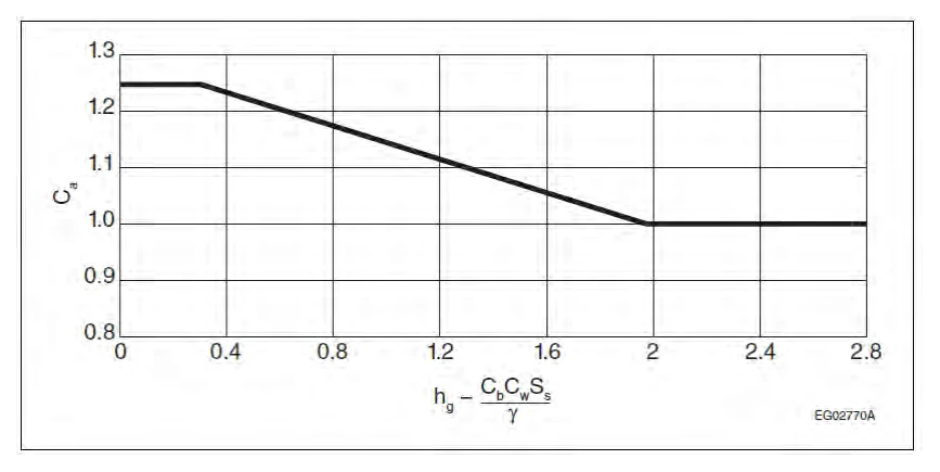
A-4.1.7.1.(6) Computational Fluid Dynamics (CFD). Copy linkAdd bookmark
It is not currently possible to verify the reliability and accuracy of CFD and no standards address it; as such, this method is not permitted to be used to determine specified wind loads.
A-4.1.7.2. Natural Frequency. Copy linkAdd bookmark
Information on calculating the natural frequency of a building can be found in the Commentary entitled “Wind Load and Effects” in the “Structural Commentaries (User's Guide – NBC 2020: Part 4 of Division B)”.
A-4.1.7.3.(5)(c) Procedure for Calculating Intermediate Ce. Copy linkAdd bookmark
Information on calculating intermediate values of Ce between two exposures can be found in the Commentary entitled “Wind
Load and Effects” in the “Structural Commentaries (User's Guide – NBC 2020: Part 4 of Division B)”.
A-4.1.7.3.(10) Internal Gust Factor, Cqi. Copy linkAdd bookmark
The effect of building envelope flexibility can be included in the calculation of Cgi. See the Commentary entitled “Wind
Load and Effects” in the “Structural Commentaries (User's Guide – NBC 2020: Part 4 of Division B)”.
A-4.1.7.5.(2) and (3) Pressure Coefficients for Main Structural System on Rectangular Buildings. Copy linkAdd bookmark
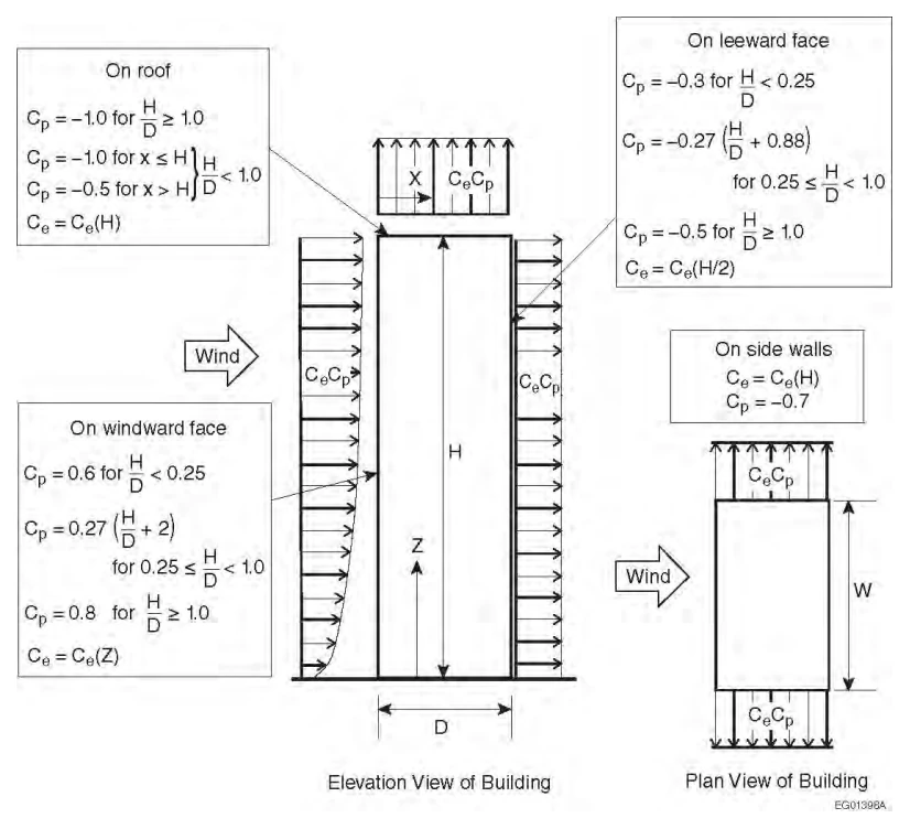
A-4.1.7.5.(4) Pressure Coefficients for Roof and Wall Claddings and Secondary Structural Supports of Cladding on Rectangular Buildings. Copy linkAdd bookmark
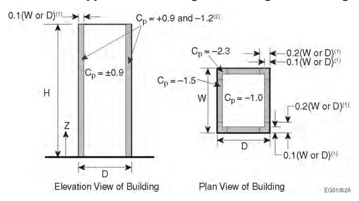
Notes to Figure A-4.1.7.5.(4):
A-4.1.7.7.(2) Cladding on Parapets. Copy linkAdd bookmark
Information on the design of cladding on parapets can be found in the Commentary entitled “Wind Load and Effects” in the “Structural Commentaries (User's Guide – NBC 2020: Part 4 of Division B)”.
A-4.1.7.8.(2) and (3) Exposure Factor for Dynamic Procedure. Copy linkAdd bookmark
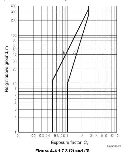
A-4.1.7.8.(4) Peak Factor, Size Reduction Factor and Gust Energy Ratio. Copy linkAdd bookmark
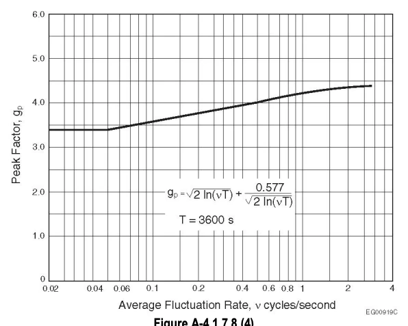
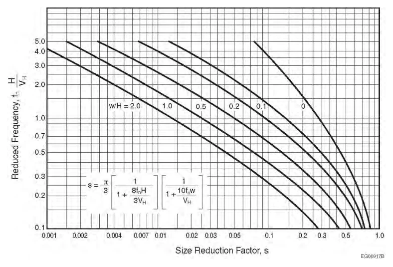
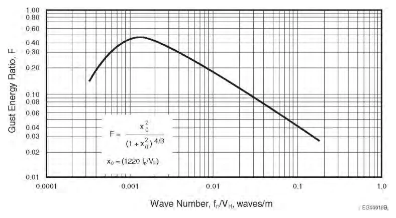
A-4.1.7.9.(1) Full and Partial Wind Loading. Copy linkAdd bookmark
Information on full and partial loading under wind loads can be found in the Commentary entitled “Wind Load and Effects” in the “Structural Commentaries (User's Guide – NBC 2020: Part 4 of Division B)”.
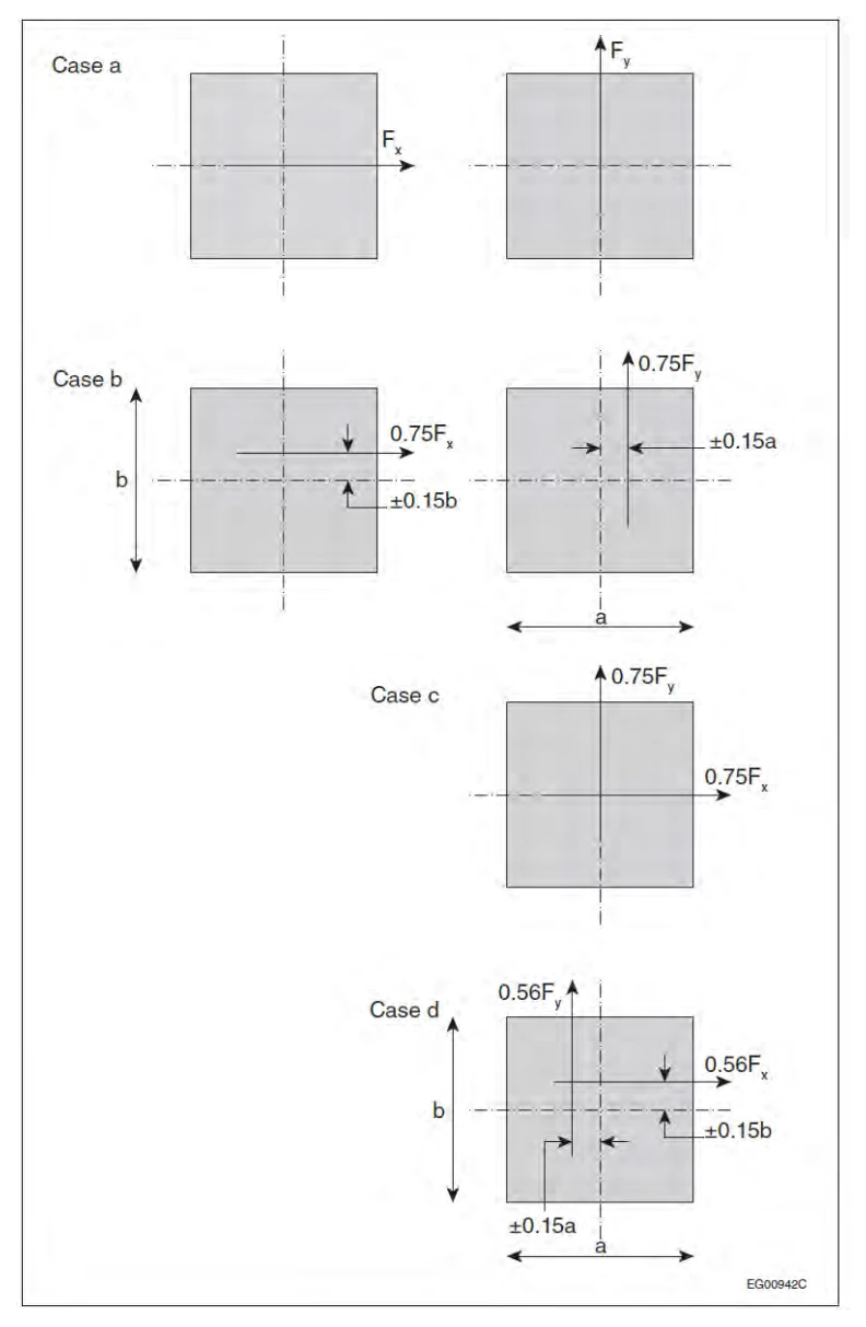
A-4.1.7.11. Exterior Ornamentations, Equipment and Appendages. Copy linkAdd bookmark
Appendages may increase the overall forces in the design of the building structure and need to be accounted for.
A-4.1.7.12. Attached Canopies on Low Buildings (H ≤ 20 m). Copy linkAdd bookmark
An attached canopy is different from an overhang, which is an extension of the roof surface.
Figure 4.1.7.12.-A, which provides the gust pressure coefficients on the upper and lower surfaces of the canopy, is used to design the cladding for the canopy and the associated fasteners. Figure 4.1.7.12.-B, which provides the net gust pressure coefficients on the canopy, is used to design the structure of the canopy (e.g., joists, posts, building fasteners).
In addition to the external wind pressure addressed in Article 4.1.7.12., the internal pressure addressed in Table 4.1.7.7. should also be considered, where applicable to the canopy.
A-4.1.7.13. Roof-Mounted Solar Panels on Buildings of Any Height. Copy linkAdd bookmark
Article 4.1.7.13. provides procedures for calculating the wind loads on roof-mounted arrays of solar panels that satisfy particular geometrical requirements.
The area of the roof that is covered by a solar array does not need to be designed for the simultaneous application of the solar array wind loads and the roof wind loads. However, the cumulative load effect of all solar panels does need to be accounted for in accordance with Article 4.1.7.11. Furthermore, the roof needs to be designed for the case where the solar array has been removed.
Solar arrays that are mechanically fastened to the underlying roof structure can modify the load distribution on the roof. The loads from such arrays must be applied to the structural components of the roof as concentrated loads at the points of attachment.
The calculations in Article 4.1.7.13. assume that the solar panels and their mounting system are rigid. Therefore, there is no allowance for wind-induced vibration of these components. However, if the panels and their mounting system have a natural frequency less than about 10 Hz, it is possible that loads will be magnified as a result of wind-induced vibration. In such cases, it is recommended that expert opinion be sought and that the dynamic effects be investigated in more detail.
Figure A-4.1.7.13. shows an example of a roof-mounted solar array with exposed and unexposed panels. For the purpose of determining the edge factor, E, to be applied in the calculations of Article 4.1.7.13., a panel is defined as exposed if it is located within a distance of 1.5 times the panel chord length, Lp, from an exposed edge of the array. An exposed edge of the array is considered to occur where the horizontal distance, d1, from the panel edge to the roof edge (ignoring any rooftop equipment) is greater than 0.5h, h being the reference height of the roof, and greater than max(4h2, 1.2 m), h2 being the height of the panel's highest point above the roof surface. An exposed edge is also considered to occur where the horizontal distance, d2, from the panel edge to the nearest edge in the next panel row (or across a gap in the same panel row) is greater than max(4h2, 1.2 m).
A sample calculation of net design wind pressure for roof-mounted solar panels is provided in the Commentary entitled Wind Load and Effects in the “Structural Commentaries (User's Guide – NBC 2020: Part 4 of Division B)”.
The installation of solar arrays on a roof can significantly affect the distribution of snow loads on the roof. Designers should be aware that the accumulation of snow and ice around solar panels can influence the calculations described in Article 4.1.7.13. For example, accumulated snow may obstruct the ventilation areas between the roof and the underside of the panels, thereby increasing wind loads on the panels. For the design of the anchorage of a solar array to the roof and of the array itself, the pressure equalization factor, γa, in Sentence 4.1.7.13.(2) should be taken as 1.0, unless it can be shown that the accumulation of snow and ice will not obstruct the gaps between the panels in the array.
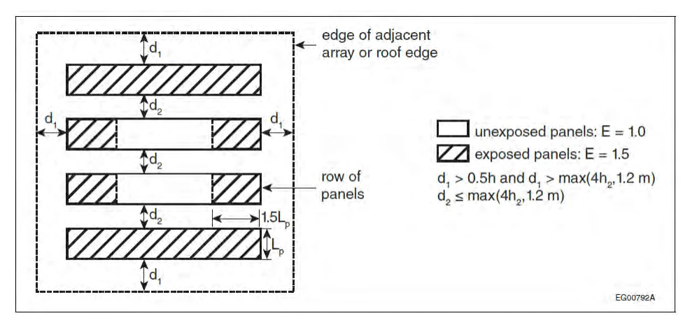
A-4.1.8.2.(1) Notation. Copy linkAdd bookmark
Definition of exCopy linkAdd bookmark
Information on the calculation of torsional moments can be found in the Commentary entitled “Design for Seismic Effects” in the “Structural Commentaries (User's Guide – NBC 2020: Part 4 of Division B)”.
Definition of WCopy linkAdd bookmark
Information on the definition of dead load, W, can be found in the Commentary entitled “Design for Seismic Effects” in the “Structural Commentaries (User's Guide – NBC 2020: Part 4 of Division B)”.
A-4.1.8.3.(4) General Design of the SFRS. Copy linkAdd bookmark
Information on the general design requirements for the SFRS can be found in the Commentary entitled “Design for Seismic Effects” in the “Structural Commentaries (User's Guide – NBC 2020: Part 4 of Division B)”.
A-4.1.8.3.(6) General Design of Stiff Elements. Copy linkAdd bookmark
Information on the general design requirements for stiff elements can be found in the Commentary entitled “Design for Seismic Effects” in the “Structural Commentaries (User's Guide – NBC 2020: Part 4 of Division B)”.
A-4.1.8.3.(7)(b) and (c) Stiffness Imparted to the Structure from Elements Not Part of the SFRS. Copy linkAdd bookmark
Information on stiffness imparted to the structure from elements not part of the SFRS can be found in the Commentary entitled “Design for Seismic Effects” in the “Structural Commentaries (User's Guide – NBC 2020: Part 4 of Division B)”.
A-4.1.8.3.(8) Structural Modelling. Copy linkAdd bookmark
Information on structural modelling can be found in the Commentary entitled “Design for Seismic Effects” in the “Structural Commentaries (User's Guide – NBC 2020: Part 4 of Division B)”.
A-4.1.8.4.(2) and (3) Site Designation. Copy linkAdd bookmark
It is preferable to determine the site designation as XV on the basis of the average shear wave velocity, V̄s30, calculated from in situ measurements of shear wave velocity. This site designation will typically result in a lower seismic demand than a site designation XS determined using the energy-corrected average standard penetration resistance, N̄60, or the average undrained shear strength, su.
Further information on site designation can be found in the Commentary entitled “Design for Seismic Effects” in the “Structural Commentaries (User's Guide – NBC 2020: Part 4 of Division B)”.
A-4.1.8.4.(3) Site Class. Copy linkAdd bookmark
The V̄s30 ranges in Table 4.1.8.4.-B are retained from the 2012 Building Code. Where required for the application of a standard referenced in Subsection 4.1.8., the Site Class for a particular site designation Xv can be determined from Table 4.1.8.4.-B on the basis of the value of V̄s30. Further information on Site Class can be found in the Commentary entitled “Design for Seismic Effects” in the “Structural Commentaries (User's Guide – NBC 2020: Part 4 of Division B)”.
A-4.1.8.4.(6) Log–Log Interpolation. Copy linkAdd bookmark
The value of S(T) for Ti < T < Tj can be determined using log–log interpolation as follows:

where log = logarithm to base 10.
A-4.1.8.4.(3) and Table 4.1.8.4.A. Site Class. Copy linkAdd bookmark
Information on Site Class can be found in the Commentary entitled “Design for Seismic Effects” in the “Structural Commentaries (User's Guide – NBC 2020: Part 4 of Division B)”.
A-Table 4.1.8.5.A. Serviceability Limit States for Earthquake. Copy linkAdd bookmark
Information on serviceability limit states for earthquake can be found in the Commentary entitled “Design for Seismic Effects” in the “Structural Commentaries (User's Guide – NBC 2020: Part 4 of Division B)”.).
A-Table 4.1.8.6. Structural Irregularities. Copy linkAdd bookmark
Information on structural irregularities can be found in the Commentary entitled “Design for Seismic Effects” in the “Structural Commentaries (User's Guide – NBC 2020: Part 4 of Division B)”.
Gravity-Induced Lateral Demand – Type 9 IrregularityCopy linkAdd bookmark
Uncoupled concrete and masonry shear walls where a large fraction of the overturning resistance is provided by axial compression, rather than through yielding of the longitudinal reinforcement, are less susceptible to amplified displacements due to gravity-induced lateral demands because the axial loads have a self-centering effect on the shear walls. Walls that are stronger than the foundation and other systems such as coupled walls, braced frames and moment frames are more susceptible to amplified displacements due to gravity-induced lateral demands. A lower limit on α is thus specified for such systems. Further information on the impacts of gravity-induced lateral demands on the seismic response of buildings can be found in the Commentary entitled “Design for Seismic Effects” in the “Structural Commentaries (User's Guide – NBC 2020: Part 4 of Division B)”.
A-4.1.8.7.(1) Dynamic Analysis Procedures. Copy linkAdd bookmark
Information on dynamic analysis procedures can be found in the Commentary entitled “Design for Seismic Effects” in the “Structural Commentaries (User's Guide – NBC 2020: Part 4 of Division B)”.
A-Table 4.1.8.9. Industrial-Type Steel Structures. Copy linkAdd bookmark
Guidance on the height limits, system restrictions and additional analysis and design requirements for steel SFRSs in industrial-type structures, intended essentially to support equipment, tanks or an industrial process, can be found in Annex M “Seismic Design of Industrial Steel Structures” of CSA S16, “Design of Steel Structures”.
A-4.1.8.9.(4) Vertical Variations in RdRo. Copy linkAdd bookmark
Information on vertical variations in RdRo can be found in the Commentary entitled “Design for Seismic Effects” in the “Structural Commentaries (User's Guide – NBC 2020: Part 4 of Division B)”.
A-4.1.8.9.(5) RdRo and Equivalent Systems. Copy linkAdd bookmark
Information on the RdRo, of equivalent systems can be found in the Commentary entitled “Design for Seismic Effects” in the “Structural Commentaries (User's Guide – NBC 2020: Part 4 of Division B)”.
A-4.1.8.10.(5) and (6) Mid-Rise Timber SFRS. Copy linkAdd bookmark
Information on structural irregularities in mid-rise wood construction and on how to determine the number of storeys for application in Sentence 4.1.8.10.(5) can be found in the Commentary entitled “Design for Seismic Effects” in the “Structural Commentaries (User's Guide – NBC 2020: Part 4 of Division B)”.
A-4.1.8.10.(7) Gravity-Induced Lateral Demand – Type 9 Irregularity. Copy linkAdd bookmark
Structural systems that include components such as inclined columns or horizontal floor cantilevers can induce lateral force demands on the SFRS under gravity loads. Buildings with such gravity-induced lateral demands on the SFRS are more likely to experience severe damage during strong ground shaking due to their tendency to drift only in one direction, leading to large residual displacements or instability. To determine if a building is susceptible to amplification of displacements due to gravity-induced lateral demands, the lateral resistance of the yielding mechanism to resist earthquake forces alone, Qy, must be compared with the gravity-induced lateral demand, QG, at the same location. The force component selected for this comparison depends on the yielding mechanism for the SFRS. For example, for a coupled wall, the overturning moment resistance at the level of the expected plastic hinges should be compared with overturning moment demand (at the same level) due to gravity loads alone; whereas for a steel braced-frame, the storey shear at the critical level of the yielding system should be compared with the storey shear demand (at the same level) due to the gravity loads alone. If the gravity-induced lateral demands exceed the limits prescribed in Sentence 4.1.8.10.(7), amplifications in seismic displacements due to gravity-induced lateral demands can only be identified through nonlinear dynamic analyses using models which adequately represent the hysteretic behaviour of the SFRS. Further information on the impacts of gravity-induced lateral demands on the seismic response of buildings can be found in the Commentary entitled “Design for Seismic Effects” in the “Structural Commentaries (User's Guide – NBC 2020: Part 4 of Division B)”.
A-4.1.8.10.(9) Gravity-Induced Lateral Demand – Non-Linear Dynamic Analysis. Copy linkAdd bookmark
Information on non-linear dynamic analysis, including ground motion time histories, target response spectra and acceptance criteria, can be found in the Commentary entitled “Design for Seismic Effects” in the “Structural Commentaries (User's Guide – NBC 2020: Part 4 of Division B)”.
A-4.1.8.10.(10)(a) Sloped Column Irregularity. Copy linkAdd bookmark
The presence of inclined vertical members in a building lead to a coupling of its horizontal and vertical vibrational modes. As a result of this coupling, horizontal accelerations of the building cause vertical accelerations of the mass supported by the inclined vertical members. Vertical ground motions cause additional vertical accelerations of the mass.
The additional earthquake forces resulting from both the coupling of horizontal and vertical vibrational modes and the vertical ground motions can be determined using the Dynamic Analysis Procedure described in Article 4.1.8.12. with RdRo = 1.0. The structural model used in the analysis must account for the vertical accelerations of all mass supported by inclined vertical members and must include the SFRS, the inclined vertical members, and all structural framing elements that transfer inertial forces generated by the vertical accelerations of the mass supported by the inclined vertical members.
The additional earthquake forces are sensitive to the degree of coupling between the vertical and horizontal vibrational modes of the building. Thus, to determine the maximum additional earthquake forces for design, the range of possible stiffness values for all structural members must be considered.
Further information on the analysis of structures with a sloped column irregularity, including a simple procedure for scaling the analysis results to avoid having to perform multiple analyses with a range of stiffness values and vertical ground motions, can be found in the Commentary entitled “Design for Seismic Effects” in the “Structural Commentaries (User's Guide – NBC 2020: Part 4 of Division B)”.
A-4.1.8.11.(3) Determination of the Fundamental Period, Ta. Copy linkAdd bookmark
Information on the determination of the fundamental period, Ta, can be found in the Commentary entitled “Design for
Seismic Effects” in the “Structural Commentaries (User's Guide – NBC 2020: Part 4 of Division B)”.
A-4.1.8.12.(1)(a) Linear Dynamic Analysis. Copy linkAdd bookmark
Information on Linear Dynamic Analysis can be found in the Commentary entitled “Design for Seismic Effects” in the “Structural Commentaries (User's Guide – NBC 2020: Part 4 of Division B)”.
A-4.1.8.12.(1)(b) Nonlinear Dynamic Analysis. Copy linkAdd bookmark
Information on Nonlinear Dynamic Analysis can be found in the Commentary entitled “Design for Seismic Effects” in the “Structural Commentaries (User's Guide – NBC 2020: Part 4 of Division B)”.
A-4.1.8.12.(3) Ground Motion Histories. Copy linkAdd bookmark
Information on ground motion histories can be found in the Commentary entitled “Design for Seismic Effects” in “Structural Commentaries (User's Guide – NBC 2020: Part 4 of Division B)”.
A-4.1.8.12.(4)(a) Accidental Torsional Moments. Copy linkAdd bookmark
Information on accidental torsional moments can be found in the Commentary entitled “Design for Seismic Effects” in the “Structural Commentaries (User's Guide – NBC 2020: Part 4 of Division B)”.
A-4.1.8.13.(4) Deflections and Sway Effects. Copy linkAdd bookmark
Information on deflections and sway effects can be found in the Commentary entitled “Design for Seismic Effects” in the “Structural Commentaries (User's Guide – NBC 2020: Part 4 of Division B)”.
A-4.1.8.15.(1) Diaphragms and their Connections. Copy linkAdd bookmark
Information on diaphragms and their connections can be found in the Commentary entitled “Design for Seismic Effects” in the “Structural Commentaries (User's Guide – NBC 2020: Part 4 of Division B)”.
A-4.1.8.15.(3) Ductile Diaphragms Copy linkAdd bookmark
Information on the design of struts, collectors, chords and connections for ductile diaphragms can be found in the Commentary entitled “Design for Seismic Effects” in the “Structural Commentaries (User's Guide – NBC 2020: Part 4 of Division B)”.
A-4.1.8.15.(4) Influence of Dynamic Diaphragm In-Plane Response. Copy linkAdd bookmark
Clause 4.1.8.15.(4)(a)Copy linkAdd bookmark
In lieu of carrying out a special study as stated in Subclause 4.1.8.15.(4)(a)(iii), the anticipated total deformation demand on the vertical elements of the SFRS, including inelastic deformations, may be taken as equal to RoRd(ΔB + ΔD) - RoΔD, i.e., the difference between the total storey drift including inelastic deformation effects and diaphragm deformations,
RoRd(ΔB + ΔD), and the diaphragm deformation under Ro times the seismic load, where Ro may be replaced by the actual overstrength of the SFRS vertical elements. The design engineer must verify that the SFRS vertical elements have sufficient deformation capacity to accommodate the computed deformation demand. If the vertical elements of the SFRS do not have sufficient deformation capacity, the design forces for the vertical elements of the SFRS must be magnified by Rd(1 + ΔD/ΔB)/(Rd + ΔD/ΔB). The calculation of the magnified design forces is iterative as the ΔD/ΔB ratio may change when using higher design forces for the vertical elements of the SFRS. Reducing the ΔD/ΔB ratio by increasing the stiffness of the roof diaphragm relative to that of the vertical elements of the SFRS may be considered to reduce the deformation demand on the vertical elements of the SFRS. Additional information can be found in the Commentary entitled “Design for Seismic Effects” in the “Structural Commentaries (User's Guide – NBC 2020: Part 4 of Division B)”.).
Clause 4.1.8.15.(4)(b)Copy linkAdd bookmark
The dynamic response of the diaphragm with the vertical elements of the SFRS under seismic excitation involves several modes of vibration that affect both the amplitude and distribution of in-plane shears and bending moments in the roof diaphragm. The shape of the fundamental mode of vibration resembles the deflected shape of the diaphragm/vertical SFRS elements under a distributed lateral load while higher modes involve increasing numbers of zero crossings of the deflected shapes along the length of the diaphragm, similar to the modes of a simply supported beam with distributed mass. Shears and bending moments therefore deviate from the values obtained from the equivalent static force procedure essentially due to higher mode response. Modal contributions to shears and bending moments in the diaphragms can be obtained from a Linear Dynamic Analysis. The contribution from the higher modes is generally more pronounced when the ΔD/ΔB ratio, the period in the first mode, or the ratio Sa(0.2)/Sa(2.0) is increased. It also increases when the SFRS is designed with a higher Rd factor as inelastic deformations of the vertical elements of the SFRS attenuate the first mode response. Methods to take into account the inelastic higher mode effects on in-plane diaphragm shears and moments are discussed in the Commentary entitled “Design for Seismic Effects” in the “Structural Commentaries (User's Guide – NBC 2020: Part 4 of Division B)”.).
A-4.1.8.15.(5) Discontinuities. Copy linkAdd bookmark
Information on elements supporting discontinuities can be found in the Commentary entitled “Design for Seismic Effects” in the “Structural Commentaries (User's Guide – NBC 2020: Part 4 of Division B)”.
A-4.1.8.15.(6) Vertical Variations in RdRo. Copy linkAdd bookmark
Information on elements of the SFRS below the variation in RdRo can be found in the Commentary entitled “Design for
Seismic Effects” in the “Structural Commentaries (User's Guide – NBC 2020: Part 4 of Division B)”.
A-4.1.8.15.(7) Concurrent Yielding. Copy linkAdd bookmark
Information on the effects of concurrent yielding of elements can be found in the Commentary entitled “Design for Seismic Effects” in the “Structural Commentaries (User's Guide – NBC 2020: Part 4 of Division B)”.
A-4.1.8.15.(8) Design Force in Elements. Copy linkAdd bookmark
Information on the design force in elements can be found in the Commentary entitled “Design for Seismic Effects” in the “Structural Commentaries (User's Guide – NBC 2020: Part 4 of Division B)”.
A-4.1.8.16.(1) Foundation Movement. Copy linkAdd bookmark
The bearing stress distribution in soil or rock that is used to determine the factored overturning resistance of the foundation influences the rotation of the foundation, which occurs due to the forces applied by the SFRS. Generally, all foundations will rotate on soil or rock. In particular, footings (a type of foundation unit) often undergo uplift at one end, and if the factored bearing stress at the other end is only over a short length, then the uplift and rotation of the footing can be significant. CSA A23.3, “Design of Concrete Structures”, contains design requirements for footings that rotate and uplift; see also the Commentary entitled “Design for Seismic Effects” in the “Structural Commentaries (User's Guide – NBC 2020: Part 4 of Division B)” for guidance and methods to account for foundation movement.
A-4.1.8.16.(2) Actual Lateral Load Capacity of the SFRS. Copy linkAdd bookmark
The actual lateral load capacity of the SFRS includes the effects of member overstrengths similar to those used to determine the Ro factors. The applicable CSA design standards include requirements on calculating the overstrengths and capacities, which may be based on the members’ nominal or probable resistance. The actual capacities are larger than the factored loads and factored resistances and, in many cases, can be significantly larger. Note that the foundations designed to develop the capacity of the SFRS will undergo movements and Sentence 4.1.8.16.(1) still applies.
A-4.1.8.16.(4) Overturning Resistance of the Foundation. Copy linkAdd bookmark
For the special case where the foundation is a footing, and where it and the attached SFRS are not constrained against rotation, it is permitted, with certain limitations, to size the footing to have a factored overturning resistance less than the overturning capacity of the supported SFRS. This approach results in a smaller footing, increased footing rotations, increased drifts in the structure, and increased soil stresses, all of which are over and above those associated with footings sized to have a factored overturning resistance equal to or greater than the overturning capacity of the SFRS. The footing itself must have a factored resistance capable of developing the required soil or rock reactions. An example of a footing and SFRS that are not constrained against rotation is an SFRS on a footing near the ground surface such that it can rotate freely and is attached to a gravity-load-resisting system (non-SFRS) that is laterally flexible and provides little lateral resistance. For this case, the SFRS is usually analyzed on its own and the resulting displacements are imposed on the non-SFRS elements in order to assess the effects on them. Cases where the footing and SFRS are attached to a system that has significant lateral stiffness require careful analysis and engineering judgement, or the footing can be capacity-designed.
Limiting the overturning moment on the foundation and the RdRo value provides some control on the increase in lateral displacement, drift and stress in the soil or rock. Cases that exceed these limits require special study.
For the common case where the SFRS and/or the footing are constrained in some way against rotation, the footing’s factored resistance must be equal to or greater than the capacity of the supported SFRS. An example of an SFRS constrained against freely rotating with the footing is an SFRS attached to adjacent foundation walls by below-grade diaphragms. Examples of footings constrained against free rotation are footings that use soil anchors to resist overturning, footings on piles, and raft foundations. Note that Sentence 4.1.8.16.(1) still applies.
See CSA A23.3, “Design of Concrete Structures,” and the Commentary entitled “Design for Seismic Effects” in the “Structural Commentaries (User's Guide – NBC 2020: Part 4 of Division B)”.
A-4.1.8.16.(6)(a) Interconnection of Foundation Elements. Copy linkAdd bookmark
Information on the interconnection of piles or pile caps, drilled piers, and caissons can be found in the Commentary entitled “Design for Seismic Effects” in the “Structural Commentaries (User's Guide – NBC 2020: Part 4 of Division B)”.
A-4.1.8.16.(7) Earthquake Lateral Pressures from Backfill or Natural Ground. Copy linkAdd bookmark
Information on methods of computing the seismic lateral pressures from backfill or natural ground can be found in the Commentary entitled “Design for Seismic Effects” in the “Structural Commentaries (User's Guide – NBC 2020: Part 4 of Division B)”.
A-4.1.8.16.(8)(a) Cyclic Inelastic Behaviour of Foundation Elements. Copy linkAdd bookmark
Information on the cyclic inelastic behaviour of piles or pile caps, drilled piers, and caissons can be found in the Commentary entitled “Design for Seismic Effects” in the “Structural Commentaries (User's Guide – NBC 2020: Part 4 of Division B)”.
A-4.1.8.16.(9) Alternative Foundation Ties. Copy linkAdd bookmark
Alternative methods of tying foundations together, such as a properly reinforced floor slab capable of resisting the required tension and compression forces, may be used. Passive soil pressure against buried pile caps may not be used to resist these forces.
A-4.1.8.16.(10) Liquefaction. Copy linkAdd bookmark
Information on liquefaction can be found in the Commentary entitled “Design for Seismic Effects” in the “Structural Commentaries (User's Guide – NBC 2020: Part 4 of Division B)”.
A-4.1.8.17.(1) Slope Stability. Copy linkAdd bookmark
Information on slope stability can be found in the Commentary entitled “Design for Seismic Effects” in the “Structural Commentaries (User's Guide – NBC 2020: Part 4 of Division B)”.
A-4.1.8.18. Elements of Structures, Non-Structural Components and Equipment. Copy linkAdd bookmark
Information on the requirements of Article 4.1.8.18. can be found in the Commentary entitled “Design for Seismic Effects” in the “Structural Commentaries (User's Guide – NBC 2020: Part 4 of Division B)”.
A-Table 4.1.8.18. Non-Structural Components and Equipment. Copy linkAdd bookmark
The failure or detachment of non-structural components and equipment during an earthquake can present a major threat to life safety. The design requirements presented in Article 4.1.8.18. are intended to ensure that such components and their connections to the building will retain their integrity during strong ground shaking. Guidelines for the seismic risk reduction of such components are given in CSA S832, “Seismic Risk Reduction of Operational and Functional Components (OFCs) of Buildings”.
4.1.8.18.(7)(e) Post-Installed Anchors. Copy linkAdd bookmark
Information on the cyclic tension load testing of anchors referred to in Clause 4.1.8.18.(7)(e) can be found in International Code Council Evaluation Service (ICC-ES) Evaluation Reports. Additional information can be found in the Commentary entitled Design for Seismic Effects in the “Structural Commentaries (User's Guide – NBC 2020: Part 4 of Division B)”.
A-4.1.8.18.(13) Storage Racks. Copy linkAdd bookmark
Free-standing storage racks contain materials typically loaded by forklift. Some are designed to store loaded pallets; however, in some cases, the stored material does not sit on a pallet. Information on storage racks can be found in the Commentary entitled Design for Seismic Effects in the “Structural Commentaries (User's Guide – NBC 2020: Part 4 of Division B)”.
A-4.1.8.18.(14) and (15) Glass Fallout and Failure. Copy linkAdd bookmark
Information on glass fallout and testing for glass fallout can be found in AAMA 501.6, “Recommended Dynamic Test Method For Determining The Seismic Drift Causing Glass Fallout From A Wall System”. Every surface other than inaccessible areas or areas where occupancy is prevented or access is prevented should be considered a “walking surface”. Additional information can be found in ASCE/SEI 7, “Minimum Design Loads for Buildings and Other Structures”, in FEMA P-750, “NEHRP Recommended Seismic Provisions for New Buildings and Other Structures”, and FEMA 450-1, “NEHRP Recommended Provisions for Seismic Regulations for New Buildings and Other Structures”, and related commentaries, and in the Commentary entitled “Design for Seismic Effects” in the “Structural Commentaries (User's Guide – NBC 2020: Part 4 of Division B)”.
4.1.8.18.(16) Elements of Structures, Copy linkAdd bookmark
Non-structural Components and Equipment in Structures with Supplemental Energy Dissipation. Information on the requirements of Sentence 4.1.8.18.(16) can be found in the Commentary entitled Design for Seismic Effects in the “Structural Commentaries (User's Guide – NBC 2020: Part 4 of Division B)”.
4.1.8.18.(18) Climatic Conditions. Copy linkAdd bookmark
Climatic conditions leading to wetness or frost at the interface between the supporting base of the array and the roof surface may adversely affect the resistance provided by friction due to gravity loads.
A-4.1.8.19.(2) Design Review. Copy linkAdd bookmark
It is strongly recommended that a design review of the seismically isolated structure and its isolation system be carried out by an independent team of professional engineers and geoscientists experienced in seismic analysis methods and the theory and application of seismic isolation. The design review should include, but not be limited to, the following:
- (a) site-specific spectra,
- (b) ground motion time histories,
- (c) modeling and analyses,
- (d) testing program and results, and
- (e) final design of all structural framing elements and isolation system components.
A-4.1.8.19.(3)(a) Non-Linear Dynamic Analysis. Copy linkAdd bookmark
Three-dimensional non-linear dynamic analysis is a complex process requiring special expertise. Guidance on non-linear dynamic analysis can be found in the Commentary entitled “Design for Seismic Effects” in the “Structural Commentaries (User's Guide – NBC 2020: Part 4 of Division B)”.
A-4.1.8.19.(4) and A-4.1.8.21.(5) Ground Motion Time Histories. Copy linkAdd bookmark
Ground motion time histories and the horizontal and vertical components shall be appropriately selected and scaled according to accepted practice. Further information on ground motion time histories can be found in the Commentary entitled “Design for Seismic Effects” in the “Structural Commentaries (User's Guide – NBC 2020: Part 4 of Division B)”.
A-4.1.8.21.(2) Design Review. Copy linkAdd bookmark
It is strongly recommended that a design review of the structure and the supplementary energy dissipation system be carried out by an independent team of professional engineers and geoscientists experienced in seismic analysis methods and the theory and application of supplementary energy dissipation. The design review should include, but not be limited to, the following:
- (a) ground motion time histories,
- (b) modeling and analyses,
- (c) testing program and results, and
- (d) final design of all structural framing elements and supplemental energy dissipation system components.
A-4.1.8.21.(4)(a) Non-Linear Dynamic Analysis. Copy linkAdd bookmark
Three-dimensional non-linear dynamic analysis is a complex process requiring special expertise. Guidance on non-linear dynamic analysis can be found in the Commentary entitled “Design for Seismic Effects” in the “Structural Commentaries (User's Guide – NBC 2020: Part 4 of Division B)”.
A-4.2.2.1.(1) Subsurface Investigation. Copy linkAdd bookmark
Where acceptable information on subsurface conditions already exists, the investigation may not require further physical subsurface exploration or testing.
A-4.2.4.1.(1) Innovative Designs. Copy linkAdd bookmark
It is important that innovative approaches to foundation design be carried out by a person especially qualified in the specific method applied and that the design provide a level of safety and performance at least equivalent to that provided for or implicit in the design carried out by the methods referred to in Part 4. Provision must be made for monitoring the subsequent performance of such structures so that the long-term sufficiency of the design can be evaluated.
A-4.2.4.1.(3) Ultimate Limit States for Foundations. Copy linkAdd bookmark
Information on ultimate limit states for foundations, including terminology and resistance factors, can be found in the Commentary entitled “Foundations” in the “Structural Commentaries (User's Guide – NBC 2020: Part 4 of Division B)”.
A-4.2.4.1.(5) Design of Foundations for Differential Movements. Copy linkAdd bookmark
Information on the design of foundations for differential movements can be found in the Commentary entitled “Foundations” in the “Structural Commentaries (User's Guide – NBC 2020: Part 4 of Division B)”.
A-4.2.4.4.(1) Depth of Foundations. Copy linkAdd bookmark
When adfreezing has occurred and subsequent freezing results in soil expansion beneath this area, the resulting uplift effect is sometimes referred to as frost jacking.
A heated building that is insulated to prevent heat loss through the foundation walls should be considered as an unheated structure unless the effect of the insulation is taken into account in determining the maximum depth of frost penetration.
A-4.2.5.1.(1) Excavations. Copy linkAdd bookmark
Information on excavations can be found in the Commentary entitled “Foundations” in the “Structural Commentaries (User's Guide – NBC 2020: Part 4 of Division B)”.
A-4.2.6.1.(1) Shallow Foundations. Copy linkAdd bookmark
Information on shallow foundations can be found in the Commentary entitled “Foundations” in the “Structural Commentaries (User's Guide – NBC 2020: Part 4 of Division B)”.
A-4.2.7.1.(1) Deep Foundation Units. Copy linkAdd bookmark
A deep foundation unit can be pre-manufactured or cast-in-place; it can be driven, jacked, jetted, screwed, bored or excavated; it can be of wood, concrete or steel or a combination thereof.
A-4.2.7.2.(1) Deep Foundations. Copy linkAdd bookmark
Information on deep foundations can be found in the Commentary entitled “Foundations” in the “Structural Commentaries (User's Guide – NBC 2020: Part 4 of Division B)”.
A-4.2.7.2.(2) Load Testing of Piles. Copy linkAdd bookmark
ASTM D1143, “Piles Under Static Axial Compressive Load”, defines routine load test procedures that have been extensively used.
A-4.3.3.1.(1) Precast Concrete. Copy linkAdd bookmark
CSA-A23.3, “Design of Concrete Structures”, requires precast concrete members to conform to CSA A23.4, “Precast Concrete - Materials and Construction”.
A-4.3.4.1.(1) Welded Construction. Copy linkAdd bookmark
Qualification for fabricators and erectors of welded construction is found in Clause 24.3 of CSA S16, “Design of Steel Structures”.
A-4.3.4.2.(1) Cold-Formed Stainless Steel Members. Copy linkAdd bookmark
There is currently no Canadian standard for the design of cold-formed stainless steel structural members. As an interim measure, design may be carried out using the limit states design provisions of ASCE/SEI 8, “Design of Cold Formed Stainless Steel Structural Members”, except that load factors, load combinations and load combination factors shall be in accordance with Subsection 4.1.3.
A-4.3.4.3.(1) Steel Building Systems. Copy linkAdd bookmark
A steel building system is defined in Section 3 of CAN/CSA-A660, “Certification of Manufacturers of Steel Building Systems”.
A-4.3.6.1.(1) Design Basis for Glass. Copy linkAdd bookmark
The load factors in Tables 4.1.3.2.A. and 4.1.3.2.B. must be applied to the adjusted wind load before designing in accordance with the referenced standard. Additional information is given in the Commentary entitled “Wind Load and Effects” in the “Structural Commentaries (User's Guide – NBC 2020: Part 4 of Division B)”.
A-4.4.2.1.(1) Design Basis for Storage Garages and Repair Garages. Copy linkAdd bookmark
Although the scope of CSA S413, “Parking Structures,” is limited to structural steel and reinforced concrete (including prestressed and post-tensioned), the intent of Sentence 4.4.2.1.(1) is to require any type of material used in the construction of storage garages and repair garages to conform to the performance level outlined in the standard.
See the Commentary entitled “Live Loads” in the “Structural Commentaries (User's Guide – NBC 2020: Part 4 of Division B)”.
A-5 Environmental Separation.Copy linkAdd bookmark
The requirements provided in Part 5 pertain to the separation of environmentally dissimilar spaces. Most obvious is the need to separate indoor conditioned spaces from unconditioned spaces, the outdoors or the ground. There are also cases where separation is needed between interior spaces which are intended to provide different environments. (See also Notes A-5.1.1.1.(1) and A-5.1.2.1.(1))
A-5.1.1.1.(1) Scope. Copy linkAdd bookmark
Part 5 provides explicit requirements related to the transfer of heat, air, moisture and sound in various forms. Control of the ingress of radon and other soil gases is addressed by the requirements related to air leakage.
A-5.1.2.1.(1) Application. Copy linkAdd bookmark
Subsection 1.3.3. of Division A specifies that Part 5 applies to all buildings except those within the scope of Part 2, Part 9 or the scope of the National Farm Building Code of Canada 1995. Because of their intended use, many buildings need only provide a limited degree of separation from the outdoor environment, the ground, or between interior spaces. The provisions in Part 5 are written to allow exemptions for these buildings.
Part 5 applies to building elements that separate dissimilar environments and to site conditions that may affect environmental loading on the building envelope.
The provisions address
- the design and construction, or selection, of building components, such as windows and doors,
- the design and construction of building assemblies, such as walls, floors and roofs,
- the design and construction of the interfaces between the above-mentioned elements, and
- the design or selection, and installation, of site materials, components and assemblies, such as backfill and drainage, and grading.
Part 5 applies not only to building elements that separate indoor space from outdoor space, but also to those elements that separate indoor space from the ground and that separate adjacent indoor spaces having significantly different environments.
Indoor spaces that require separation include interior conditioned spaces adjacent to indoor unconditioned spaces, and adjacent interior conditioned spaces that are intended to provide different environments. An extreme example of the last would be a wall that separates an indoor ice rink from a swimming pool.
Some building elements are exposed to exterior environmental loads but do not separate dissimilar environments. Solid guards on exterior walkways are one example. Such elements are subject to the application of Part 5.
A-5.1.4.1. Application of Structural Design to Other Building Elements. Copy linkAdd bookmark
Part 4, as currently written, applies primarily to buildings as a whole and to structural members. Requirements defining structural loads and design to accommodate or resist those loads, however, apply not only to buildings as a whole and components that are traditionally recognized as structural members, but also apply to other elements of the building that are subject to structural loading. This is addressed to some extent in Part 4 by the requirements that pertain, for example, to wind loads on cladding. A range of structural loads and effects, as defined in Subsection 4.1.2., may be imposed on non-loadbearing elements such as backing walls, roofing, interior partitions and their connections. These must generally be addressed using the same load determination and structural design procedures as used for structural members.
Responsibility for the structural design of buildings as a whole and their structural members is commonly assigned to the designer of record. The application of Part 4 reflects this, and as such, “non-structural” elements are not explicitly identified in the Part 4 provisions. Rather, the application of Part 4 to these elements is specified in cross-references from other Parts of the Code, e.g. Part 5, which recognizes the fact that the structural design of these elements is often carried out by designers other than the designer of record.
Part 4 does not generally apply to the structural design of building services, such as heating, ventilating, air-conditioning, plumbing, electrical, electronic or fire safety systems, though these may be subject to structural loads. It does, however, apply to the design of the connections of building services to address earthquake loads (see Article 4.1.8.18.).
A-5.1.4.1.(2) Materials, Components and Assemblies with Multiple Functions. Copy linkAdd bookmark
Where materials, components or assemblies are used to fulfill multiple functions, the designer may have to take into account their function with regard to structural loads, heat transfer, air leakage, vapour diffusion, and protection from precipitation, surface and ground water, and sound transmission. Materials should be selected taking into account the environmental loads to which they will be subjected, their physical and chemical characteristics, and their installation. Design and construction details should satisfy all intended functions and ensure continuity within and between assemblies, without adversely impacting adjacent materials, components or assemblies. The designer should also anticipate unintended consequences when materials that may fulfill multiple functions are used. For example, building membranes consisting of modified bitumen compounds, which are commonly used to control both water ingress and air leakage, also typically have low vapour transmission characteristics. Similarly, extruded polystyrene boards, which are used as thermal insulation, may also act as a component of an air barrier assembly, thus requiring wind loads to be considered.
An increasing number of manufactured systems are being used to serve more than one (and sometimes all) of the functions of an environmental separator: examples include pre-engineered building systems, exterior insulation finish systems, insulated metal panel systems, windows, other fenestration assemblies, and insulated precast concrete wall panels. These systems consist of combinations of pre-manufactured and/or site-built components, which are supposed to be assembled in a prescribed manner.
Ensuring compliance with one Section of Part 5 may impact compliance with other Sections of Part 5: for example, air barriers that are integral to some systems may also act as vapour barriers and impact condensation control. By extension, ensuring compliance with the requirements of Part 5 may impact compliance with other Parts of the Building Code: for example, increasing the thickness of the insulation to improve an assembly’s thermal performance may impact its compliance with Part 3 with regard to fire resistance.
Compliance with a standard listed in Section 5.9. does not ensure that a system is appropriate for the intended application. The designer should consider all relevant criteria, beyond the standard tests, when selecting an appropriate product for a project.
A-5.1.4.1.(5) Past Performance as Basis for Compliance with Respect to Structural Loads. Copy linkAdd bookmark
As discussed in Note A-5.1.4.1., a range of structural loads and effects can be imposed on materials, components and assemblies in environmental separators and assemblies exposed to the exterior. In many instances, compliance with Sentence 5.1.4.1.(1) for structural loads must be determined based on the loads and calculation methods described in Part 4 as specified in Sentence 5.1.4.1.(3) and the referenced Subsection 5.2.2., e.g. for cladding. In practice, compliance for some materials, components or assemblies of environmental separators and assemblies exposed to the exterior is determined by relying on provisions governing the use of alternative solutions (such as Clause 1.2.1.1.(l)(b) of Division A).
For some very common building elements and installations, however, there is a very large body of evidence of proven performance over a long period of time. In these cases, imposing the degree of analysis, or documentation of performance, required by Part 4 or Section 2.1. of Division C would be unnecessary and onerous. Clause 5.1.4.1.(5)(b) is intended to address these particular cases. Because these common building elements and assemblies are so widely accepted throughout the industry and the body of evidence is so substantial (though not necessarily documented in an organized fashion), detailed analysis or documentation is unnecessary.
Whether compliance of a particular material, component or assembly may be determined based on past performance depends not only on the type of material, component or assembly, but also on its intended function, the particular loads to which it will be subject and the magnitude of those loads. Because the possible number of combinations and permutations is astronomical, only guidelines can be provided as to when past performance is a reasonable basis for determining compliance.
In determining compliance based on past performance, the period of past performance considered should be a substantial number of years. For example, 30 years is often used to do life-cycle cost analysis of the viability of investments in building improvements. This period is more than long enough for most deficiencies to show up. There should be no question as to the structural adequacy of a material, component or assembly that has been successfully used in a given application for such a period.
The determination of compliance may be based on past performance only where the function of the material, component or assembly is identical to that of the materials, components or assemblies used as a reference, and where the expected loads do not exceed those imposed on the reference materials, components or assemblies. For example, the acceptance of gypsum board, and its fastening, to serve as part of the backing wall supporting cladding cannot be based on the performance of gypsum board that has served only as an interior finish.
The determination of compliance may be based on past performance only where the properties of the material, component or assembly are identical or superior to those of the materials, components or assemblies used as a reference. For example, where a component of a certain gauge of a particular metal has provided acceptable performance, the same component made of the same metal or a stronger one would be acceptable.
Compliance with respect to various loads may be determined individually. A particular material may have to be designed to Part 4 to establish acceptable resistance to wind or earthquake loads, for example, but past performance may be adequate to determine that the material and normal fastening will support the material’s dead load and will resist loads imposed by thermal and moisture-related expansion and contraction.
Past performance is a reasonable basis for determining compliance for lighter materials, components or assemblies not subject to wind load; for example, semi-rigid thermal insulation installed in wall assemblies where other materials, components or assemblies are installed to resist air pressure loads.
Past performance is an appropriate basis for determining compliance for some smaller elements that will be subject to wind loads but are continually supported or fastened behind elements that are designed for wind loads, for example, standard flashing over wall penetrations.
It should be noted that this particular approach to demonstrating compliance pertains only to the resistance or accommodation of structural loads described in Part 4. The resistance or accommodation of environmental loads, resistance to deterioration, and material compatibility must still be addressed in accordance with Part 5.
A.5.1.4.1.(6)(b) and (c) Accommodating Movement. Copy linkAdd bookmark
It is well understood that the deflection of the backing assembly in a wall can have significant effects on the performance of the cladding. For example, CSA S304, “Design of Masonry Structures”, specifies the maximum deflection criteria for backing assemblies to masonry veneer. Clauses 5.1.4.1.(6)(b) and (c) are written in very general terms in recognition of the fact that not only can the deflection of cladding affect the performance of the backing assembly, but that the excessive deflection of any element has the potential to adversely affect the performance of any adjacent element. Similarly, inter-storey drift has the potential to adversely affect the performance of components and assemblies of environmental separators. CSA O86, “Engineering Design in Wood”, specifies a method for calculating building movement due to changes in moisture content. The effects of movement should be avoided or accommodated.
A-5.1.4.2. Deterioration. Copy linkAdd bookmark
Environmental loads that must be considered include but are not limited to: sound, light and other types of radiation, temperature, moisture, air pressure, acids and alkalis.
Mechanisms of deterioration include:
- structural (impact, air pressure)
- hygrothermal (freeze-thaw, differential movement due to thermal expansion and contraction, ice lensing)
- electrochemical (oxidation, electrolytic action, galvanic action, solar deterioration)
- biochemical (biological attack, intrusion by insects and rodents).
Information on the effects of deformations in building elements can be found in the Commentary entitled “Effects of Deformations in Building Components” in the “Structural Commentaries (User's Guide – NBC 2020: Part 4 of Division B)”.
Resistance to deterioration may be determined based on rational analysis, such as hygrothermal modeling, field performance, accelerated testing, or compliance with guidelines provided by evaluation agencies recognized by the authority having jurisdiction. Designers of buildings covered in Part 5 can find design guidance in the NRC publication entitled “Guideline on
Design for Durability of Building Envelopes”, and in CSA S478, “Durability in Buildings”, which presents updated methodologies for analyzing resistance to deterioration that provide quantitative results to support informed design decisions.
It is noted that the effects of future climate change and their potential impact on the durability of buildings are not fully known and, as such, are still being researched and studied. How future climate change and the issues of climate resilience are incorporated in building design should be carefully considered within the context of existing Code provisions related to structural design, fire and life safety, etc.
It is also noted that CSA S478 contains requirements for actions beyond the scope of the Building Code, which may not be the responsibility of the designer, builder or authority having jurisdiction. These include requirements relating to quality assurance, inspection, maintenance, minimum design service lives and potential impacts of climate change, which are not addressed in the Code. The reference herein to CSA S478 is not intended to imply that the designer, builder or authority having jurisdiction adopt, apply or enforce any of these requirements.
Building components should be designed with some understanding of the length of time over which they will effectively perform their intended function. Actual service life will depend on the materials used and the environment to which they are exposed. The design should take into consideration these factors, the particular function of the component and the implications of premature failure, the ease of access for maintenance, repair or replacement, and the cost of repair or replacement.
Many buildings are designed such that access for maintenance, repair or replacement is not possible without damaging – or seriously risking damaging – other building elements. This can become a considerable deterrent to proper maintenance thus compromising the performance of the subject materials, components and assemblies, or other elements of the building. In cases where it is known or expected that maintenance, repair or replacement is likely to be required for certain elements before such time as the building undergoes a major retrofit, special consideration should be given to providing easy access to those elements. Anchorage points for maintenance personnel should be considered during the design of multi-storey buildings, including those of wood-frame construction, as adding them post-construction can be difficult.
Where the use of a building or space, or the services for a building or space, are changed significantly, an assessment of the impact of the changes on the environmental separators should be conducted to preclude premature failures that could create hazardous conditions.
A-5.2.1.1.(3) Soil Temperatures. Copy linkAdd bookmark
In theory, soil temperatures are needed to determine the conformance of a design to the requirements related to heat transfer and vapour diffusion. In practice, standard construction in a particular area may have proven to perform quite adequately and detailed calculations of soil temperature are unnecessary. (See also Sentence 5.2.1.3.(2).)
A-5.2.1.2.(1) Interior Environmental Loads. Copy linkAdd bookmark
The interior environmental conditions required depend on the intended use of the spaces in the building as defined in the building program. Spaces in different types of buildings and different spaces within a single building may impose different loads on the separators between interior and exterior spaces and between adjacent interior spaces. The separators must be designed to withstand the expected loads.
A-5.2.2.1.(2)(c) Determination of Structural Loads and Effects. Copy linkAdd bookmark
For the design of post-disaster buildings, the effects of earthquake loads on the ability of materials, components and assemblies and their interfaces to resist or accommodate environmental loads must be taken into account. For such buildings, seismic effects must be taken into account in the design for environmental separation, as these buildings are required to have an adequate degree of functionality after the seismic event to meet their intended function (see Article 4.1.8.13. for deflections and drift limits for post-disaster buildings). For all other buildings, damage to building components during seismic events is anticipated and these buildings are not intended to be functional after the event. However, for post-disaster buildings, seismic effects must be taken into account in the design for environmental separation, as these buildings are required to have an adequate degree of functionality after the design event to meet their intended function (see Article 4.1.8.13. for deflections and drift limits for post-disaster buildings).
However, it is important to note that earthquake effects must be taken into account in the seismic design of all building materials, components and assemblies and their interfaces covered by Article 4.1.8.18. to address life safety and the structural protection of buildings.
A-5.2.2.2. Resistance to Wind and Other Air Pressure Loads. Copy linkAdd bookmark
The wind load provisions apply to roofing and other materials subject to wind-uplift loads.
Note that, although Article 5.2.2.2. is specifically concerned with wind loads and directly references only two Sentences from Part 4, Sentence 5.2.2.1.(1) references all of Part 4 and would invoke Article 4.1.7.10. for example, that is concerned with air pressure loads on interior walls and partitions.
A-5.2.2.2.(4) Membrane Roofing Systems. Copy linkAdd bookmark
Wind loads for membrane roofing systems must be calculated in accordance with Part 4. The tested uplift resistance and factored load should satisfy the requirements of the Commentary entitled “Limit States Design” in the “Structural Commentaries (User's Guide – NBC 2020: Part 4 of Division B)”.
The test method described in CAN/CSA-A123.21, “Standard Test Method for the Dynamic Wind Uplift Resistance of Membrane-Roofing Systems”, applies only to membrane roofing systems whose components’ resistance to wind uplift is achieved by fasteners or adhesives. It does not apply to roofing systems that use ballasts, such as gravel or pavers, to secure the membrane against wind uplift.
In the case of membrane roofing systems in which the waterproof membrane is attached to the structural deck using mechanical fasteners, the wind-induced forces and the roofing system’s response are time- and space-dependent and, thus, dynamic in nature. Further information on the design and evaluation of such systems can be found in “A Guide for the Wind Design of Mechanically Attached Flexible Membrane Roofs”, published by NRC.
The wind uplift resistance obtained from the test method in CAN/CSA-A123.21 is limited to configurations with specific fastener or adhesive patterns. To extrapolate the test data to non-tested configurations, refer to ANSI/SPRI WD-1, "Wind Design Standard Practice for Roofing Assemblies", for a rational calculation procedure. However, in using this extrapolation procedure, wind loads should be calculated in accordance with the NBC. NRC's guide for wind design referenced above provides further guidance and examples of wind load calculations.
A-5.3. Heat Transfer. Copy linkAdd bookmark
In addressing issues related to health and safety, Section 5.3. calls up levels of thermal resistance needed to minimize condensation on or within environmental separators, and to ensure thermal conditions appropriate for the building use. Part 12 specifies levels of thermal resistance required for energy efficiency or calls up energy performance levels, which relate to levels of thermal resistance. Where Part 5 calls for levels of thermal resistance higher than those required by Part 12, the requirements of Part 5 take precedence.
A-5.3.1.1. Required Resistance to Heat Transfer. Copy linkAdd bookmark
The control of heat flow is required wherever there is an intended temperature difference across the building assembly. The use of the term “intended” is important since, whenever interior space is separated from exterior space, temperature differences will occur.
The interior of an unheated warehouse, for example, will often be at a different temperature from the exterior due to solar radiation, radiation from the building to the night sky and the time lag in temperature change due to the thermal mass of the building and its contents. If this temperature difference is not “intended,” no special consideration need be given to the control of heat flow.
If the warehouse is heated or cooled, thus making the temperature difference “intended,” some consideration would have to be given to the control of heat flow.
It should be noted, however, that in many cases, such as with adjacent interior spaces, there will be an intended temperature difference but the difference will not be great. In these cases, the provisions to control heat flow may be little or no more than would be provided by any standard interior separator. That is, materials typically used in the construction of partitions may provide the separation needed to meet the requirements of Section 5.3. without adding what are generally considered to be “insulating” materials.
A-5.3.1.2. Material and Component Properties and Condensation. Copy linkAdd bookmark
Total prevention of condensation is generally unnecessary and its achievement is rarely a certainty at design conditions. Part 5, therefore, requires that condensation be minimized. The occurrence of condensation should be sufficiently rare, or the quantities accumulated should be sufficiently small and dry rapidly enough, to avoid material deterioration and the growth of mould and fungi.
The Harmonized North American Fenestration Standard, AAMA/WDMA/CSA 101/I.S.2/A440, “NAFS – North American Fenestration Standard/Specification for Windows, Doors, and Skylights”, identifies procedures to determine the condensation resistance and thermal transmittance of windows, doors and skylights though testing for condensation resistance is presented as optional in the standard. As such, a fenestration product that meets the standard’s requirements on air leakage, water penetration, uniform load and other performance requirements may not meet the condensation resistance performance level needed for a given application.
Only the physical test procedure presented in CSA A440.2, “Fenestration Energy Performance”, can be used to establish the temperature index (I) value, which denotes condensation resistance performance evaluation criteria. It is recommended that designers specify I values for a given application to minimize the potential for condensation. Further guidance on the selection of the correct I value is provided in CSA A440.3, “User Guide to CSA A440.2-19, Fenestration Energy Performance”.
The scope of AAMA/WDMA/CSA 101/I.S.2/A440, which is referenced in Subsection 5.9.2., includes skylights and tubular daylighting devices (TDD). Where skylights and TDDs pass through unconditioned space, their wells and shafts may become the environmental separator and would therefore have to comply with the requirements of Part 5.
A-5.3.1.2.(1) Use of Thermal Insulation or Mechanical Systems for Environmental Control. Copy linkAdd bookmark
The level of thermal resistance required to avoid condensation on the warm side of an assembly or within an assembly (at the vapour barrier) and to permit the maintenance of indoor conditions appropriate for the occupancy depends on:
- the occupancy
- the exterior design air temperature
- the interior design air temperature and relative humidity
- the capacity of the heating system, and
- the means of delivering heat.
To control condensation on the interior surface of an exterior wall, for example, the interior surface must not fall below the dew point of the interior air. If, for instance, the interior air is 20°C and 35% RH, the dew point will be 4°C. If the interior air is 20°C and 55% RH, the dew point will be 11°C.
Exterior design temperatures are low in Ontario; for example, -20°C in Toronto, and -35°C in Geraldton. In these cases, maintaining temperatures inboard of the vapour barrier above the dew point requires insulation. In these cases, maintaining temperatures inboard of the vapour barrier above the dew point will require insulation or increased heat delivery to the environmental separator. Direct delivery of heat over the entire surface of the environmental separator is generally impractical. Indirect heat delivery may not be possible without raising the interior air temperatures above the comfort level. In any case, increased heat delivery would often entail excessive energy costs.
In addition to controlling condensation, interior surface temperatures must be warm enough to avoid occupant discomfort due to excessive heat loss by radiation. Depending on the occupancy of the subject spaces, this may require the installation of insulation even where it is not needed to control condensation.
A-5.3.1.3.(2) Position of Materials Providing Thermal Resistance. Copy linkAdd bookmark
For a material providing thermal resistance to be effective, it must not be short-circuited by convective airflow through or around the material. The material must therefore be either
- the component of the air barrier system providing principal resistance to air leakage, or
- installed in full and continuous contact with a continuous low air permeance component.
A-5.4.1. Air Barrier Systems. Copy linkAdd bookmark
An air barrier system is required in most buildings to control air movement through the environmental separator to minimize
- the condensation of airborne moisture within the environmental separator,
- discomfort from drafts,
- the infiltration of dust, soil gases, and other pollutants,
- interference in the performance of building services, such as HVAC and plumbing,
- the infiltration of exterior precipitation, and
- the loss of airborne heat energy.
The requirements for air barrier systems in Part 5 address all of these issues, except the loss of airborne heat energy, which is an energy performance issue and, as such, is addressed in the NECB. Failure to manage the issues addressed in Part 5 can lead to serious health or safety hazards.
The most significant issues are those with the potential to cause moisture-related material deterioration, such as rot and corrosion, which can lead to the failure of component connections. Where the environmental separator is subject to high moisture levels, mould can grow if spores and organic materials are present.
A-5.4.1.1. Locations Where an Air Barrier System Is Required. Copy linkAdd bookmark
Where the hygrothermal environments in adjacent interior spaces are sufficiently different, an air barrier system is required to control the airflow between the spaces in order to maintain the different environments. Examples of such adjacent spaces include skating arenas adjoining swimming pools, and industrial office spaces adjoining industrial production spaces.
An air barrier system is also required in building assemblies in contact with the ground to control the ingress of radon and other soil gases, such as methane.
In addition to an air barrier system, other measures may be required in certain regions of Canada to reduce the radon concentration to a level below the guideline specified by Health Canada. Further information on protection from radon ingress can be found in:
- “Radon: A Guide for Canadian Homeowners” (CMHC/HC),
- “Guide for Radon Measurements in Public Buildings (Schools, Hospitals, Care Facilities, Detention Centres)” (HC), and
- EPA 625/R-92/016, “Radon Prevention in the Design and Construction of Schools and Other Large Buildings.”
A-5.4.1.1.(3) Air Leakage Performance Classes for Air Barrier Assemblies. Copy linkAdd bookmark
The selection of a Performance Class for an air barrier assembly is intended to ensure that the air leakage performance level of the assembly is sufficient to minimize condensation and reduce the uncontrolled movement of air across the environmental separator.
The accumulation of condensation within a building assembly as a result of air leakage through the environmental separator depends on the following:
- the air leakage rate of the air barrier assembly,
- the location of the accumulation of condensation within the building assembly, and
- the drying potential of the building assembly (i.e., its ability to release moisture through vapour diffusion and surface evaporation, both inward and outward).
Critical to the rates of both drying and the accumulation of condensation is the location where moisture may occur within the building assembly. The location and amount of accumulation of condensation due to air leakage are influenced by the materials used in the building assembly and the temperatures within the assembly. The location of insulation within the building assembly is critical and can directly influence whether condensation occurs and how much moisture condensation actually accumulates.
The drying potential of the building assembly is dependent on the water vapour permeance of the various layers in the building assembly (e.g., exterior sheathing, sheathing membrane, unvented cladding, vapour barrier).
CAN/ULC-S742, “Standard for Air Barrier Assemblies – Specification,” contains requirements and test methods for air barrier assemblies used in high- and low-rise buildings. The standard classifies the air leakage performance of air barrier assemblies on the basis of air leakage rate, building height, and wind pressure loading. The approach in the standard is consistent with limit states design principles to allow for the direct incorporation of test results into the overall structural design of the building.
Unlike ASTM E2357, “Standard Test Method for Determining Air Leakage Rate of Air Barrier Assemblies”, CAN/ULC-S742 measures air leakage under two temperature conditions:
- (1) at ambient temperatures with no temperature differential across the test assembly, and
- (2) with the exterior side of the test assembly at a temperature of −20°C and the interior side at a temperature of +20°C (i.e., with a temperature differential of 40°C across the test assembly).
This difference makes the testing approach in CAN/ULC-S742 more appropriate for the climate in most regions of Canada.
CAN/ULC-S742 does not address the structural transfer of air pressure loads from air barrier assemblies to adjoining air barrier assemblies or the primary structure. Nevertheless, this transfer of loads must be addressed by the designer.
The Performance Class of an air barrier assembly is selected on the basis of the following:
- the moisture loads on the building assembly due to the hygrothermal characteristics of the air,
- the ability of the materials and components of the building assembly to absorb and distribute moisture,
- the ability of the building assembly to dissipate moisture before it can lead to harm to the occupants or damage to the materials and components of the building assembly, and
- the moisture tolerance of the materials from which the building assembly is constructed.
Air barrier assemblies with lower air leakage rates are typically necessary where the drying potential of the building assembly is low and/or the moisture sensitivity of components of the building assembly is high.
Before selecting the appropriate Performance Class, the designer should consider formal study, analysis and/or modeling to establish performance criteria for each air barrier assembly. Further guidance can be found in the NRC publication entitled “Guideline on Design for Durability of Building Envelopes”. This recommendation is particularly important for buildings with
- higher than normal operating hygrothermal characteristics, e.g., museums, swimming pools and laboratories,
- building assemblies made from materials and components with lower than normal moisture tolerances, e.g., wood and other organic materials, or
- occupancies with a low tolerance for the potential health risks associated with condensation, e.g., hospitals, long-term care facilities and laboratories.
In such cases, Performance Classes with lower air leakage rates should be selected.
A-5.4.1.1.(4) Continuity of Air Barrier Systems. Copy linkAdd bookmark
An air barrier system can only function properly if all the materials, components and assemblies intended to provide the air barrier functions are continuously connected and structurally capable of resisting applied loads. Historically, most failures of air barrier systems in buildings have been directly related to improper or insufficient connections between adjacent air barrier materials, components and assemblies.
A-5.4.1.1.(7) Locations Where an Air Barrier System Is Not Required. Copy linkAdd bookmark
In Ontario, there are few buildings intended for human occupancy where the interior space is conditioned but an air barrier system is not required. Any exemption from installing an air barrier system would depend on the level of interior conditioning provided, the ventilation level, the protection provided for the building's occupants, and the tolerance of the building's construction to the accumulation of condensation and potential precipitation ingress.
In some industrial buildings, limited conditioning (e.g., radiant heating) is provided, and ventilation levels are sufficient to reduce the relative humidity to a level at which condensation will not accumulate to an unacceptable degree. Conversely, some industrial buildings, due to the processes they contain, operate at very high temperatures and high ventilation levels. In such cases, the building envelope may be maintained at temperatures required to avoid condensation. In both of these examples, either the ventilation levels or protective means required in the work environment would protect the building's occupants from unacceptable levels of pollutants.
A-5.4.1.2.(1) Low-Sloped Membrane Roof Assemblies. Copy linkAdd bookmark
For low-sloped membrane roof assemblies, CAN/ULC-S742, “Standard for Air Barrier Assemblies – Specification”, provides pre-tested prescriptive solutions that have an air leakage rate not exceeding L/(s×m2). The air leakage rate of low-sloped membrane roof assemblies not identified in CAN/ULC-S742 should be determined in accordance with ASTM D8052 / D8052M, “Standard Test Method for Quantification of Air Leakage in Low-Sloped Membrane Roof Assemblies”.
A-5.4.1.2.(2) Air Barrier Assemblies Not Evaluated in Accordance with CAN/ULC-S742. Copy linkAdd bookmark
Air barrier assemblies that have not been evaluated in accordance with CAN/ULC-S742, “Standard for Air Barrier Assemblies – Specification”, must nevertheless provide the air leakage performance required for the selected Performance Class. Field testing may be required to verify their performance.
Field assessment of the air leakage characteristics of both the primary air barrier assemblies and the connections between adjacent air barrier assemblies can be a useful tool in establishing whether the acceptable minimum performance level is met.
Field testing of installed air barrier assemblies can be conducted in accordance with test standards such as
- ASTM E783, “Standard Test Method for Field Measurement of Air Leakage Through Installed Exterior Windows and Doors”, and
- E1186, “Standard Practices for Air Leakage Site Detection in Building Envelopes and Air Barrier Systems”.
Even though some test standards are intended for specific types of air barrier assemblies (e.g., windows and doors), the test methodology used to assess air leakage rates may be acceptable for use with other types of air barrier assemblies. However, with this approach, it is important to establish rational acceptance criteria that reflect the test methodology and the types of air barrier assemblies being tested.
Qualitative testing can be used to identify locations in air barrier assemblies where air leakage is occurring so that field repairs can be made to improve the assembly's airtightness performance. ASTM E1186 provides guidance on a number of approaches for identifying locations of air leakage, including the following:
- infrared scanning,
- smoke tracer observation,
- airflow measurement,
- sound detection,
- tracer gas detection, and
- liquid leak detection.
Each of these techniques has benefits and limitations, as described in the standard. The most suitable approach for a particular situation is selected by the testing agency on the basis of their experience in relation to the type of construction being assessed and the weather conditions at the time of testing. Regardless of the approach selected, the testing of air barrier assemblies must be properly coordinated with the construction process so that any air leaks identified can be addressed without adversely affecting progress.
A-5.4.1.2.(4) Testing of Below-Grade Air Barrier Assemblies. Copy linkAdd bookmark
To ensure that they minimize the ingress of radon and other soil gases, below-grade air barrier assemblies in contact with the ground can be tested in accordance with CAN/ULC-S742, “Standard for Air Barrier Assemblies – Specification,” using the air leakage limit for Performance Class 1 or a more stringent limit. In such air barrier assemblies, as in all air barrier assemblies, penetrations and junctions are the most likely locations for air leakage. These points of weakness must be properly detailed and constructed to minimize the ingress of soil gases.
A-5.5.1.1. Required Resistance to Vapour Diffusion. Copy linkAdd bookmark
Resistance to vapour diffusion is required to reduce the likelihood of condensation within building assemblies, and the consequent potential for material deterioration and fungal growth. Deterioration such as rot and corrosion can lead to the failure of building components and connections, and interfere with the performance of building services. Some fungi can have very serious effects on health.
In Ontario, relatively few buildings that are subject to temperature and vapour pressure differences would be constructed or operated in such a manner that the control of vapour diffusion would not need to be addressed in their design. Assemblies enclosing certain industrial spaces, as described in Appendix Note A-5.4.1.1.(7) for example, may be exempt.
For residential spaces and most other spaces that are conditioned for human occupancy, a means of vapour diffusion control is generally agreed to be necessary. The questions in those cases pertain to the degree of control needed.
The word “minimize” is used in Sentence 5.5.1.1.(1) because not all moisture accumulation in an assembly need be of concern. Incidental condensation is normal but should be sufficiently rare and in sufficiently limited quantities, and should dry rapidly enough, to avoid material deterioration and the growth of mould or fungi. The following publications address the effects of fungi on health:
- HC 2004, “Fungal Contamination in Public Buildings: Health Effects and Investigation Methods”
- “Guidelines on Assessment and Remediation of Fungi in Indoor Environments”, New York City Department of Health and Mental Hygiene) (NYCDH)
A-5.5.1.2.(1) Vapour Barrier Materials and Installation. Copy linkAdd bookmark
In the summer, many buildings are subject to conditions where the interior temperature is lower than the exterior temperature. Vapour transfer during these periods is from the exterior to the interior. In general, in Canada, the duration of these periods is sufficiently short, the driving forces are sufficiently low, and assemblies are constructed such that any accumulated moisture will dissipate before deterioration will occur.
Buildings such as freezer plants, however, may operate for much of the year at temperatures that are below the ambient exterior temperature. In these cases, the “warm” side of the assembly would be the exterior and a detailed analysis on an annual basis is required.
Steady state heat transfer and vapour diffusion calculations may be used to determine acceptable permeance levels for the vapour barrier and to identify appropriate positions for the vapour barrier within the building assembly.
A-5.6.1.1. Required Protection from Precipitation. Copy linkAdd bookmark
Windows, cast-in-place concrete walls, and metal and glass curtain wall systems are examples of components and assemblies that, when properly designed and constructed, are expected to prevent the ingress of precipitation into a building. Assemblies such as roofs and veneer walls consist of materials specifically intended to screen precipitation.
Components and assemblies separating interior conditioned space from the exterior are generally required to provide protection from the ingress of precipitation. Components and assemblies separating interior unconditioned space from the exterior may or may not be required to provide protection from the ingress of precipitation. Buildings such as stadia, parking garages and some seasonally occupied buildings, for example, may not require complete protection from the ingress of precipitation. The degree of protection will depend to a large extent on the materials selected for the building elements that will be exposed to precipitation.
The word “minimize” is used in Sentence 5.6.1.1.(1) because not all moisture ingress or accumulation in an assembly need be of concern. The penetration of wind-driven rain past the cladding may not affect the long-term performance of the assembly, provided the moisture dries out or is drained away before it initiates any deterioration of building materials. When the design service life of a material or component is longer than the design service life of the overall assembly, taking into account the expected exposure to moisture, initiating deterioration of the material should not be of concern. That is to say, provided the material or component continues to provide the necessary level of performance for its intended service life and does not adversely affect the service life of the assembly of which it is a part, the deterioration of the material or component is not an issue.
A-5.6.1.2.(1) Ice Damming. Copy linkAdd bookmark
Water leakage through sloped roofs is often due to the formation of ice dams at the eaves, which can be limited by controlling the transfer of heat to the roof through a combination of insulation and venting to dissipate heat. See Clause 5.3.1.2.(1)(d).
A-5.6.1.2.(2) Vegetative Roofing Systems. Copy linkAdd bookmark
The integrity of some assemblies installed to provide the required protection from the ingress of precipitation in vegetative roofing systems can be compromised due to an inadequate resistance to the penetration of plant roots and rhizomes. Additional information on vegetative roofing systems and the performance of protective materials can be found in the German Landscape Research, Development and Construction Society’s (FLL) “Guideline for the Planning, Execution and Upkeep of Green-Roof Sites” and in the National Roofing Contractors Association’s Vegetative Roof Systems Manual.
A-5.6.2.1. Sealing and Drainage. Copy linkAdd bookmark
A number of different design solutions can provide an environmental separator with the minimum performance level necessary to effectively control environmental and structural loads and their effects. An appropriate solution is selected on the basis of the applied load characteristics, the performance achieved by the solution, and its durability over the design service life. It is incumbent on the designer to balance the performance of a particular design solution against the required performance level, the risk of failure, and the consequences of failure for the building and its users.
Article 5.6.2.1. recognizes that acceptable solutions can use various strategies and single or multiple elements within the design to control precipitation. However, as indicated by research and the documentation of failures, some of these solutions are more effective than others.
One solution—a face-sealed assembly—relies on a continuous watertight surface on the outside of a building to control all precipitation over the life of the building; there is no redundancy in this design. The watertight surface can be difficult to both design and construct, and its long-term durability depends on proper preventive maintenance over its service life. This solution has a well-documented history of unsatisfactory performance in most regions of Canada.
A solution with redundancy in its design provides more effective and reliable resistance to water penetration. For example, in a rainscreen assembly, multiple water-resistive layers are combined with means to drain any water that has penetrated the outer layer and means to redirect this water to the exterior before it can affect moisture-sensitive materials within the assembly. Another solution—a mass wall assembly—accumulates and stores moisture, which is re-released to the exterior when conditions allow. Depending on the solution selected, means to facilitate the drying of materials may be incorporated in the assembly.
In selecting an acceptable solution for precipitation control, it is important to consider the structural and environmental loads that are referenced in Subsection 5.1.4. The resistance provided by the design solution must exceed these loads and their effects. The greater the intensity of the load, the higher the performance level required to provide the necessary resistance and an acceptable level of risk. Design considerations that should be addressed include the following:
- intended building use(s),
- building exposure during service life (height, orientation and surrounding terrain),
- building exposure during construction,
- current and future local climate characteristics affecting wetting and drying, including
- wind loads,
- precipitation loads (including wind-driven precipitation loads),
- relative humidity,
- temperature variations, and
- solar exposure,
- imposed load intensity, both in isolation and in combination (type, number, magnitude, frequency and duration),
- material types and moisture tolerances,
- resistance to the mechanisms of deterioration,
- effects of deformations, displacements and deflections of the building structure, and of materials, components and assemblies,
- constructability of materials, components and assemblies,
- expected construction tolerances,
- level of maintenance required to maintain resistance to loads and deterioration,
- intended service life of materials, components and assemblies, and
- reliability of materials, components and assemblies.
All the materials in an environmental separator must be able to resist the mechanisms of deterioration that are expected to occur over the design service life of the separator. For example, with respect to deterioration caused by moisture, a material used in a design must not be exposed to moisture in sufficient quantity and/or for sufficient length of time to reduce its ability to perform its required function(s) to a level below the required performance level. This concern is particularly important for materials that are known to be susceptible to moisture deterioration.
An environmental separator must also be designed to be suitably resistant to failure caused by
- uncertainty or variation in load intensity,
- uncertainty in the effects of loads on materials, components and assemblies,
- uncertainty in the predicted service lives of materials, components and assemblies, and
- construction deficiencies that can reasonably be anticipated.
The building structure and the environmental separator are mutually dependent in managing precipitation. The choice of materials for the building structure and the structural support/backing for the environmental separator can influence the choice of materials, components and assemblies for the environmental separator. Materials, components and assemblies with higher performance levels may be required for the environmental separator where the building structure and the structural support/backing have lower material strengths, undergo higher in-service movements (e.g., shrinkage or deflection), or have lower resistance to deterioration.
The design and construction of details at penetrations, at joints and junctions between assemblies, and at transitions between planes are of critical importance to the long-term performance and durability of the environmental separator. Designers should provide sufficient detail on drawings to illustrate how the design solution for precipitation control is to be integrated into the building.
A-5.7. Protection from Interior Sources of Water. Copy linkAdd bookmark
Protection similar to that prescribed in Section 5.7. may be required where interior assemblies are in contact with water (such as site-built showers, steam rooms, swimming pool areas) and where adjacent interior spaces need to be protected from the transfer of water through these assemblies.
A-5.7.1.2.(2) Drainage. Copy linkAdd bookmark
Water should be directed away from the building and, ultimately, to a municipal drainage system, drainage ditch, swale, or other acceptable water management means. This can be accomplished by setting the building grade higher than the surrounding grades, by sloping the grade away from the building, by installing a surface water drainage system, or by a combination of these approaches. The chosen approach should follow generally accepted guidelines, such as the Rational Method of Stormwater Design by David B. Thompson, or other design methods acceptable to the authority having jurisdiction.
A-5.7.3.3.(1)(a) Imperfections. Copy linkAdd bookmark
Examples of imperfections include shrinkage cracks, air holes, honeycombing, form-tie cone holes, and form joint ridges.
A-5.7.3.4.(1) Dampproofing. Copy linkAdd bookmark
Dampproofing refers to the application of a material or materials to an environmental separation assembly to protect it and the interior space against the transfer of moisture due to the mechanisms of water vapour transmission, capillary action and pressure differences other than hydrostatic pressure.
A dampproofed assembly should be designed such that it can provide short-term resistance to the ingress of water due to occasional hydrostatic pressure from ground water.
A-5.8. Required Protection from Noise. Copy linkAdd bookmark
Section 5.8. applies to the separation of dwelling units from other dwelling units and from spaces where noise may be generated with regard to sound transmission irrespective of Clause 5.1.2.1.(1)(b), which deals with the separation of dissimilar environments. It is understood that, at any time, there is the potential for sound levels to be quite different in adjoining dwelling units.
A-5.8.1.2. Using ASTC in Lieu of STC. Copy linkAdd bookmark
A designer may choose to use an ASTC rating of equal or higher numerical value than the required STC to show compliance where STC ratings are required.
An ASTC measurement or calculation will always yield a value equal to or lower than the STC for the same configuration, as the ASTC includes flanking transmission.
A-5.8.1.4. Methods of Calculating ASTC. Copy linkAdd bookmark
The technical concepts, terminology, and calculation procedures relating to the detailed and simplified ASTC calculation methods are discussed in detail, with numerous worked examples, in the NRC publication entitled “Guide to Calculating Airborne Sound Transmission in Buildings”. This Guide includes references to readily available sources of pertinent data.
For many common constructions, the calculations required by Article 5.8.1.4. can be performed using software tools, such as soundPATHS, which is available on NRC’s website.
The simplified calculation method may not always identify the prominent flanking paths. Furthermore, it corresponds more closely with the results of the detailed calculation method where the separating assembly and the flanking constructions are both constructed according to the same method, i.e. either both are lightweight construction (steel or wood framing) or both are heavyweight construction (masonry or concrete).
A-5.8.1.4.(4)(b) Assemblies that Behave Like Homogeneous Panels. Copy linkAdd bookmark
Examples of assemblies that behave like homogeneous panels include cast-in-place concrete, precast concrete, precast hollow-core concrete, concrete block masonry, and mass timber panels. For the purpose of calculating the ASTC rating for construction using mass timber panel walls or floor assemblies in accordance with the detailed method described in Sentence 5.8.1.4.(4), a mass timber panel behaves as a homogeneous panel, notwithstanding that it has an average structural loss factor greater than 0.03. Further information on the calculation of the ASTC rating for mass timber panel assemblies can be found in the NRC publication entitled “Guide to Calculating Airborne Sound Transmission in Buildings”.
A-5.9.1.1.(1) Selection of Materials and Components and Compliance with Referenced Standards. Copy linkAdd bookmark
Note that Sentence 5.9.1.1.(1) is drafted in such a way that the selection of materials and components is not limited to those traditionally recognized as serving particular functions or those for which a standard is identified in Table 5.9.1.1. This approach permits more flexibility than is provided by similar requirements in Part 9. As long as the selected material meets the performance requirements stated elsewhere in Part 5, the material may be used to serve the required function.
However, where the selected material or component, or its installation, falls within the scope of any of the standards listed in Table 5.9.1.1., the material, component or installation must comply with that standard. For example, if some resistance to heat transfer is required between two interior spaces and standard partition construction will provide the necessary resistance, the installation of one of the “thermal insulation” materials identified in the standard list is not required. If, on the other hand, one decides to install glass fibre insulation, the material must conform to CAN/ULC-S702.1, “Standard for Mineral Fibre Thermal Insulation for Buildings, Part 1: Material Specification”.
A-Table 5.9.1.1. Selection and Installation of Sealants. Copy linkAdd bookmark
Analysis of many sealant joint failures indicates that the majority of failures can be attributed to improper joint preparation and deficient installation of the sealant and various joint components. The following ASTM guidelines describe several aspects that should be considered when applying sealants in unprotected environments to achieve a durable application:
- ASTM C 1193, “Standard Specification for Use of Joint Sealants”,
- ASTM C 1472, “Standard Guide for Calculating Movement and Other Effects When Establishing Sealant Joint Width”.
The sealant manufacturer’s literature should always be consulted for recommended procedures and materials.
A-5.9.2.1.(3) Airtightness and Watertightness of Wired Glass Windows. Copy linkAdd bookmark
Fixed wired glass assemblies are sometimes permitted as closures in vertical fire separations. The airtightness and watertightness requirements are waived for these windows when used in such an application, in recognition of the fact that the availability of assemblies that meet both the requirements of the window standards and the requirements for fire resistance may be limited. However, control of air and water leakage should not be ignored: measures should be taken to attempt to comply with applicable requirements.
A-5.9.2.2. Manufactured Windows, Doors and Skylights. Copy linkAdd bookmark
Design ValuesCopy linkAdd bookmark
CSA A440S1, “Canadian Supplement to AAMA/WDMA/CSA 101/I.S.2/A440-17, NAFS – North American Fenestration Standard/Specification for Windows, Doors, and Skylights”, requires that the individual performance levels achieved by the product for structural resistance, water penetration resistance and air leakage resistance be reported on the product’s performance label.
Storm Doors and WindowsCopy linkAdd bookmark
Where storm doors and storm windows are not incorporated in a rated window or door assembly, they should be designed and constructed to comply with the applicable requirements of Part 5 regarding such properties as appropriate air leakage and structural loads.
Forced Entry TestCopy linkAdd bookmark
Even though the performance label on rated windows, doors and skylights does not explicitly indicate that the product has passed the forced entry resistance test, products are required to pass this test in order to be rated.
A-5.9.2.3.(1) Installation and Field Testing of Windows, Doors and Skylights. Copy linkAdd bookmark
InstallationCopy linkAdd bookmark
The installation details of windows, doors, skylights and their components must be appropriately designed and implemented for the building envelope assembly to perform acceptably overall. The proper design of the installation details provides the information necessary to integrate the structure and air, vapour and moisture barrier functions of windows, doors and skylights into the overall design of the building envelope assembly. Construction should be carried out in accordance with these details to achieve an appropriate level of long-term performance. Further guidance on installation detailing can be found in CAN/CSA-A440.4, “Window, Door, and Skylight Installation”.
Field TestingCopy linkAdd bookmark
It is recommended that the performance of installed windows, doors and skylights be field tested early in the envelope construction phase so that any discontinuities can be readily identified and corrected before construction of the building envelope assembly is completed. Additional field testing during subsequent construction phases to monitor installation consistency is also recommended. Field test procedures should be carried out in accordance with test standards such as ASTM E783, “Standard Test Method for Field Measurement of Air Leakage Through Installed Exterior Windows and Doors”, and ASTM E1105, “Standard Test Method for Field Determination of Water Penetration of Installed Exterior Windows, Skylights, Doors, and Curtain Walls, by Uniform or Cyclic Static Air Pressure Difference”. Further guidance can be found in Annex D of CAN/CSA-A440.4, “Window, Door, and Skylight Installation”, however, the performance requirements developed in AAMA/WDMA/CSA 101/I.S.2/A440, “NAFS – North American Fenestration Standard/ Specification for Windows, Doors, and Skylights”, should be used rather than the industry performance data values listed in CAN/CSA-A440.4.
A-5.9.2.4.(3) Heat Transfer Through Fire-Rated Glazed Assemblies. Copy linkAdd bookmark
Thermal bridging through fire-rated glazed assemblies should not be ignored; measures should be taken to minimize condensation consistent with the intent of Sentence 5.9.2.4.(2).
5.9.4.1.(1) Exterior Insulation Finish Systems (EIFS). Copy linkAdd bookmark
A-5.9.3. Testing Standards for Other Fenestration Assemblies. Copy linkAdd bookmark
Subsection 5.10.4. references ASTM test methods. The following AAMA standards can also be used to evaluate the performance characteristics of other fenestration assemblies:
- AAMA 501, “Test for Exterior Walls”,
- AAMA 501.1, “Water Penetration of Windows, Curtain Walls and Doors Using Dynamic Pressure”,
- AAMA 501.2, “Quality Assurance and Diagnostic Water Leakage Field Check of Installed Storefronts, Curtain Walls, and Sloped Glazing Systems”,
- AAMA 501.4, “Recommended Static Test Method for Evaluating Curtain Wall and Storefront Systems Subjected to Seismic and Wind Induced Interstory Drifts”,
- AAMA 501.5, “Thermal Cycling of Exterior Walls”, and
- AAMA 501.6, “Recommended Dynamic Test Method for Determining The Seismic Drift Causing Glass Fallout From A Wall System”.
A-5.9.3.1.(1) Terminology for Other Fenestration Assemblies. Copy linkAdd bookmark
Curtain WallCopy linkAdd bookmark
A curtain wall is considered to be a continuous wall cladding assembly (which may include fenestration and opaque portions) that is hung away from the edge of the primary floor structure. Curtain wall assemblies do not generally support vertical loads other than their own weight. Anchorage is typically provided by anchors that connect back to the floor structure. Curtain wall assemblies can be either “stick built,” meaning each main unit is assembled on-site, or a “unitized” system, meaning factory-assembled main units are installed and connected together on-site.
Window WallCopy linkAdd bookmark
A window wall is considered to be a wall cladding assembly (which may include fenestration and opaque portions) that spans from the top of a primary floor structure to the underside of the next higher primary floor structure. Window wall assemblies do not generally support vertical loads other than their own weight. Primary provision for anchorage occurs at head and sill connections with the adjoining floor structure. Window wall assemblies may include separate or integral floor edge covers.
StorefrontCopy linkAdd bookmark
A storefront is considered to be a non-residential assembly (which may include fenestration and opaque portions) consisting of one or more elements that could include doors, windows and curtain wall framing. Storefronts do not generally support vertical loads other than their own weight. Storefront profiles are typically narrow, rectilinear framing members that hold a combination of pocket glazing and applied glazing stops to securely retain the infills. Vertical framing members typically span the height of one floor or are retained within a structural punched opening.
Storefront assemblies are designed/selected to take into account the anticipated service and exposure conditions, which may be different than for other portions of the building.
Glazed Architectural StructuresCopy linkAdd bookmark
Glazed architectural structures are considered glazing assemblies that are supported in a non-traditional manner, such as corner-clamped, point-supported, linear-supported and edge-clamped glazing. Structural support systems can include, but are not limited to, tension cables, tension rods, steel and glass. Glazed architectural structures do not generally support vertical loads other than their own weight. These assemblies are designed/selected to take into account the anticipated service and exposure conditions, which may be different than those for other portions of the building.
Skylights that are not covered by AAMA/WDMA/CSA 101/I.S.2/A440, “NAFS – North American Fenestration Standard/Specification for Windows, Doors, and Skylights,” are considered glazed architectural structures.
A-5.9.3.2.(1) Structural Loads and Environmental Loads. Copy linkAdd bookmark
The applicable laboratory test method for demonstrating adequate structural performance of other fenestration assemblies is ASTM E330 / E330M, “Standard Test Method for Structural Performance of Exterior Windows, Doors, Skylights and Curtain Walls by Uniform Static Air Pressure Difference”.
A-5.9.3.3.(1) Resistance to Condensation. Copy linkAdd bookmark
Notwithstanding that other fenestration assemblies are not fully covered under the testing scope of CSA A440.2, “Fenestration Energy Performance”, the test method described therein can be used to evaluate their resistance to condensation, with technical modifications to accommodate differences in the size and configuration of the specimen. It is also common practice to use one cold cycle of AAMA 501.5, “Thermal Cycling of Exterior Walls”, to assess the potential for condensation. Both methods can be used for mock-ups in laboratory performance evaluations, however, only the test method in CSA A440.2 should be used if a Temperature Index is required. In most cases, the project specification documents establish the hygrothermal conditions (i.e., exterior temperature, interior temperature, interior relative humidity) for which the potential for condensation should be minimized. Under these conditions, the aforementioned test methods can be used to aid in the selection of the appropriate system performance to minimize the potential for interior surface condensation. In all cases, care should be taken in the construction and configuration of the specimen, as these parameters may have an impact on its thermal performance and resistance to condensation. These parameters may include, without limitation, interior wall construction and finishes, heating systems, ventilation systems, etc., to simulate the actual in-service conditions as closely as practicable.
A-5.9.3.4.(2) Air Leakage. Copy linkAdd bookmark
Air Leakage Rate and Test PressureCopy linkAdd bookmark
A lower air leakage rate and/or higher differential test pressure can be selected for specific applications of other fenestration assemblies where tight control of airflow is required to prevent interstitial condensation (e.g., in concealed spaces), improve thermal comfort (e.g., in hospitals, seniors’ residences), or prevent the migration of airborne contaminants (e.g., in food and drug research, manufacturing applications, biological laboratories). It is typical of other fenestration assemblies to be used as the sole building envelope component; where this is the case, a correspondingly higher degree of airtightness may be required.
In addition, higher test pressure differentials can be used to evaluate assemblies with low air leakage, such as non-operable or fixed fenestration systems whose air leakage rates are not easily measurable at the lower standard pressure differentials.
Standard Test MethodsCopy linkAdd bookmark
The applicable laboratory test method for determining the rate of air leakage is ASTM E 283, “Standard Test Method for Determining Rate of Air Leakage Through Exterior Windows, Curtain Walls, and Doors Under Specified Pressure Differences Across the Specimen”. If field testing for air leakage is to be conducted, the applicable test method is ASTM E 783, “Standard Test Method for Field Measurement of Air Leakage Through Installed Exterior Windows and Doors”.
A-5.9.3.4.(3) Systems Excluded from Air Leakage Requirements. Copy linkAdd bookmark
The systems listed in Sentence 5.9.3.4.(3) perform different functions than other fenestration assemblies and are therefore exempted from complying with the air leakage requirements.
A-5.9.3.5.(2) Standard Test Methods. Copy linkAdd bookmark
The applicable laboratory test method for determining the water penetration resistance of curtain walls and storefront assemblies is ASTM E331, “Standard Test Method for Water Penetration of Exterior Windows, Skylights, Doors, and Curtain Walls by Uniform Static Air Pressure Difference”. The applicable laboratory test method for window wall assemblies is either ASTM E331 or ASTM E547, “Standard Test Method for Water Penetration of Exterior Windows, Skylights, Doors, and Curtain Walls by Cyclic Static Air Pressure Difference”.
If field testing for water penetration is to be conducted, the applicable test method is ASTM E 1105, “Standard Test Method for Field Determination of Water Penetration of Installed Exterior Windows, Skylights, Doors, and Curtain Walls, by Uniform or Cyclic Static Air Pressure Difference”.
A-5.9.3.5.(3) Water Penetration. Copy linkAdd bookmark
Notwithstanding that other fenestration assemblies are not covered under the testing scope of CSA A440S1, “Canadian Supplement to AAMA/WDMA/CSA 101/I.S.2/A440-17, “NAFS – North American Fenestration Standard/Specification for Windows, Doors, and Skylights”, they must be tested at the driving rain wind pressure calculated in accordance with the procedure described therein.
A-5.9.3.5.(4) Systems Excluded from Water Penetration Requirements. Copy linkAdd bookmark
The systems listed in Sentence 5.9.3.5.(4) perform different functions than other fenestration assemblies and are therefore exempted from complying with the water penetration requirements.
A-5.9.4.1.(1) Exterior Insulation Finish Systems (EIFS). Copy linkAdd bookmark
The reference to CAN/ULC-S716.1, “Standard for Exterior Insulation and Finish Systems (EIFS) – Materials and Systems”, in Clause 5.9.4.1.(1)(b) does not preclude the use of other component materials that may also meet the intent of the Code. For example, using mineral-fibre insulation in lieu of other rigid insulation types, mechanical fastening methods for the insulation component in lieu of adhesive, or a type of water-resistive barrier other than a liquid-applied water-resistive barrier could be acceptable.
The following two companion standards facilitate the application of and conformance with CAN/ULC-S716.1:
- CAN/ULC-S716.2, “Standard for Exterior Insulation and Finish Systems (EIFS) – Installation of EIFS Components and Water Resistive Barrier”, and
- CAN/ULC-S716.3, “Standard for Exterior Insulation and Finish System (EIFS) – Design Application”.
Additional information on EIFS design and installation can be found in the EIFS Council of Canada’s “EIFS Practice Manual” and the manufacturer’s literature.
EIFS SelectionCopy linkAdd bookmark
CAN/ULC-S716.1 provides minimum performance criteria for EIFS materials and systems that are tested under specific laboratory test protocols identified in the standard. However, compliance with this standard does not ensure that a system is appropriate for all projects. When selecting an EIFS product, designers should consider all relevant criteria—not only those covered by the tests in CAN/ULC-S716.1—including, but not limited to,
- building exposure
- local climate characteristics (wind, precipitation, temperature variations, solar exposure)
- intended building use
- intended resistance to damage and deterioration
- construction tolerances
- constructability
Design and Construction of EIFS Drainage CavityCopy linkAdd bookmark
The drainage capacity and thermal performance of the EIFS assembly can be affected by the dimensions and configuration of the EIFS drainage cavity.
EIFS are installed over other building materials such as sheathing and primary structural components, which have various construction installation tolerances. Designers should take into consideration the cumulative effects of construction tolerances and sequencing when specifying the drainage method and the cavity dimensions and configuration in order to ensure adequate drainage.
Designers should also take into account the impact of air movement, which varies depending on cavity size and the extent of venting, on the EIFS’ thermal performance when reviewing the overall thermal performance of the building envelope. ASTM C 1363, “Standard Test Method for Thermal Performance of Building Materials and Envelope Assemblies by Means of a Hot Box Apparatus”, presents one method for assessing the thermal performance of assemblies.
A-6.1.1.1.(2) Repairs and Alterations. Copy linkAdd bookmark
This requirement is to ensure that minimum life safety and health requirements are maintained when the operation and/or design is modified on existing heating, ventilating or air-conditioning systems. For example, this provision would apply to such cases as
- (a) the conversion of a heating appliance from oil to gas where venting and clearance requirements differ for chimneys and
- (b) the branching of a new duct from a main supply duct in which the new duct now penetrates a fire separation.
A-6.2.1.1. Good Engineering Practice. Copy linkAdd bookmark
Building PressurizationCopy linkAdd bookmark
New buildings tend to be considerably more airtight than older ones. Consequently, these buildings may have a reduced pressurization requirement compared to the normal requirement in order to limit drafts and provide a reasonable level of comfort.
The humidification and relative pressurization of buildings and individual spaces in buildings can be significant factors in compromising the ongoing performance of the building envelope and other environmental separators.
In new construction, HVAC designers should take this issue into consideration and confer with those responsible for the design of the environmental separators so as to limit unintended effects on the environmental separators. In existing buildings, the ability of the environmental separators to resist or accommodate increases in pressure differential or moisture loading should be considered before changes are made to the HVAC system.
Legionella ControlCopy linkAdd bookmark
HVAC designers should either develop a water management plan or complete a formal risk and hazard assessment to determine what measures are required for the control of legionella. The risk and hazard assessment should include inspections of the building and its surroundings to locate potential sources of legionella and to identify equipment or systems that could promote the growth and spread of legionella. The assessment should also evaluate the risk to building occupants that is associated with any identified equipment or systems, taking into account their design, location and operating conditions.
Further information on minimizing the growth and spread of legionella can be found in the following publications:
- ANSI/ASHRAE 188, “Legionellosis: Risk Management for Building Water Systems,”
- “Developing a Water Management Program to Reduce Legionella Growth and Spread in Buildings” (U.S. Centers for Disease Control and Prevention, 2017)
- “Legionella and Legionnaires' Disease: A Policy Overview” (European Agency for Safety and Health at Work, 2011),
- “Legionella and the Prevention of Legionellosis” (World Health Organization, 2007),
- “Legionnaires' Disease: Technical Guidance: Part 1: The Control of Legionella Bacteria in Evaporative Cooling Systems, and Part 3: The Control of Legionella Bacteria in Other Risk Systems” (U.K. Health and Safety Executive, 2013), and
- “Recognition, Evaluation and Control of Legionella in Building Water Systems” (American Industrial Hygiene Association, 2015).
Radon ControlCopy linkAdd bookmark
Measures may be necessary to reduce the radon concentration to a level below the guideline specified by Health Canada.
Further information on reducing the indoor concentration of radon can be found in the following Health Canada publications:
- “Guide for Radon Measurements in Public Buildings (Schools, Hospitals, Care Facilities, Detention Centres),” and
- “Radon: A Guide for Canadian Homeowners.”
A-6.2.1.4. Structural Movement. Copy linkAdd bookmark
This Article is intended to remind designers and installers of mechanical systems of one aspect of the “good engineering practice” referred to in Article 6.2.1.1.
In determining how to accommodate structural movement, there are two important principles to bear in mind:
- The prime concern of the Code is the safety of people in and around the building, as opposed to protection of the mechanical systems and equipment.
- The nature of the accommodation will vary with the type of movement being considered, taking into account particularly how often the movement is likely to be encountered over the life of the building.
For example, a gas line supported on columns that also support a crane must be installed in such a way that the movement of the columns, which occurs many times daily, does not cause the lines to break, thus creating a hazard. Even if the gas line installation could somehow be designed to break in a non-hazardous manner, it would hardly be recognized as good engineering practice if movement that occurs so frequently could disrupt the operation of the mechanical system. On the other hand, earthquakes occur far less frequently and it would not be surprising to have a non-critical mechanical system fail as a result of an earthquake. However, even in this situation, the failure must occur in a manner that does not create a hazard to building occupants. For example, heavy mechanical equipment should be properly anchored so that it does not topple on building occupants during an earthquake. The design of the anchors should take into account accelerations consistent with the seismic data given in MMAH Supplementary Standard SB-1 for the location of the building. Part 4 provides guidance on the calculation of the loads such equipment would exert on the building structure during an earthquake; these same loads can be used in designing the anchors.
Some mechanical equipment can be an important component of post-disaster life safety systems. In these cases, the measures needed to accommodate the movements caused by an earthquake become even more critical since failure of the equipment would not be acceptable.
Clearly, complying with this requirement will, in most cases, necessitate close coordination between the mechanical designer and the structural designer.
For additional information on the types of structural movement that may be encountered, see Article 4.1.3.5., Sentence 4.1.3.3.(2) and Subsection 4.1.8.
A-6.2.1.6.(1) Installation - General. Copy linkAdd bookmark
Ducts or pipes without dampers or valves are generally not considered to constitute “equipment” and are therefore not subject to this requirement.
A-6.3.1.2.(1) Ventilation and Venting of Crawl Spaces and Attic or Roof Spaces. Copy linkAdd bookmark
The cross-reference to Part 5 pertains to unconditioned and unoccupied crawl spaces, and attic or roof spaces, which are effectively within the building envelope. That is, unconditioned and unoccupied attic or roof spaces are located between the roof deck and roofing above, and the insulation, air barrier system and vapour barrier below. Unconditioned and unoccupied crawl spaces are located between the ground cover below and the insulation, air barrier system and vapour barrier above. Venting of these spaces has implications for the performance of the building envelope rather than having direct effects on indoor conditions. The ventilation of conditioned or occupied crawl spaces and attic or roof spaces must comply with Part 6.
The requirements in Part 5 are stated in terms of loads that must be resisted rather than in terms of building elements. Thus, the Code user will not find explicit references in Part 5 to crawl spaces, or attic or roof spaces. Part 5 makes reference to the need for venting environmental separators, i.e., the dissipation of heat or moisture.
Sentence 6.3.1.2.(1) requires that crawl spaces be ventilated either by natural (above-grade only) or mechanical means. High moisture levels within the crawl space can lead to problems such as the formation of mould, lifting of flooring or long-term damage to structural components.
Crawl space ventilation cannot be expected to correct moisture-related problems caused by other factors like inadequate surface drainage from the foundation walls or improper protection against moisture from the ground. These conditions must be properly addressed so that crawl space ventilation can meet its intended objectives.
Several factors favour the use of mechanical ventilation rather than reliance on natural drafts. Local conditions, such as areas with high water tables, may dictate the need for mechanical ventilation to remove excessive moisture.
Crawl spaces should be maintained at a negative pressure relative to the conditioned area above to prevent the migration of moisture into occupied areas. This can be achieved through the use of an exhaust fan and relying on air transfer through floor penetrations, such as pipes.
A-6.3.1.3.(1) Storage Garages. Copy linkAdd bookmark
Areas where motor vehicles are parked with engine off for extended periods of time, such as car dealership showrooms, are not considered as storage garages.
A-6.3.1.3.(2) Ventilation of Storage Garages. Copy linkAdd bookmark
Storage garages are ventilated to protect occupants from exposure to carbon monoxide and other vehicular exhaust fumes. In certain cases, such as small two- or three-bay storage garages that are used for occasional vehicle storage, and where occupants are not present, carbon monoxide or nitrogen dioxide monitoring devices may be omitted if the ventilation system is interlocked with a local light switch or other controls to ensure continuous system operation whenever the area is occupied. In any event, the ventilation system capacity must be designed to limit the concentrations of carbon monoxide or nitrogen dioxide at or below the prescribed values.
A-6.3.1.5. Indoor Air Contaminants. Copy linkAdd bookmark
Contaminants of ConcernCopy linkAdd bookmark
Indoor air can contain complex mixtures of contaminants of concern such as formaldehyde, legionella, mould and emissions from building materials. While some contaminants may be knowingly introduced — as in the case of processing and manufacturing environments—others may be unintentionally released into indoor environments. “Industrial Ventilation: A Manual of Recommended Practice for Design”, published by the ACGIH, and the “Exposure Guidelines for Residential Indoor Air Quality”, published by Health Canada, are useful references on the control of contaminants in industrial workplace environments and residential settings, respectively. These and other guidelines and manuals should be interpreted while keeping in mind the settings and purposes for which they were developed compared to those to which they will be applied. Note that such documents do not necessarily consider the interactions between various contaminants.
Minimizing the Growth and Spread of Bio-ContaminantsCopy linkAdd bookmark
Bio-contaminants, such as bacteria, mould, mildew, fungi, viruses, and pollen, can thrive in or be spread by sources like drain pans, spray-water air-washers, contaminated filters, poorly maintained cooling coils, water incursion into ductwork, high humidity and stagnant water, potentially causing a wide range of adverse health effects including respiratory allergic reactions, asthma, and diseases ranging from influenza to legionellosis.
Some of the control measures are as follows:
- a) Air-handling equipment should be accessible for the maintenance of filters, cooling coils and condensate drain pans located below the cooling coils. Access doors should be large and easy to open to facilitate thorough and regular maintenance.
- b) If moisture is added to building ventilation air to maintain humidity levels in a designated range, humidifiers that inject steam or water vapour into central air-handling units or main supply ducts are normally used. Injection nozzles should not be located in air-handling unit plenums or ductwork that is insulated with internal fibrous lining. If the lining becomes wet, conditions conducive to the growth and spread of bio-contaminants will result.
- c) HVAC systems that generate condensate or introduce liquid water into the airstream in the ducts require adequate drainage of excess water and, in some cases, a means of capturing air-entrained water droplets. These measures reduce the potential for bio-contaminants, including legionella, to proliferate in stagnant water and for water droplets containing bio-contaminants to be introduced into the airstream and contaminate the indoor environment. (See also Article 6.3.2.2.)
The above only addresses built-in features of an HVAC system that can help to minimize the growth and spread of bio-contaminants. Even more important than the built-in features is a program of regular maintenance and cleaning of those portions of the system where such growth is likely to occur.
A-6.3.2.2. Stagnant Water in Drain Pans. Copy linkAdd bookmark
It is important to eliminate stagnant water as it can promote the proliferation of disease-causing micro-organisms, such as legionella.
Of particular concern is the potential for legionella bacteria in water to become airborne in water droplets or mist that can be inhaled by humans or can contaminate other water sources or systems.
A-6.3.2.5. Duct Coverings and Linings. Copy linkAdd bookmark
The Thermal Insulation Association of Canada (TIAC) “Mechanical Insulation Best Practices Guide” is a comprehensive source of information on the selection, installation and proper use of thermal insulation materials. (Note that Section 4 of this Guide is not included in the scope of this Note as it contains information on proprietary products, which are not within the mandate of the Code.)
A-6.3.2.10.(5) and (6) Exhausting to Garages. Copy linkAdd bookmark
A frequent practice in the design of ventilation systems serving buildings which have associated parking garages is to discharge exhaust air from the building to the garage in order to reduce the cost of heating the garage or reduce the length of the exhaust ducts.
However, this practice entails a certain amount of risk since, when the exhaust system is not running, stack effect may turn the exhaust outlets into intakes and exhaust fumes (including carbon monoxide) can be drawn from the garage into the building. Incorporating a backdraft damper at the exhaust outlet provides some additional protection but backdraft dampers are generally not regarded as being very reliable. Therefore, this practice is only permitted in very limited circumstances.
A-6.3.2.10.(6)(b) Air Contaminants. Copy linkAdd bookmark
For the purpose of Clause 6.3.2.10.(6)(b), washroom exhaust air is not considered to contain contaminants that would adversely affect the air quality in the storage garage.
A-6.3.2.10.(7) and (8) Exhaust Ducts Connected to Laundry-Drying Equipment. Copy linkAdd bookmark
Clothes dryers are a major cause of fires in buildings often due to a build-up of lint in the system, which then ignites or obstructs the venting or ventilation. Proper cleaning and regular maintenance of lint traps is directly proportional to the ease of access to the lint traps. It is therefore important to ensure that lint traps in multiple installations of laundry-drying equipment are installed in such a way as to allow easy access for inspection, maintenance, repair and cleaning.
A-6.3.2.10.(12)(b) Operation Diversity Factor. Copy linkAdd bookmark
The operation diversity factor has to be assessed for each specific application. Good engineering practice (see Article 6.2.1.1.) design guidelines can provide information on the subject. Figure A-6.3.2.10.(12)(b), which originates from the ASHRAE handbooks, provides an example of factors that can be used for general applications.
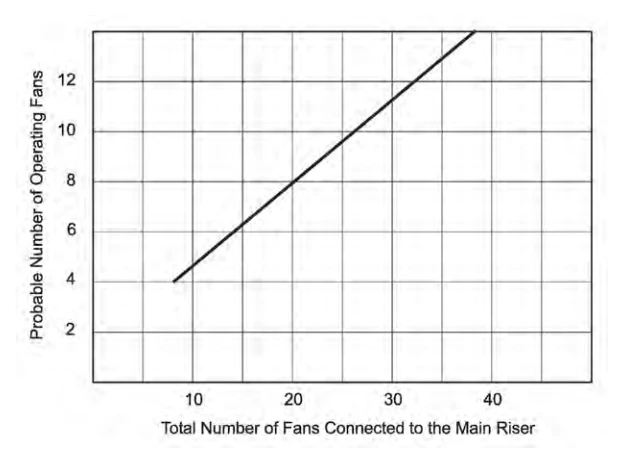
A-6.3.2.15.(5) and (6) Minimum Distances. Copy linkAdd bookmark
Ensuring adequate distance between the air discharge locations of evaporative heat rejection systems and certain outdoor spaces and building components minimizes the potential for contamination of the air of occupiable spaces. For example, if a building's ventilation air intake were located too close to an air discharge location of an evaporative heat rejection system, warm discharge air and associated drift, which could contain biological contaminants, could be introduced to the indoor environment through the air intake.
The minimum distances stated in Sentences 6.3.2.15.(5) and (6) may need to be increased where warranted by local conditions such as prevailing winds, adjacent structures, or special processes being carried out, any of which would make further analysis necessary. (See also Sentence 6.3.3.1.(2))
A-6.3.2.15.(8) and (9) Assessment of System and Make-Up Water. Copy linkAdd bookmark
The chemical characteristics of the water in the evaporative heat rejection system and of the make-up water should be assessed to select a suitable water treatment system.
A-6.3.2.16.(2) Prevention of Water Stagnation. Copy linkAdd bookmark
Common strategies to prevent water stagnation include flushing, providing an inactivity drain, and periodic activation, even with no load.
A-6.3.2.16.(6) Assessment of Make-Up Water. Copy linkAdd bookmark
The chemical characteristics of the make-up water should be assessed to ensure that any chemicals added to a system referred to in Sentence 6.3.2.16.(1) for precipitation control, disinfection or another purpose will not adversely affect the system.
A-6.3.3.1.(2) Requirement for Venting. Copy linkAdd bookmark
Sentence 6.3.3.1.(2) requires that vented products of combustion from appliances be discharged a minimum distance away from certain outdoor spaces and building components in cases where the vented products could contaminate the air of occupiable spaces. These minimum distances may need to be increased due to local conditions such as prevailing winds, adjacent structures, special processes being carried out, specific contaminants or effluent discharges, all of which would require further analysis.
“Occupiable outdoor spaces” refers to areas that could be occupied for a duration of more than fifteen minutes at any time, but does not include maintenance spaces. Occupiable outdoor spaces are located adjacent to an indoor space and are considered to be an extension of this indoor space: e.g. main entries, balconies, patios, decks, green roofs and other public assembly areas. Although sidewalks and driveways are mentioned in the provision, these areas are not considered as occupiable outdoor spaces since they are used as transport routes to and from the building, and people are not expected to remain there for extended periods of time.
The requirements of Sentence 6.3.3.1.(2) are not meant to override similar requirements found in the installation standards referenced in Article 6.2.1.5. that address identical situations.
A-6.5.1.1.(3) Temperature of Exposed Piping. Copy linkAdd bookmark
Piping carrying steam, high-temperature hot water, or another heat transfer fluid at high temperature is usually insulated to reduce heat losses as an economy measure. Above a temperature of approximately 52°C, however, a bare pipe can cause a burn to human skin coming in contact with the pipe. According to ASTM C1055, “Standard Guide for Heated System Surface Conditions that Produce Contact Burn Injuries”, skin can be in contact with a surface at a temperature of 52°C for up to 60 s without experiencing irreversible damage. If pipes above this temperature are normally out of reach of all persons other than maintenance personnel or are properly guarded, it would be expected that no insulation would be needed for public safety.
A-6.9.1.2.(1) NFPA Publications Pertaining to the Heating, Ventilating and Air-Conditioning of Spaces Containing Hazardous Gases, Dusts or Liquids. Copy linkAdd bookmark
NFPA 30, “Flammable and Combustible Liquids Code” NFPA 30A, “Code for Motor Fuel Dispensing Facilities and Repair Garages” NFPA 32, “Standard for Drycleaning Plants” NFPA 33, “Standard for Spray Application Using Flammable and Combustible Materials” NFPA 34, “Standard for Dipping, Coating and Printing Processes Using Flammable or Combustible Liquids” NFPA 35, “Standard for Manufacture of Organic Coatings” NFPA 36, “Standard for Solvent Extraction Plants” NFPA 40, “Standard for Storage and Handling of Cellulose Nitrate Film”. NFPA 51, “Standard for Design and Installation of Oxygen-Fuel Gas Systems for Welding and Cutting, and Allied Processes” NFPA 51A, “Standard for Acetylene Cylinder Charging Plants” NFPA 55, “Compressed Gases and Cryogenic Fluids Code” NFPA 61, “Standard for Prevention of Fires and Dust Explosions in Agricultural and Food Processing Facilties”
NFPA 68, “Standard for Explosion Protection by Deflagration Venting” NFPA 69, “Standard for Explosion Prevention Systems” NFPA 85, “Boiler and Combustion Systems Hazards Code” NFPA 86, “Standard for Ovens and Furnaces” NFPA 88A, “Standard for Parking Structures” NFPA 91, “Standard for Exhaust Systems for Air Conveying of Vapors, Gases, Mists and Noncombustible Particulate Solids” NFPA 96, “Standard for Ventilation Control and Fire Protection of Commercial Cooking Operations” NFPA 204, “Standard for Smoke and Heat Venting” NFPA 303, “Standard for Marinas and Boatyards” NFPA 307, “Construction and Fire Protection of Marine Terminals, Piers and Wharfs” NFPA 409, “Standard for Aircraft Hangars” NFPA 415, “Standard for Airport Terminal Buildings, Fueling, Ramp Drainage, Loading Walkways” NFPA 484, “Standard for Combustible Metals” NFPA 490, “Storage of Ammonium Nitrate” NFPA 654, “Standard for Prevention of Fire and Dust Explosions from the Manufacturing, Processing, and Handling of Combustible Particulate Solids” NFPA 655, “Standard for Prevention of Sulfur Fires and Explosions” NFPA 664, “Prevention of Fires and Explosions in Wood Processing and Woodworking Facilities” NFPA “Fire Protection Guide to Hazardous Materials”
A-6.9.3.1.(6) Carbon Monoxide Alarms. Copy linkAdd bookmark
Battery-powered carbon monoxide alarms are acceptable provided that they are mechanically fastened in place.
A-7.1.2.1.(2) Combined Building Drains. Copy linkAdd bookmark
Combined building drains may have proven acceptable on the basis of past performance in some localities and their acceptance under this Code may be warranted.
A-7.1.2.4.(1) Service Piping. Copy linkAdd bookmark
Building sewers and water service piping serving buildings that are not located within the same property may be interconnected if the owners of the properties and the municipality enter into an agreement that is registered against the title to which it applies.
A-7.1.4.1.(1) Seismic Restraints and Design. Copy linkAdd bookmark
Sentence 7.1.4.1.(1) aims to help ensure that plumbing systems will remain in place for a sufficient amount of time during an earthquake to allow for the safe evacuation of the building.
A-7.2.2.3.(1) Showers. Copy linkAdd bookmark
One method of ensuring that the floor complies with Sentence 7.2.2.3.(1) is to use a non-ferrous sheet metal or a rubber or plastic membrane and, where the protected floor area adjoins a perimeter wall, the water stop shall be turned up at least 100 mm above the waste opening.
A-7.2.2.4.(1) Concealed Overflows. Copy linkAdd bookmark
The use of concealed overflows does not preclude the use of a standing waste.
A-7.2.2.6.(1) Centre Outlet Waste Fitting. Copy linkAdd bookmark
Centre outlet waste fitting means a drain that is equipped with a flat metal strainer at the waste inlet of a tailpiece and it is commonly known as a grid drain.
A-7.2.3.1.(3) Island Sink Installation. Copy linkAdd bookmark
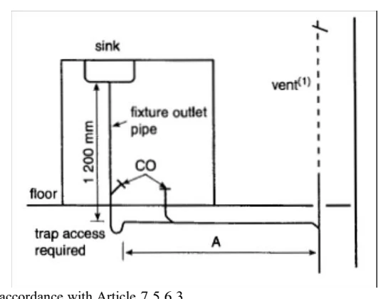
- (1) Vent to be sized in accordance with Article 7.5.6.3.
- (2) Length A depends on trap size.
A-7.2.3.2.(3) Grease Interceptors. Copy linkAdd bookmark
CSA B481.4, “Maintenance of grease interceptors”, is considered to represent good practice regarding procedures for the maintenance of grease interceptors.
A-7.2.5.2.(3) Concrete Fittings. Copy linkAdd bookmark
Concrete fittings fabricated on the site from lengths of pipe may have proven acceptable on the basis of past performances in some localities and their acceptance as an alternative solution pursuant to Section 2.1. of Division C may be warranted.
A-7.2.5.5.(1) Polyethylene Pipe Used Underground. Copy linkAdd bookmark
Joints within the high-density polyethylene pipe (HDPE) shall be heat-fused according to the manufacturer’s instructions. Joints between HDPE pipes and other materials shall be made with a suitable hubless coupling.
A-7.2.5.6.(1) Crosslinked Polyethylene Pipe and Fittings. Copy linkAdd bookmark
There are some special installation requirements for the use of crosslinked polyethylene pipe and its associated fittings. Reference should, therefore, be made to the installation information in CAN/CSA-B137.5, “Cross-Linked Polyethylene (PEX) Tubing Systems for Pressure Applications”.
A-7.2.5.9. to 7.2.5.11. Solvent Cement. Copy linkAdd bookmark
CSA B137.6, “Chlorinated polyvinylchloride (CPVC) pipe, tubing, and fittings for hot-and cold-water distribution systems,” CSA B181.1, “Acrylonitrile-butadiene-styrene (ABS) drain, waste, and vent pipe and pipe fittings,” and CSA B181.2, “Polyvinylchloride (PVC) and chlorinated polyvinylchloride (CPVC) drain, waste, and vent pipe and pipe fittings,” reference ASTM D3138, “Standard Specification for Solvent Cements for Transition Joints Between Acrylonitrile-Butadiene-Styrene (ABS) and Poly(Vinyl Chloride) (PVC) Non-Pressure Piping Components,” which specifies the colour of the solvent cement. PVC cement shall be grey, ABS cement shall be yellow, CPVC cement shall be clear and transition cement shall be white. The standard colour allows Code users to readily determine if the correct solvent cement has been used. It should be noted that a transition cement is not an all-purpose cement.
A-7.2.5.12.(1) Polyethylene/Aluminum/Polyethylene Composite Pipe and Fittings. Copy linkAdd bookmark
There are some special installation requirements for the use of polyethylene/aluminum/polyethylene composite pipe and fittings. Reference should, therefore, be made to the installation information in CAN/CSA-B137.9, “Polyethylene/ Aluminum/Polyethylene (PE-AL-PE) Composite Pressure Pipe Systems”.
A-7.2.5.13.(1) Crosslinked Polyethylene/Aluminum/Crosslinked Polyethylene Composite Pressure Pipe and Fittings. Copy linkAdd bookmark
There are some special installation requirements for the use of crosslinked polyethylene/aluminum/crosslinked polyethylene composite pipe and fittings. Reference should, therefore, be made to the installation information in CAN/CSA-B137.10, “Crosslinked Polyethylene/Aluminum/Crosslinked Polyethylene (PEX-AL-PEX) Composite Pressure Pipe Systems”.
A-7.2.5.14.(1) Polypropylene Pipe and Fittings. Copy linkAdd bookmark
There are some special installation requirements for the use of polypropylene pipe and fittings. Reference should, therefore, be made to the installation information in CAN/CSA-B137.11, “Polypropylene (PP-R) Pipe and Fittings for Pressure Applications”.
A-7.2.5.15.(1) Polyethylene of Raised Temperature Tube. Copy linkAdd bookmark
It should be noted that CSA B137.18, “Polyethylene of raised temperature resistance (PE-RT) tubing systems for pressure applications,” contains special installation requirements, which should be followed.
A-7.2.6.7.(3) Galvanized Steel Pipe. Copy linkAdd bookmark
The use of galvanized steel pipe and fittings in a water distribution system may have proven acceptable on the basis of past performance in some localities and its acceptance as an alternative solution pursuant to Section 2.1. of Division C may be warranted.
A-7.2.10.5.(1) Saddle Hubs or Fittings. Copy linkAdd bookmark
Saddle hubs or fittings may have proven acceptable on the basis of past performance in some localities and their acceptance under this Code may be warranted.
A-7.2.10.6.(2) Supply Fittings and Individual Shower Heads. Copy linkAdd bookmark
Flow restriction devices within supply fittings should not be removed. Due to the low flow rate of public lavatory faucets, design consideration should be given to the wait time for hot water to be delivered to each fixture.
A-7.2.10.6.(7) Manually Operated Valves. Copy linkAdd bookmark
Manually operated valves are also known in the industry as supply line stops.
A-7.2.10.7. Hot Water Temperature. Copy linkAdd bookmark
Hot water delivered at 60°C, a typical thermostat setting for storage-type service water heaters, will severely burn human skin in 1 to 5 s. Consequently, Article 7.2.10.7. sets an upper limit on the temperature of water discharging from shower heads and into bathtubs. The water temperature is maintained at or below this limit through the installation and adjustment of automatic compensating valves or temperature-limiting devices. Compliance with the Article reduces the risk of scalding in showers and bathtubs, which could result in severe burns, and the risk of thermal shock in showers, which could lead to falls. Children, older adults and people with disabilities are particularly at risk of scalding because they are not always able to remove themselves quickly from a shower or bathtub if the water becomes too hot.
At a water temperature of 49°C, the time for a scald burn to occur on is nearly10 min, whereas the time for a scald burn to occur on an older adult is only 2 min because their skin is thinner and less vascularized. At a water temperature of 43°C, scald burns occur only after several hours of exposure. Therefore, setting 43°C as the maximum temperature for water discharging from shower heads and into bathtubs provides suitable protection from scald burns in healthcare facilities and seniors' residences.
Although the temperature of water discharging into other fixtures, such as lavatories, sinks, laundry trays and bidets, is not addressed by Article 7.2.10.7., a risk of scalding may nonetheless exist at such fixtures.
It should be noted that pressure-balanced valves are sensitive to seasonal changes in the temperature of the cold water supply and may require adjustments throughout the year to avoid exceeding the maximum water temperature prescribed in Article 7.2.10.7.
A-7.2.10.16.(1) Air Admittance Valve. Copy linkAdd bookmark
An air admittance valve is a device that is closed by gravity and seals the vent terminal at zero differential pressure (no flow conditions) and under positive internal pressures. The valve allows air to enter the drainage system without the use of a vent extended to outside air and prevents trap siphonage.
The material of the diaphragm can be damaged by exposure to acids or corrosive fumes in the ambient atmosphere; therefore, air admittance valves should not be installed in locations where there is a potential for exposure to such fumes.
A-7.3.2.6.(1) Mechanical Joints. Copy linkAdd bookmark
Storm sewer blockage can cause mechanical joints at the base of leaders to fail, which can result in flooding. The failure occurs because the cleanout joints at the base of the rainwater leaders are not able to withstand the water column pressure. To avoid such failures, it is necessary to ensure that storm water systems installed using mechanical joints be braced and/or restrained at the ends of branches, changes in direction and elevation, at dead ends and at other locations as required by the manufacturer to prevent the separation of joints due to internal pressure, mechanical stress or seismic events. Care should be taken to replace cleanouts properly after maintenance or testing.
A-7.3.3.9.(1) Expansion and Contraction. Copy linkAdd bookmark
Expansion and contraction in piping systems may be accommodated in a number of ways including, but not limited to, piping design and layout, material selection, and the inclusion of expansion joints.
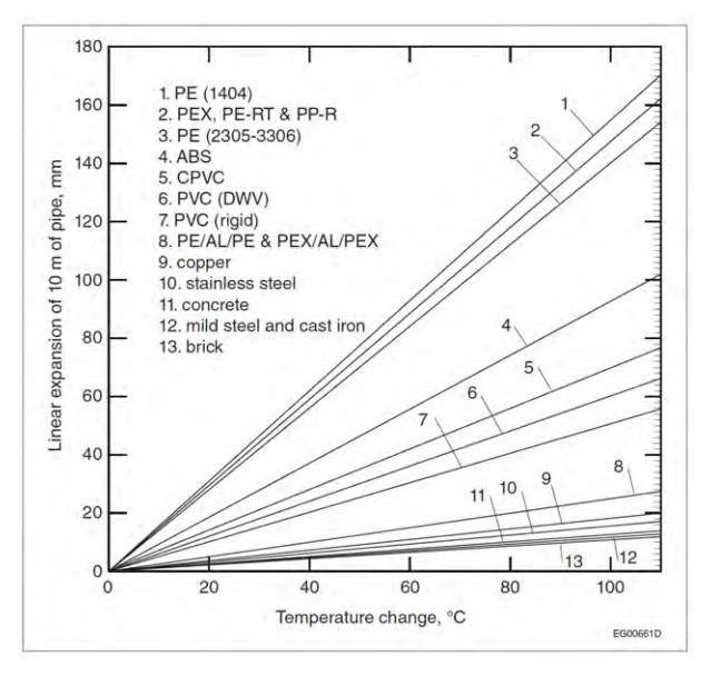
Example:
To determine the expansion of 20 m of ABS pipe for a temperature change from 10°C to 60°C. Temperature change is 60 – 10 = 50°C
Enter the chart at 50°C, read up to the ABS line (#4), and then across to the mm scale. 47 mm/10 m of pipe therefore the change in length over 20 m is 20/10 X 47 = 94 mm
A-7.3.4.6.(1) Support for Underground Horizontal Piping. Copy linkAdd bookmark
Code compliant drain, waste and vent piping of polymeric plastic having schedule 40 dimensions must be installed with select piping bedding where the fill over the pipe will be subject to vehicular traffic or where the burial depth exceeds eight feet.
Sewer pipe of polymeric plastic conforming to a standard that requires a minimum pipe stiffness of 320 kPa shall be installed with select pipe bedding where the fill over the pipe will be subject to vehicular traffic or where the burial depth measured from the top of the pipe exceeds 750 mm.
Select pipe bedding consists of a non-cohesive ballast material of which at least 50% will pass a ¼ inch sieve and 100% will pass a ½ inch sieve, and that completely surrounds the pipe by a radial depth of at least four inches and that is sufficiently consolidated so that the intended earth loading will not produce further compaction.
A-7.3.4.9. Thrust Blocking. Copy linkAdd bookmark
Concrete thrust blocks may be used to provide restraint for underground water service piping. They are readily utilized in combination with tie rods, structural restraining, thrust collars and restrained joints. Thrust blocks are generally categorized as gravity blocks or bearing blocks. Important factors which may affect gravity block design are pipe sizes, water pressure, density of block material and allowable soil bearing pressure that will determine the minimum size of the block base. Publications of pipe and fitting manufacturers show methods for installing thrust blocks at different fittings. In each case, the trench is cut to provide a bearing surface on undisturbed soil, and concrete is placed to fit snugly against as much of the fitting as possible without interfering with access to fitting joints. Sometimes anchor rods may be used to hold the fitting against the blocks.
A-7.3.5.1.(1) Backfilling of Pipe Trench. Copy linkAdd bookmark
Stronger pipes may be required in deep fill or under driveways, parking lots, etc., and compaction for the full depth of the trench may be necessary.
Bedding is required primarily to provide uniform and adequate longitudinal support under the pipe. All drainage pipe shall be supported in such a manner as to maintain its alignment, and prevent sagging. Blocking alone shall not be used to maintain pipe grading. Bell holes at each joint shall be provided to permit the joint to be assembled properly while maintaining uniform pipe support. A compacted depth of 100 mm to 150 mm is generally sufficient bedding thickness. Ledge or sharp rocks and clods which could damage the pipe cannot be used. In general, select pipe bedding shall consist of a non-cohesive ballast material of which at least 50% will pass a ¼ inch sieve and 100% will pass a ½ inch sieve, and that completely surrounds the pipe by a radial depth of at least 100 mm and that is sufficiently consolidated so that the intended earth loading will not produce further compaction.
A-7.3.5.4.(1) Freeze Protection. Copy linkAdd bookmark
Piping Exposed to FreezingCopy linkAdd bookmark
No water, soil, or waste pipes shall be installed on the exterior of a building or in the uninsulated side of an exterior wall, or in any place where they may be subjected to freezing temperatures, unless adequate provision is made to protect such pipes from freezing (such as applying trace wires or insulation).
The Thermal Insulation Association of Canada (TIAC) “Mechanical Insulation Best Practices Guide” 2013 edition is a comprehensive source of information on the selection, installation and proper use of thermal insulation materials. (Note that Section 4 of this Guide is not included in the scope of this Appendix Note as it contains information on proprietary products, which are not within the mandate of the Code.)
Insulation of Buried PipingCopy linkAdd bookmark
Failures in buried pipe are caused by improper installation, corrosion, poor design, soil movement caused by freeze-thaw situations, to name some of the causes. Designing for frost protection is a consideration in Ontario because all regions experience winter conditions, where temperatures drop below freezing, and it is impractical to bury piping below the depth of frost penetration, insulation may be used to protect the pipe from freezing temperatures.
There are two methods available:
- (1) insulation is formed to fit around and encapsulate the pipe, or
- (2) a sheet of insulation at some level above the buried pipe.
The type of backfill that is used to bury pipe is most important because this determines how the frost will pass through the backfill and penetrate the buried pipe.
Typical Water Pipe Protection by Horizontal InsulationCopy linkAdd bookmark
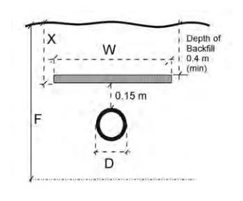
The width of a sheet of insulation may be calculated using the following formula: Width of Insulation:
W = D + 2 (F-X) - 0.3 where:
W = Width of Insulation (m)
D = Outside Diameter of Pipe (m)
X = Insulation Depth (m)
F = Estimated Frost Depth (m)
Having calculated the width of the insulation, the thickness can be found on a chart, similar to the one shown below.
| Design Freezing Index (°C-Days) | ||||||||
|---|---|---|---|---|---|---|---|---|
| 850 | 1 125 | 1 400 | 1 675 | 1 950 | 2 225 | 2 500 | ||
| Amount of Backfill over the Insulation, m | 0.6 | 50 | 65 | 75 | 90 | 100 | 115 | 125 |
| 0.9 | 40 | 50 | 65 | 75 | 90 | 100 | 115 | |
| 1.2 | 25 | 40 | 50 | 65 | 75 | 90 | 100 | |
| 1.5 | 25 | 25 | 40 | 50 | 65 | 75 | 90 | |
| 1.8 | 25 | 25 | 25 | 40 | 50 | 65 | 75 | |
| 2.1 | 25 | 25 | 40 | 50 | 65 | |||
| 2.4 | 25 | 25 | 40 | 50 | ||||
| 2.7 | 25 | 25 | 40 | |||||
| 3.0 | 25 | 25 | ||||||
A-7.3.5.6. Spatial Separation. Copy linkAdd bookmark
The provisions of this Article are intended to limit the probability that failure of an in-ground building drain or building sewer would lead to the contamination of potable water in a water service pipe.
Sentence (1) requires that a minimum 2 440 mm horizontal clearance be provided between a water service pipe and a building drain or a building sewer.
Sentence (2) describes certain exceptions which would permit the water service pipe to be closer than 2 440 mm to the building drain or building sewer.
Sentence (3) recognizes that in certain instances, the water service pipe and a building drain or building sewer may have to cross each other. In this case, the greatest risk of contamination to the potable water is through joints in the water service pipe under backflow conditions. In order to avoid this, the Code requires that there be no joints in the water service pipe within 2 440 mm horizontally of the intersection with the building drain or building sewer. The illustration below appears to meet this requirement, however it is intended that no joints in the water service line be located within 2 440 mm of the closest point on the building drain/sewer.
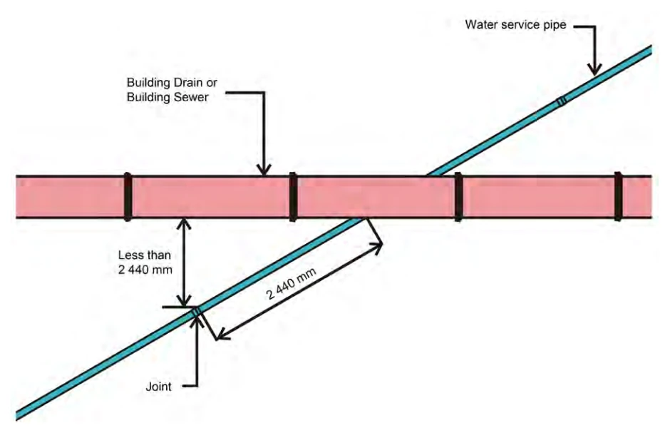
A-7.3.6.5.(1) Air Pressure Tests. Copy linkAdd bookmark
The addition of a non-toxic indicating substance, such as an aerosol, fluorescent dye, smoke or an odorant, to an air pressure test may help in identifying the location of a leak. However, the additive must be compatible with the piping material being tested: the intent is to identify the leak without affecting the outcome of the test or the integrity of the plumbing system.
A-7.4.2.1.(4) Suds Pressure Zones. Copy linkAdd bookmark
High sudsing detergents used in clothes washers produce suds that tend to disrupt the venting action of the venting systems and can also spread through the lower portions of a multi-storey drainage system. The more turbulence, the greater the suds. One solution that avoids the creation of suds pressure zones involves connecting the suds-producing stack downstream of all other stacks and increasing the size of the horizontal building drain to achieve a greater flow of air and water. Using streamlined fittings, such as wyes, tends to reduce suds formation. Check valves or backwater valves in fixture outlet pipes have also been used to correct problem installations.
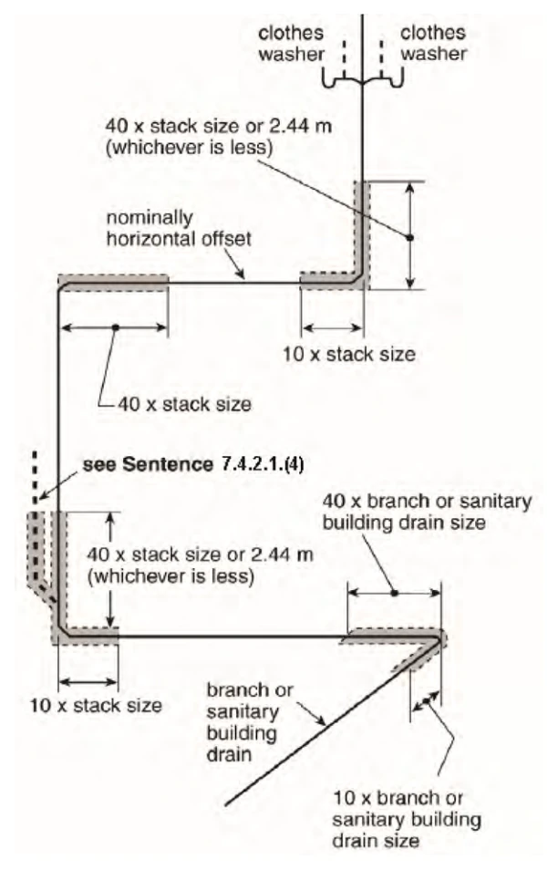
A-7.4.3.3.(1) Waste with Organic Solids. Copy linkAdd bookmark
Equipment such as garbage grinders and potato peelers produce waste with organic solids. These devices reduce most waste into small particles that will flow easily through the drainage system. However, if they are located upstream of the interceptor, the particles could block the interceptor.
A-7.4.4.2.(1) Protection for Drainage System. Copy linkAdd bookmark
When the temperature of the heated discharge exceeds 75°C, the material being used shall be used in accordance with the manufacturer’s approval and done in accordance with the manufacturer’s instructions. Where the material being used is a thermoplastic, care should be taken with discharges above 55°C.
A-7.4.4.3.(1) Grease Interceptors. Copy linkAdd bookmark
For large volume engineered interceptors, the drain down time may vary. Grease interceptors may be required when it is considered that the discharge of fats, oil or grease may impair the drainage system. Further information on the design and sizing of grease interceptors can be found in the ASPE 2012, “Plumbing Engineering Design Handbook, Volume 4, Chapter 8, Grease Interceptors”.
A-7.4.4.4.(1) Hazardous Waste. Copy linkAdd bookmark
Chemically loaded and bio-hazardous wastes can be dangerous to private and public sewer systems and hazardous to people. The treatment of corrosive and acid waste is mandated by this Code.
The treatment of chemically loaded effluents is usually regulated by sewage collecting and treatment authorities. The treatment of bio-hazardous waste should follow good engineering practice, such as that described in the Laboratory Biosafety Guidelines published by Health Canada. Bio-hazardous waste disposal systems require specific engineering expertise and remain outside the scope of this Code.
A-7.4.5.1.(5) Location of Trap or Interceptor. Copy linkAdd bookmark
An interceptor that replaces a trap must be vented in the same way as the trap it replaces. (See Note A-7.4.2.1.(1)(a)(ii) and (e)(vi)) Where an interceptor other than an oil interceptor serves a group of fixtures requiring more than one trap, each fixture must be properly trapped and vented. (See Article 7.5.5.2. for venting of oil interceptors.)
A-7.4.5.2.(1) Untrapped Leader. Copy linkAdd bookmark
When an untrapped leader drains to a combined building sewer, clearance requirements are the same as for vent terminals. (See also Note A-7.5.6.5.(4))
A-7.4.6.3. Arrangement of Piping at Sump. Copy linkAdd bookmark
In most installations, controls will be installed in conjunction with a float to automatically empty the sump. If such controls are not provided, the capacity of the sump should equal the maximum inflow to the sump that is expected to occur during any 24 h period.
A-7.4.6.4. Protection from Backflow Caused by Surcharge. Copy linkAdd bookmark
These requirements are intended to apply when, in the opinion of the local authority having jurisdiction, there is danger of backup from a public sewer.
A-7.4.7.1.(1) Cleanouts for Fixture Drains. Copy linkAdd bookmark
A trap cleanout plug is not acceptable as a cleanout for the fixture drain; hence, either a separate cleanout or a trap with a removable trap dip must be installed.
A-7.4.7.1.(6) Cleanouts for Drainage Systems. Copy linkAdd bookmark
To accommodate the limitations of sewer cleaning equipment, the cleanout should be located as close as possible to the exterior wall of the building, either inside or outside, and be accessible for sewer cleaning equipment.
A-7.4.8.1.(1) Minimum Slope. Copy linkAdd bookmark
Although slopes below 1 in 100 are permitted for pipes over NPS 4, they should be used only where necessary. Steeper slopes and higher velocities will help to keep pipes clean by moving heavier solids that might tend to clog the pipes.
A-Table 7.4.9.3. Hydraulic Loads. Copy linkAdd bookmark
Bathroom GroupCopy linkAdd bookmark
A bathroom group is considered to consist of 1 water closet, 1 lavatory, and 1 bathtub (with or without shower head) or a shower stall.
Hydraulic Loads for Laundry TrapsCopy linkAdd bookmark
When determining the hydraulic load on a pipe, no allowance need be made for a load from a domestic clothes washer when discharged into a laundry tray, since the hydraulic load from the laundry tray is sufficient.
Hydraulic Loads for Floor DrainsCopy linkAdd bookmark
No hydraulic load is required from a floor drain in a washroom since it is for emergency use only.
A-7.4.9.3.(2) Continuous Wastes. Copy linkAdd bookmark
Fixture outlet pipes that are common to 2 or 3 compartments or fixtures are sometimes referred to as continuous wastes and are not considered to be branches. (See also Note A-7.4.5.1.(2).)
A-7.4.10.4.(1) Rainfall Intensities. Copy linkAdd bookmark
Climate information on rainfall intensities for various localities is found in MMAH Supplementary Standard SB-1, “Climatic and Seismic Data”.
When calculating the hydraulic load from a roof or paved surface, it should be noted that a 1 mm depth of water on 1 m2 of surface is equivalent to 1 L.
A-Table 7.4.10.5. Conversion of Fixture Units. Copy linkAdd bookmark
The following table expands Table 7.4.10.5.:
| Fixture Units in Service | Fixture Units Col. 1 | Fixture Units Col. 1 x 10 | Fixture Units Col. 1 x 100 |
|---|---|---|---|
| 10 | 21 | 53 | 174 |
| 11 | 23 | 55 | 183 |
| 12 | 24 | 57 | 192 |
| 13 | 24 | 59 | 201 |
| 14 | 25 | 61 | 210 |
| 15 | 25 | 63 | 219 |
| 16 | 26 | 65 | 228 |
| 17 | 26 | 67 | 237 |
| 18 | 27 | 69 | 246 |
| 19 | 27 | 71 | 254 |
| 20 | 27 | 72 | 262 |
| 21 | 28 | 74 | 271 |
| 22 | 29 | 75 | 280 |
| 23 | 29 | 77 | 289 |
| 24 | 30 | 78 | 298 |
| 25 | 30 | 80 | 307 |
| 26 | 31 | 82 | 316 |
| 27 | 31 | 83 | 325 |
| 28 | 32 | 85 | 334 |
| 29 | 32 | 86 | 342 |
| 30 | 33 | 88 | 350 |
| 31 | 33 | 90 | 359 |
| 32 | 34 | 91 | 368 |
| 33 | 34 | 92 | 377 |
| 34 | 35 | 94 | 386 |
| 35 | 35 | 95 | 395 |
| 36 | 36 | 96 | 403 |
| 37 | 36 | 98 | 411 |
| 38 | 37 | 99 | 419 |
| 39 | 37 | 100 | 427 |
| 40 | 38 | 102 | 435 |
| 41 | 38 | 103 | 444 |
| 42 | 39 | 104 | 453 |
| 43 | 39 | 106 | 462 |
| 44 | 39 | 107 | 471 |
| 45 | 40 | 108 | 480 |
| 46 | 40 | 110 | 488 |
| 47 | 40 | 111 | 496 |
| 48 | 41 | 112 | 504 |
| 49 | 41 | 114 | 512 |
| 50 | 41 | 115 | 520 |
| 51 | 42 | 116 | 528 |
| 52 | 42 | 118 | 536 |
| 53 | 42 | 119 | 544 |
| 54 | 43 | 120 | 552 |
| 55 | 43 | 122 | 560 |
| 56 | 43 | 123 | 568 |
| 57 | 44 | 124 | 576 |
| 58 | 44 | 126 | 584 |
| 59 | 44 | 127 | 592 |
| 60 | 44 | 128 | 600 |
| 61 | 45 | 129 | 608 |
| 62 | 45 | 130 | 616 |
| 63 | 45 | 131 | 624 |
| 64 | 45 | 133 | 632 |
| 65 | 46 | 134 | 640 |
| 66 | 46 | 135 | 648 |
| 67 | 46 | 136 | 656 |
| 68 | 46 | 138 | 664 |
| 69 | 47 | 139 | 672 |
| 70 | 47 | 140 | 680 |
| 71 | 47 | 141 | 687 |
| 72 | 47 | 143 | 694 |
| 73 | 48 | 144 | 701 |
| 74 | 48 | 145 | 708 |
| 75 | 48 | 147 | 715 |
| 76 | 48 | 148 | 722 |
| 77 | 49 | 149 | 729 |
| 78 | 49 | 151 | 736 |
| 79 | 49 | 152 | 743 |
| 80 | 49 | 153 | 750 |
| 81 | 50 | 154 | 759 |
| 82 | 50 | 155 | 768 |
| 83 | 50 | 156 | 777 |
| 84 | 50 | 157 | 786 |
| 85 | 50 | 159 | 795 |
| 86 | 51 | 160 | 803 |
| 87 | 51 | 161 | 811 |
| 88 | 51 | 162 | 819 |
| 89 | 51 | 163 | 827 |
| 90 | 51 | 164 | 835 |
| 91 | 52 | 165 | 842 |
| 92 | 52 | 166 | 849 |
| 93 | 52 | 167 | 856 |
| 94 | 52 | 168 | 863 |
| 95 | 52 | 169 | 870 |
| 96 | 53 | 170 | 876 |
| 97 | 53 | 171 | 882 |
| 98 | 53 | 172 | 888 |
| 99 | 53 | 173 | 894 |
| 100 | 53 | 174 | 900 |
A-7.5.4.5.(1) Fixture Connections to Vent Pipes. Copy linkAdd bookmark
When one or more fixture drains are connected to a vent pipe, the vent pipe becomes a wet vent. It must then conform to all the requirements that can apply to it as a drainage pipe and a vent pipe.
A-7.5.6.2.(2) Vent Pipe Connections. Copy linkAdd bookmark
Except for wet venting, fittings used to connect vent pipes to nominally horizontal soil-or-waste pipes are specified in Subsection 7.2.4.
A-7.6.1.3.(5) Shut-off Valves. Copy linkAdd bookmark
Where multiple risers convey the water supply to dwelling units, each dwelling unit's water distribution system shall be provided with a shut-off valve located immediately where the water piping enters the suite so as to isolate the fixtures as well as the water distribution piping serving the dwelling unit's fixtures. Fixture stopcocks or shut-off valves located immediately adjacent to a fixture may not be adequate to protect the water distribution piping. Where a dwelling unit is served by a single shut-off valve on the water supply, additional shut-off valves may be required to achieve compliance with Sentences 7.6.1.3.(4) and (7).
A-7.6.1.3.(9) Identification of Underground Non-Metallic Pipe. Copy linkAdd bookmark
Metallic piping may be used to extend underground non-metallic water supply piping above the floor. In these cases, the metallic pipe extension should not be used for electrical grounding purposes. Therefore, it is advisable to post a permanent sign indicating “plastic piping underground - do not use for electrical grounding purposes” in a conspicuous location.
A-7.6.1.5.(1) Check Valves. Copy linkAdd bookmark
When a check valve is required by Sentence 7.6.1.5.(1), or a backflow preventer by Articles 7.6.2.2., 7.6.2.3. or 7.6.2.6. or a pressure reducing valve by Article 7.6.3.3., protection against thermal expansion may be required.
A-7.6.1.6.(4.1) Plumbing Fixtures. Copy linkAdd bookmark
Heritage buildings including homes, may contain sanitary drainage piping that is sized in accordance with the flush cycle of period plumbing fixtures. Operational difficulties maybe encountered when these fixtures are replaced with one having a lower flush cycle.
A-7.6.1.6.(5) Flush-Tank-Type Urinals in Seasonal Buildings. Copy linkAdd bookmark
Flush-tank-type urinals that are not in use for an extended period of time, such as those in seasonal buildings, are permitted to be set up to flush automatically at predetermined intervals. Automatic flushing prevents the depletion of the water seal due to evaporation or backflow conditions. The trap seal restricts the infiltration of gases, which can pose health and safety concerns.
A-7.6.1.7. Relief Valves. Copy linkAdd bookmark
A relief valve shall not be routed through or discharge to an area where freezing temperatures may occur.
If the discharge piping is longer than 2 m or more than two 90° elbows are used, the valve manufacturer’s installation instructions should be followed to ensure that the piping does not affect the relief valve’s discharge capacity.
A-7.6.1.7.(5) Relief Valves. Copy linkAdd bookmark
If the discharge piping is longer than 2 m or more than two 90° elbows are used, the valve manufacturer's installation instructions should be followed to ensure that the piping does not affect the relief valves' discharge capacity.
A-7.6.1.9.(1) Water Hammer Prevention. Copy linkAdd bookmark
Water hammer is a build-up of pressure in a length of horizontal or vertical pipe which occurs when a valve or faucet is closed suddenly. The longer the pipe and the greater the water velocity, the greater the pressure exerted on the pipe, which can be many times the normal static water pressure and be sufficient to burst the pipe. Ordinary kitchen and bathroom faucets can be closed quickly enough to cause water hammer even with relatively low water pressure in the pipe.
Means of preventing water hammer should be installed wherever there are valves or faucets, particularly where they are at the end of long lengths of pipes. This may be done by installing either water hammer arresters which are manufactured for the purpose or air chambers installed vertically that are fabricated from pieces of piping with a closed upper end and connected to the end of the horizontal or vertical run of pipe.
The air chamber should be 300 to 450 mm long if made from the same size pipe as the water pipe it serves. If the chamber is made from a pipe with larger diameter than the water pipe, its length can be reduced accordingly.
Air chambers should be accessible if they are the manufactured type with top air valve and a stop-and-waste valve or are of the diaphragm type.
A-7.6.1.11.(1) Thermal Expansion. Copy linkAdd bookmark
To accommodate the increase in pressure caused by thermal expansion within a closed water system, one of the following should be installed:
- (1) a suitably sized diaphragm expansion tank designed for use within a potable water system,
- (2) an auxiliary thermal expansion relief valve (T.E.R. valve) conforming to CAN/CSA-B125.3, “Plumbing Fittings”, set to a pressure of 550 kPa or less and designed for repeated use, or
- (3) other means acceptable to the authority having jurisdiction.
A-7.6.2.5A. Backflow from Buildings with a Solar Domestic Hot Water System. Copy linkAdd bookmark
The Building Code regulates where a backflow preventer is required. Articles 7.6.2.1.and 7.6.2.2. require protection of potable water systems against contamination due to reversal of the normal direction of flow between a potable water system and any other system containing non-potable water or substances, where there is a direct connection between the two systems.
Consequently, a backflow prevention device is required in a solar domestic hot water (SDHW) system only where there is a direct connection between the building’s potable water make-up supply and the solar heat transfer loop containing non-potable fluids. Where a non-potable heat transfer loop is charged with potable water through a charging port that is not permanently connected to a potable water system, the temporary connection to the potable water system shall include a backflow preventer or an air gap.
Equipment forming part of a packaged system for solar heating of potable water must conform to CAN/CSA-F379.1, “Packaged Solar Domestic Hot Water Systems (Liquid-to-Liquid Heat Transfer)”. The installation of packaged systems for solar heating of potable water in residential occupancies must be in conformance with CSA F383, “Installation of Packaged Solar Domestic Hot Water Systems”. All other systems must be installed in accordance with good engineering practice and are expected to comply, where applicable, with the same practices required for package systems.
According to Clause 7.4.3.1. of CAN/CSA-F379.1, a SDHW system that utilizes a single-wall heat exchanger is required to contain a relatively harmless heat transfer fluid (which may present minor to moderate hazard) and be properly labelled. In this case, a permanent backflow prevention device would be required on the charging line between the potable water system and the heat transfer loop only if there is a permanent direct connection between the heat transfer loop and the potable water system. Otherwise, the Building Code does not require backflow prevention devices on the domestic hot or cold potable water lines. In case of a conflict between the provisions of the Building Code and the standard, the provisions of the Building Code govern.
Similarly, where a SDHW system has a double-wall heat exchanger and there is a permanent direct connection between the heat transfer loop and the potable water system, the selection of the required backflow preventer would be determined in accordance with Sentence 7.6.2.3.(1), based on the type of heat transfer fluid used and other risks.
The requirement for premise isolation would be determined based on the use and the occupancy of the entire building. In most cases, the installation of a domestic solar hot water system that has a direct connection to a potable water system, alone, would not require the premise isolation referenced in Sentence 7.6.2.6.(1).
“Relatively harmless” as defined in CAN/CSA-F379.1, “Packaged Solar Domestic Hot Water Systems (Liquid-to-Liquid Heat Transfer)” as a fluid having an oral LD50 of 15 000 mg/kg or greater, in accordance with Toxicity Class 6 (relatively harmless) of the Hodge and Sterner scale. The Hodge and Sterner scale is a toxicity scale recognized by the Canadian Centre for Occupational Health and Safety that provides ratings from 1 (extremely toxic) to 6 (relatively harmless) based on the LD50 approach for oral administration. LD stands for “Lethal Dose”. LD50 is the amount of a material, given all at once, which causes the death of 50% (one half) of a group of test animals. The LD50 is one way to measure the short-term poisoning potential (acute toxicity) of a material.
Information is published in the material safety data sheets supplied with all heat-transfer fluid shipments, as required by Canadian law.
A-7.6.2.6. Locations Requiring Premise Isolation. Copy linkAdd bookmark
The following list is a guide to locations where premise isolation may be considered a moderate hazard:
- shopping malls
- multi-unit residential
- office buildings
- pleasure boat marinas
- schools and colleges
The following list is a guide to locations where premise isolation may be considered a severe hazard:
- hospital buildings with operating, mortuary or laboratory facilities
- radioactive material processing plants
- petrochemical processing facilities
- premises where inspection is restricted
- sewage treatment plants
- commercial laundries (excluding laundromats)
- plating or chemical plants
- docks and dockside facilities
- food and beverage processing plants
- steam plants
- trackside facilities for trains
An assessment of the hazard must be carried out to determine the need, if any, for a backflow prevention device.
A-7.6.2.8.(1) Flushing and Disinfecting Water Service Pipes. Copy linkAdd bookmark
Water service pipes of 100 mm in size or larger shall be flushed and disinfected. Flushed sections shall be protected from contamination.
After flushing is completed, water from the existing distribution system shall be allowed to flow at a controlled rate into the new piping. Liquid chlorine solution shall be introduced so that the chlorine is distributed throughout the section being disinfected. The chlorine shall be applied so that the chlorine concentration is 50 mg/L minimum throughout the section. Then the system shall be left charged with 50 mg/L chlorine solution for 24 hours.
Test the chlorine residual piping after 24 hours. If tests indicate a chlorine residual of at least 25 mg/L, the section shall be flushed completely and recharged with water normal to the operation of the system. If the test does not meet the requirements, the chlorination procedure shall be repeated until satisfactory results are obtained. After the system has been recharged, take samples for bacteriological tests. If there is indication of contamination, the disinfection procedure shall be repeated. The system shall not be put into operation until clearance has been given by the inspector appointed by the chief building official.
A-7.6.3. Water Systems. Copy linkAdd bookmark
Subsection 7.6.3. contains performance requirements for water systems. Two widely used references for the design of water systems are:
- NIST Building Materials and Structures Report BMS 79, “Water-Distributing Systems for Buildings,” United States Department of Commerce, National Bureau of Standards, Washington, D.C., and
- McGraw-Hill 2009, “International Plumbing Codes Handbook,” edited by V.T. Manas, McGraw-Hill Book Company, New York, U.S.A.
A-7.6.3.1. Water Quality. Copy linkAdd bookmark
Water destined for use as potable water can originate from a variety of sources that are generally classified as surface waters or well waters, such as lakes, rivers, streams and aquifers. In some localities, there may be seasonal variations in the water supply, and surface and well waters may be blended at times.
Water composition is the primary consideration in determining the cause of corrosion in potable water systems. If the water has corrosive characteristics, water treatment may be necessary to control its corrosiveness: this may be as straightforward as adjusting the pH of the water at the treatment plant, or it may involve more extensive corrosion-control treatment methods. Water purveyors normally consult treatment specialists to develop methods suitable for specific conditions. The treatment of water from private wells may also require expert consultation.
The past performance of plumbing materials and products in different localities often provides insight into what can be expected with new installations. In areas where water-related corrosion is known to occur, adjustment of water chemistry may be sufficient, or it may be necessary to select alternative piping and fitting materials or more robust products.
It is important to note that not all corrosion can be attributed to water conditions: the improper design and installation of potable water systems may result in erosion corrosion, galvanic corrosion, fatigue cracking, and so forth.
A-7.6.3.1.(2) Design of Potable Water Systems. Copy linkAdd bookmark
The design procedures contained in the following documents are considered good engineering practice in the field of potable water systems:
- (a) 2011 ASHRAE Handbook of HVAC Applications, Chapter 50, “Service Water Heating”,
- (b) 2009 ASHRAE Handbook of Fundamentals, Chapter 22, “Pipe Sizing”,
- (c) 2005 ASPE Data Book - Volume 2, Chapter, 5, “Cold Water Systems”, and
- (d) 2005 ASPE Data Book - Volume 2, Chapter, 6, “Domestic Water Heating Systems Fundamentals”. Alternative procedures shown below are also acceptable.
| Water Service, inches | Water Distribution System, inches | Maximum Allowable Length, m | ||||||||||||||
|---|---|---|---|---|---|---|---|---|---|---|---|---|---|---|---|---|
| 12 | 18 | 24 | 30 | 46 | 61 | 76 | 91 | 122 | 152 | 183 | 213 | 244 | 274 | 305 | ||
| Pressure Range | Number of Fixture Units Served | |||||||||||||||
| 200 to 310 kPa (30 to 45 psi) | ||||||||||||||||
| ¾” | ½” | 6 | 5 | 4 | 3 | 2 | 1 | 1 | 1 | 0 | 0 | 0 | 0 | 0 | 0 | 0 |
| ¾” | ¾” | 18 | 16 | 14 | 12 | 9 | 6 | 5 | 5 | 4 | 4 | 3 | 2 | 2 | 2 | 1 |
| ¾” | 1" | 29 | 25 | 23 | 21 | 17 | 15 | 13 | 12 | 10 | 9 | 7 | 6 | 6 | 6 | 6 |
| 1" | 1" | 36 | 31 | 27 | 25 | 20 | 17 | 15 | 13 | 12 | 10 | 8 | 6 | 6 | 6 | 6 |
| 1½" | 1¼” | 90 | 68 | 57 | 48 | 38 | 32 | 28 | 25 | 21 | 18 | 15 | 12 | 12 | 11 | 11 |
| 1½" | 1½" | 151 | 124 | 105 | 91 | 70 | 57 | 49 | 45 | 36 | 31 | 26 | 23 | 21 | 20 | 20 |
| 2" | 1½" | 151 | 151 | 132 | 110 | 80 | 64 | 53 | 46 | 38 | 32 | 27 | 23 | 21 | 20 | 20 |
| 2" | 2" | 359 | 329 | 292 | 265 | 217 | 185 | 164 | 147 | 124 | 96 | 70 | 61 | 57 | 54 | 51 |
| 2½" | 2½” | 445 | 418 | 390 | 370 | 330 | 300 | 280 | 265 | 240 | 220 | 198 | 175 | 158 | 143 | 133 |
| 311 to 413 kPa (46 to 60 psi) | ||||||||||||||||
| ¾” | ½” | 8 | 7 | 6 | 5 | 4 | 3 | 2 | 2 | 1 | 1 | 1 | 0 | 0 | 0 | 0 |
| ¾” | ¾” | 21 | 21 | 19 | 17 | 14 | 11 | 9 | 8 | 6 | 5 | 4 | 4 | 3 | 3 | 3 |
| 1" | 1" | 42 | 42 | 41 | 36 | 30 | 25 | 23 | 20 | 18 | 15 | 12 | 10 | 9 | 8 | 8 |
| 1½" | 1¼” | 83 | 83 | 83 | 83 | 66 | 52 | 44 | 39 | 33 | 29 | 24 | 20 | 19 | 17 | 16 |
| 1½" | 1½" | 151 | 151 | 151 | 151 | 128 | 105 | 90 | 78 | 62 | 52 | 42 | 38 | 35 | 32 | 30 |
| 2" | 1½" | 151 | 151 | 151 | 151 | 150 | 117 | 98 | 84 | 67 | 55 | 42 | 38 | 35 | 32 | 30 |
| 2" | 2" | 359 | 359 | 359 | 359 | 359 | 318 | 280 | 250 | 205 | 165 | 142 | 123 | 110 | 102 | 94 |
| 2½" | 2½” | 611 | 611 | 610 | 580 | 535 | 500 | 470 | 440 | 400 | 365 | 335 | 315 | 285 | 267 | 250 |
| Over 413 kPa (60 psi) | ||||||||||||||||
| ¾” | ½” | 8 | 8 | 7 | 6 | 5 | 4 | 3 | 3 | 2 | 1 | 1 | 1 | 1 | 1 | 0 |
| ¾” | ¾” | 21 | 21 | 21 | 21 | 17 | 13 | 11 | 10 | 8 | 7 | 6 | 6 | 5 | 4 | 4 |
| 1" | 1" | 42 | 42 | 42 | 42 | 38 | 32 | 29 | 26 | 22 | 18 | 14 | 13 | 12 | 12 | 11 |
| 1½" | 1¼” | 83 | 83 | 83 | 83 | 83 | 74 | 62 | 54 | 43 | 34 | 26 | 25 | 23 | 22 | 21 |
| 1½" | 1½" | 151 | 151 | 151 | 151 | 151 | 151 | 130 | 113 | 88 | 73 | 51 | 51 | 46 | 43 | 40 |
| 2" | 1½" | 151 | 151 | 151 | 151 | 151 | 151 | 142 | 122 | 98 | 82 | 64 | 51 | 46 | 43 | 40 |
| 2" | 2" | 359 | 359 | 359 | 359 | 359 | 359 | 359 | 340 | 288 | 245 | 204 | 172 | 153 | 141 | 129 |
| 2½” | 2½” | 611 | 611 | 611 | 611 | 611 | 611 | 610 | 570 | 510 | 460 | 430 | 404 | 380 | 356 | 329 |
Notes to Table A-7.6.3.1.:
A-7.6.3.2.(4) Sizing for Flush Valves. Copy linkAdd bookmark
Distribution piping and water mains serving flush valves may be sized using the values assigned in Tables 7.6.3.2.-B and 7.6.3.2.-C, beginning with the most remote flush valve on each section of distribution piping served by the water main.
A-7.6.3.4.(5) Water System Pipe Size. Copy linkAdd bookmark
Where separate water service piping connects into private water supply piping, the private water supply piping will be governed by Article 7.1.5.5.
A-7.6.4.1.(1) and (2) Automatic Shut-off of Water Flow. Copy linkAdd bookmark
Examples of water shut-off devices include occupant sensors and self-closing valves.
A-7.6.4.1.(3) Automatic Compensating Valves. Copy linkAdd bookmark
When replacing a shower head, the appropriate shower valve with a suitable compensating feature matching the flow rate should be chosen to decrease the possibility that users will suffer thermal shock. The water flow rate of automatic compensating mixing valves can be found in ASSE 1016 / ASME 112.1016 / CSA B125.16, “Performance Requirements for Automatic Compensating Valves for Individual Showers and Tub/Shower Combinations”.
A-7.7.1.1. Non-Potable Water System Design. Copy linkAdd bookmark
There is a growing interest in Canada in using available non-potable water supplies in the place of potable ones for selected purposes such as flushing water closets and irrigating lawns and gardens. Article 7.7.1.1. applies to non-potable water systems, regardless of the origin of the water. The non-potable water must meet applicable water quality standards as determined by an authority having jurisdiction.
A-7.7.1.1.(1) Good Engineering Practice. Copy linkAdd bookmark
Examples of good engineering practice in the design, fabrication and installation of non-potable water systems can be found in
- the ASHRAE Handbooks,
- the ASPE Handbooks, and
- CAN/CSA-B128.1, “Design and Installation of Non-Potable Water Systems.”
A-7.7.2.1.(1) Aboveground Roof Surfaces. Copy linkAdd bookmark
While it is possible to harvest rainwater from surfaces other than above-ground roofs, such as patios, lawns, gardens, driveways, roadways, parking garages and parking lots, these surfaces are not suitable catchments for rainwater harvesting systems because of water quality concerns. Water collected from such surfaces may be contaminated with fertilizer, herbicides, fecal matter, garbage, oil or chemicals.
The outdoor environment in the local area of the building site, including its immediate surroundings, should be investigated to identify contaminants that could adversely affect the quality of the non-potable water delivered by the rainwater harvesting system. Contaminants of concern include industrial and urban traffic emissions, and pesticides and other agricultural chemicals. Other factors that can influence the levels of contaminants in the delivered non-potable water include the building's geometry, and prevailing winds and seasonal activity in the local area. Design features should be incorporated in the rainwater harvesting system to mitigate the risks associated with any identified contaminants of concern.
A-7.7.2.2.(1) and 7.7.2.4.(3) and (4) Treatment for Use. Copy linkAdd bookmark
Harvested rainwater used in any permitted application must be treated appropriately for its intended end use.
A-7.7.2.3.(1) Pedestrian Traffic. Copy linkAdd bookmark
The prohibition of pedestrian traffic on roof surfaces stated in Sentence 7.7.2.3.(1) is not intended to include access to roof surfaces by service personnel, such as window washers or HVAC mechanics.
A-7.7.2.3.(2) Roofing and Conveyance Materials. Copy linkAdd bookmark
Water is considered to be the “universal solvent.” Accordingly, roofing components and conveyance systems that supply rainwater to a rainwater harvesting system should be constructed of materials that resist dissolution in water. NSF Pro 151-8-1, “Health Effects from Rainwater Catchment System Components,” although directed at potable water systems, is a useful source of information on roofing materials to consider.
A-7.7.2.4.(1) Good Engineering Practice. Copy linkAdd bookmark
Examples of good engineering practice in the design, fabrication and installation of rainwater harvesting systems can be found in
- the ASHRAE Handbooks,
- the ASPE Handbooks,
- ARCSA/ASPE/ANSI 63, “Rainwater Catchment Systems,” and
- CSA B805/ICC 805, “Rainwater harvesting systems.”
A-8.1.3.1.(1) Sanitary Sewage. Copy linkAdd bookmark
Sanitary sewage of domestic origin is as described in (b) of the definition in Sentence 1.4.1.2.(1) of Division A. The addition of public swimming pool drainage to the definition of sanitary sewage is not intended to allow the discharge of the pool drainage water to an on-site sewage system.
A-8.1.3.1.(3) Evaluation of Waste from Industrial Processes. Copy linkAdd bookmark
When evaluating whether industrial process waste can go to an on-site sewage system, the total contaminant levels in the whole waste stream must be looked at. Heavy metals, pesticides and solvents are not found in domestic sewage and those levels must be brought down if present. The BOD5 and suspended solids should be consistent with the levels found in domestic sanitary sewage. Slaughterhouses and milking operations have wastes that are similar to domestic sewage in chemical composition, but are characterized by high organic, highly nitrogenous and biologically degradable suspended and dissolved solids and grease in high concentrations. These wastes are not suitable for discharge to an on-site sewage system.
A-8.2.1.2.(1) Site Evaluation Information. Copy linkAdd bookmark
The evaluation required in Sentence (1) usually includes at least the following and is required on permit application
- (a) date the evaluation was done,
- (b) name, address, telephone number, and signature of the person who prepared the evaluation,
- (c) a scaled plan of the site showing
- (i) the legal description of the property, property lines and easements,
- (ii) the location of items in Column 1 of Tables 8.2.1.6.A. and 8.2.1.6.B.,
- (iii) the proposed location of the sewage system,
- (iv) the location of any unsuitable, disturbed or compacted areas, and
- (v) the access route for tank maintenance,
- (d) depth to bedrock,
- (e) evidence of high ground water,
- (f) soil properties,
- (g) soil conditions,
- (h) utility corridors,
- (i) permeability, and
- (j) potential for flooding.
A-8.2.1.2.(2) Alternative Tests. Copy linkAdd bookmark
Other tests to determine percolation time may be suitable depending on the soil type(s) encountered on a site. The results of tests other than those described in this Code may be used by relying on provisions governing the use of alternative solutions (such as Clause 1.2.1.1.(l)(b) of Division A).
A-8.2.1.2.(3) Test Procedure. Copy linkAdd bookmark
Where a field percolation test is required, it is performed in the following manner:
- (a) Make an excavation in the soil layer which is to be assessed for a percolation time. The excavation shall be:
- (i) between 100 and 300 mm in diameter
- (ii) be at least 200 mm in depth below the upper level of the soil layer being assessed.
- (b) All loose material and smeared clay shall be removed from the sides and bottom of the excavation.
- (c) Cover the bottom of the excavation with 50 mm of sand or fine gravel.
- (d) Fill the hole with water to a depth of 300 mm (or to the surface) and determine the time it takes for the water to seep away; repeat, and if the second filling seeps away in 10 minutes or less proceed as follows:
- Establish a fixed reference point, add water to a depth of 150 mm above the sand or fine gravel, and measure the water drop every 10 minutes for one hour. If for one hour the first 150 mm seeps away in 10 minutes or less, use a shorter time interval between readings.
- Refill to the 150 mm level when necessary and start another series of readings. Continue readings until the last two series of readings show a similar drop pattern (approximately equal drop in the same number of readings) or, alternatively, until the difference in the maximum and minimum drops in 3 consecutive readings is less than 5 mm. In either case use the average drop of the last 3 readings in computing “T”
- (e) If the initial fillings to 300 mm take more than 10 minutes to seep away, follow with this procedure:
- Maintain at least 300 mm of water in the hole for at least 4 hours, or until the soil being tested has become swollen and saturated with water. At least 12 hours should be allowed for swelling in clay soils, although dry clay soils may require longer periods to obtain a stabilized percolation rate.
- After swelling remove any loose material from the top of the sand or fine gravel.
- Using a fixed reference point, adjust the water level to 150 mm above the sand or gravel and measure the water drop every 30 minutes for four hours or until a stable rate of drop is reached. If the first 150 mm seeps away in less than 30 minutes, use a 10 minute interval and run the test for one hour or until the drop rate is stabilized. A drop of 5 mm or less in a 30 minute interval is indicative of a soil of “T” close to or greater than 50 min/cm. If it is to be assessed increase the reading interval to 60 minutes.
- Refill with water to the 150 mm level when necessary. Take readings until a stable rate of drop is reached. This may be when the drop in two successive readings does not vary by more than 1.5 mm or when the difference between the maximum and minimum readings of the last four readings does not exceed 5 mm. Once a stable rate is reached use the average drop of the last 3 readings in computing the percolation time.
- (f) Percolation time = (Time Interval (minutes)) / (Average drop of last 3 readings (cm))
A-8.2.1.3.(1) and (2) Balancing Tanks. Copy linkAdd bookmark
Where variable daily flows or peak flows occur, the flows to the sewage system may be balanced. The sewage system and any pump(s) that are installed to move the sanitary sewage, should be sized to accommodate a daily design sanitary sewage flow at least equal to the average daily sanitary sewage flow for the week. Balancing tanks should be sized in accordance with good engineering practice to ensure that peak flows can be accommodated.
A-8.2.1.4. Clearance Requirements. Copy linkAdd bookmark
Where coarse natural soils exist it may be necessary to require greater clearance distances to wells or surface water than those listed in the Tables. This is of greater importance when applied to the shoreline properties of sensitive lakes, where it is desired to prevent phosphates from entering the lakes.
A-8.4.1.2. Horizontal Greywater Systems. Copy linkAdd bookmark
Consideration can be made for Class 2 greywater systems to be constructed using a horizontal or a linear orientation. In these cases, the loading rate should be calculated using Article 8.4.2.3. “Sizing”.
A-8.6.2.2. Other Treatment Units. Copy linkAdd bookmark
Article 8.6.2.2. sets out the acceptable solution to achieve Building Code compliance for residential treatment units. Sentences (1) and (2) of Article 8.6.2.2. are the performance requirements that set out the maximum concentrations of suspended solids and CBOD5 for different classifications of treatment units.
As set out in Sentence (5), treatment units that are certified to CAN/BNQ 3680-600, “Onsite Residential Wastewater Treatment Technologies” using a temperature condition listed under option a) or b) of Clause 8.2.2. of that standard are deemed to comply with the requirements of Sentences (1) and (2).
CAN/BNQ 3680-600 uses slightly different terminology than the Building Code. Note (1) to Table 8.6.2.2., which forms part of Sentences 8.6.2.2. (1) and (2), states that the classifications of treatment units specified in Column 1 correspond to the levels of treatment described in CAN/BNQ 3680-600. A Building Code Level II treatment unit corresponds to a treatment Class B-II in CAN/BNQ 3680-600, a Level III corresponds to Class B-III, and Level IV corresponds to a Class B-IV.
CAN/BNQ 3680-600 -2009 requires:
- 12 continuous months of testing in a climate representative of Ontario conditions as specified in Annex B.3. of the standard
- A minimum of weekly sampling
- 30-day average concentrations in treated effluent that do not exceed the maximum concentrations set out in Table 8.6.2.2.
- A minimum of 80% of sample results that do not exceed the maximum concentrations set out in Table 8.6.2.2.
- Influent wastewater quality that meets the requirements described in Table 5 of the standard
- Influent wastewater temperature that is:
- Non-controlled, or
- Controlled so that the influent wastewater is heated to no more than 11°C ±1°C,
- Hydraulic loading as specified in Clause 8.2.2.1. of NSF/ANSI Standard 40 and Annex B.4.2.2. of the standard
- Stress loading in accordance with the procedures outlined in CAN/BNQ 3680-600, which includes wash-day stress, power/equipment failure stress, and working parent stress.
Installation of a CAN/BNQ 3680-600 certified residential treatment unit provides a clear and direct method of demonstrating compliance with the effluent quality criteria in Sentences (1) and (2). No further information is required by a principal authority to determine compliance with the effluent quality criteria in Sentences (1) and (2) of this provision.
It is also possible to achieve compliance for residential treatment units which do not have BNQ certification as Sentences (1) and (2) establish performance requirements.
If a residential treatment unit has not been certified to CAN/BNQ 3680-600, the treatment unit must be designed so that the effluent does not exceed, for the level of the treatment unit set out in Column 1 of Table 8.6.2.2., the maximum concentrations set out in Column 2 and 3 of Table 8.6.2.2. The treatment unit would need to be designed so that the effluent will not exceed the maximum concentrations in climatic conditions in the part of Ontario in which the system is to be installed.
The building permit applicant would need to demonstrate to the principal authority that the treatment unit complies with Sentences (1) and (2) for the particular climatic conditions where the unit would be used. It is the responsibility of the principal authority to review and determine compliance to the level of treatment required by Sentences (1) and (2).
Compliance would typically be demonstrated by providing the principal authority with test methods, engineering reports and other relevant documentation similar to that described above for CAN/BNQ 3680-600. Documents that could assist with demonstrating compliance could include:
- name of accredited testing organization,
- trade name of the on-site residential wastewater treatment technology being tested,
- the hydraulic capacity of the treatment unit,
- stress loading in accordance with the procedures outlined in standards such as CAN/BNQ 3680-600,
- the specific model and configuration chosen for the testing, and a comparison to the specific model and configuration being proposed in the permit application and associated scaling factors,
- installation, operation and maintenance manuals,
- the dates of testing and a summary of the results of the tests for all appropriate parameters for the type of treatment for the minimum duration of 12 continuous months, including but not limited to influent and effluent wastewater characteristics such as temperature and pH, number of samples, median, standard deviation, minimum and maximum, and
- an engineering letter, sealed and stamped.
- CAN/BNQ 3680-600 only applies to residential systems. For non-residential onsite sewage systems that include treatment units, the applicant would need to demonstrate compliance with Sentences (1) and (2) of Article 8.6.2.2. Non-residential treatment units, therefore, must follow the second approach described above because BNQ certification is only available for residential treatment units. Compliance would typically be demonstrated by providing the principal authority with similar information as noted above.
A-8.6.2.2.(5) Temperature Conditions for Testing of Treatment Units. Copy linkAdd bookmark
The temperature options that apply to the testing of treatment units which are certified to BNQ 3680-600 standard are referenced in Sentence 8.6.2.2.(5) of the Code and are set out in option a) and option b) of Clause 8.2.2. of the BNQ standard as follows:
- (a) non-controlled temperature
- (b) controlled temperature so that the influent wastewater is heated to 11°C ±1°C, whenever necessary to assure a minimum temperature of 10°C. Note - this option is based on a temperature of 10°C, which is a typical temperature at the outlet of the septic tank and, as well, it is required for testing nitrogen reduction treatment technologies.
Additional treatment options that are available in this standard, but are not currently required by the Building Code, are as follows:
| Class of Treatment | Fecal Coliforms or E. Coli (CFU/100 mL)(1) |
|---|---|
| D-I | 50 000 |
| D-II | 200 |
| D-III | ND(2) |
Notes to Table:
| Class of Treatment | Total Phosphorus(1), mg/L | Total Nitrogen Reduction |
|---|---|---|
| P-I | 1.0 | — |
| P-II | 0.30 | — |
| N-I | — | 50% |
| N-II | — | 75% |
Notes to Table:
A-8.7.5.3.(6) and (7) Loading Areas for Filter Beds. Copy linkAdd bookmark
The filter beds must be designed using the loading rates set out in Sentence 8.7.4.1.(1). The purpose of the loading area is to ensure that the treated effluent can be dispersed into the underlying soil. This area includes the 15 m extension, commonly referred to as the mantle.
A-8.7.6.1. Trench Construction. Copy linkAdd bookmark
Care must be taken when constructing a shallow buried trench system. Soils have to be dry and protected to ensure smearing of the trench does not take place. If smearing does take place additional measure will need to be undertaken to ensure that the permeability of the soil is not affected in the trench.
A-8.7.7.1.(5) Extension of Sand Layer. Copy linkAdd bookmark
Where the underlying soil has a percolation time greater than 15 minutes, Sentence (5) requires the sand layer described in Sentence (4) be extended 15 m beyond the perimeter of the treatment unit in any direction that the effluent may move horizontally. Consideration may be given to whether the top 300 mm of native soil has the properties required in Sentence (4) prior to removing the existing soil and replacing with sand.
This would also apply to the additional loading area required in Clause (5)(b) of QT/400.
A-8.7.7.1.(8) Open Bottom Treatment Units. Copy linkAdd bookmark
Where an open bottom treatment unit is used in conjunction with a Type A dispersal bed, the placement of the unit is important to achieve even distribution and consideration may be given to the following: 1) the treatment unit is placed in the centre of the stone layer where the topography is flat, or 2) uphill of the centre of the stone layer on sloping topography.
A-8.7.8.3. Type B Dispersal Beds. Copy linkAdd bookmark
The design of a Type B dispersal bed may be based on the use of Table 2-8 of the BCMOH Sewerage System Standard Practice Manual. The Building Code requires the effluent to be of Level IV effluent for a Type B dispersal bed. The loading rates to be used pertain to Type 2 effluent within Table 2-8. The percolation time given in this Table is in min/2.54 cm (inch) not min/cm and must be converted by dividing by 2.54.
A-9.1.1.9. Factory-Built Buildings. Copy linkAdd bookmark
Manufactured buildings intended must comply with all appropriate Code requirements. Only those building components that are designed and constructed in manufacturing plants in accordance with the specified standards (CSA Z240.2.1 and CSA A277) are deemed to comply with the Code. Building components designed and constructed outside the place of manufacture (e.g. masonry chimneys, basement stairs, foundations, etc.) must conform to the requirements of the Code. The Code also applies to the site installation of manufactured buildings in terms of tie-down, spatial separation, grading, plumbing connections to street services, etc.
CSA standard CSA A277, “Procedure for certification of prefabricated buildings, modules, and panels”, describes a procedure whereby an independent certification agency can review the quality control procedures of a housing factory and make periodic, unannounced inspections of its products and thus, through suitable labelling, provide assurance to authorities at the final site that the components that cannot be inspected on site comply with the code indicated on the label. It is not a building code, only a procedure for certifying compliance of factory-built components with a building code or other standard. If a factory-built house bears the label of a creditable certification agency indicating that compliance with the National Building Code has been certified using the A277 procedure, the accepting authority will have some assurance that the hidden components do not need to be inspected again on site.
A-9.3.1.7. Ratio of Water to Cementing Material. Copy linkAdd bookmark
While adding water to concrete on site may facilitate its distribution through formwork, this practice can have several undesirable results, such as reduced strength, greater porosity, and more propensity to shrinkage cracking. The ratio of water to cementing material is determined according to weight. For example, using Table 9.3.1.7., the maximum water-cement ratio of 0.45 for a 20 mm coarse aggregate would require 18 kg (or 18 L) of water (1 L of water weighs 1 kg).
A-9.3.2.1.(1) Grade Marking of Lumber. Copy linkAdd bookmark
Lumber is generally grouped for marketing into the species combinations contained in Table A-9.3.2.1.(1)-A. The maximum allowable spans for those combinations are listed in the span tables for joists, rafters and beams. Some species of lumber are also marketed individually. Since the allowable span for the northern species combination is based on the weakest species in the combination, the use of the span for this combination is permitted for any individual species not included in the Spruce-Pine-Fir, Douglas Fir-Larch and Hemlock-Fir combinations.
Facsimiles of typical grade marks of lumber associations and grading agencies accredited by the Canadian Lumber Standards (CLS) Accreditation Board to grade mark lumber in Canada are shown in Table A-9.3.2.1.(1)-B. Accreditation by the CLS Accreditation Board applies to the inspection, grading and grade marking of lumber, including mill supervisory service, in accordance with CSA O141, “Softwood Lumber”. The grade mark of a CLS accredited agency on a piece of lumber indicates its assigned grade, species or species combination, moisture condition at the time of surfacing, the responsible grader or mill of origin and the CLS accredited agency under whose supervision the grading and marking was done.
| Commercial Designation of Species or Species Combination | Abbreviation Permitted on Grade Stamps | Species Included |
|---|---|---|
| Douglas Fir — Larch | D Fir — L (N) | Douglas Fir, Western Larch |
| Hemlock — Fir | Hem — Fir (N) | Western Hemlock, Amabilis Fir |
| Spruce — Pine — Fir | S — P — F or Spruce — Pine — Fir | White Spruce, Engelmann Spruce, Black Spruce, Red Spruce, Lodgepole Pine, Jack Pine, Alpine Fir, Balsam Fir |
| Northern Species | North Species | Any Canadian softwood covered by the NLGA Standard Grading Rules |
Canadian lumber is graded to the NLGA Standard Grading Rules for Canadian Lumber, published by the National Lumber Grades Authority. The NLGA rules specify standard grade names and grade name abbreviations for use in grade marks to provide positive identification of lumber grades. In a similar fashion, standard species names or standard species abbreviations, symbols or marks are provided in the rules for use in grade marks.
Grade marks denote the moisture content of lumber at the time of surfacing. “S-Dry” in the mark indicates the lumber was surfaced at a moisture content not exceeding 19%. “MC 15” indicates a moisture content not exceeding 15%. “S-GRN” in the grade mark signifies that the lumber was surfaced at a moisture content higher than 19% at a size to allow for natural shrinkage during seasoning.
Each mill or grader is assigned a permanent number. The point of origin of lumber is identified in the grade mark by use of a mill or grader number or by the mill name or abbreviation. The CLS certified agency under whose supervision the lumber was grade marked is identified in the mark by the registered symbol of the agency.
| Facsimiles of Grade Mark | Association or Agency |
|---|---|
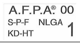 | Alberta Forest Products Association 500—10709 Jasper Avenue Edmonton, Alberta T5J 3N3 www.albertaforestproducts.ca |
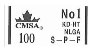 | Canadian Mill Services Association #200, 601—6th Street New Westminster, British Columbia V3L 3C1 www.canserve.org |
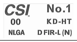 | Canadian Softwood Inspection Agency Inc. 1047—250A Street Aldergrove, British Columbia V4W 2S8 www.canadiansoftwood.com |
 | Central Forest Products Association Inc. c/o Reimer & Co., Chartered Accountants PO Box 146 Swan River, Manitoba R0L 1Z0 www.cfpa-lumber.com |
 | Council of Forest Industries Southern Region: 360—1855 Kirschner Road Kelowna, British Columbia V1Y 4N7 Northern Region: 400—1488 Fourth Avenue Prince George, British Columbia V2L 4Y2 www.cofi.org |
 | MacDonald Inspection Services Ltd. 842 Eland Drive Campbell River, British Columbia V9W 6Y8 www.gradestamp.com |
 | Maritime Lumber Bureau PO Box 459 Amherst, Nova Scotia B4H 4A1 www.mlb.ca |
 | Newfoundland and Labrador Lumber Producers Association c/o Canadian Lumber Standards Accreditation Board P.O. Box 8 Glovertown, Newfoundland A0G 2L0 www.clsab.ca |
 | Northwest Territories Forest Industries Association PO Box 220 Fort Smith, Northwest Territorries X0E 0P0 |
 | Ontario Forest Industries Association (Home of CLA Grading and Inspection) 20 Toronto Street Suite 950 Toronto, Ontario M5C 2B8 www.ofia.com |
 | Ontario Lumber Manufacturers' Association PO Box 97530 Toronto, Ontario M1C 4Z1 www.olma.ca |
 | Pacific Lumber Inspection Bureau 1010 S. 336th Street Suite 300 Federal Way, Washington 98003 USA British Columbia Division: P.O. Box 19118 Fourth Avenue Postal Outlet Vancouver, British Columbia V6C 4R8 www.plib.org |
 | Association Conseil de l’industrie forestière du Québec (Québec Forest Industry Council) 1175, avenue Lavigerie Bureau 200 Sainte Foy, Québec G1V 4P1 www.cifq.com |
A-Table 9.3.2.1. Lumber Grading. Copy linkAdd bookmark
To identify board grades the paragraph number of the NLGA rules under which the lumber is graded must be shown in the grade mark. Paragraph 113 is equivalent to WWPA rules and paragraph 114 is equivalent to WCLIB rules. When graded in accordance with WWPA or WCLIB rules, the grade mark will not contain a paragraph number.
To identify board grades the paragraph number of the NLGA “Standard Grading Rules for Canadian Lumber” under which the lumber is graded must be shown in the grade mark. Paragraph 113 is equivalent to WWPA “Western Lumber Grading Rules 2017” and paragraph 114 is equivalent to WCLIB “Grading Rules for West Coast Lumber”. When graded in accordance with WWPA or WCLIB rules, the grade mark will not contain a paragraph number.
A-9.3.2.8.(1) Non-Standard Lumber. Copy linkAdd bookmark
The NLGA “Standard Grading Rules for Canadian Lumber” permit lumber to be dressed to sizes below the standard sizes (38 x 89 mm (2" x 4"), 38 x 140 mm (2" x 6"), 38 x 184 mm (2" x 8"), etc.) provided the grade stamp shows the reduced size. This Sentence permits the use of the span tables for such lumber, provided the size indicated on the stamp is not less than 95% of the corresponding standard size. Allowable spans in the tables must be reduced a full 5% even if the undersize is less than the 5% permitted.
A.9.3.2.9.(1) Clearances Under Structural Wood Elements for Inspection. Copy linkAdd bookmark
Figure A-9.3.2.9.(1) illustrates clearances under structural wood elements and visibility of supporting elements where required to permit inspection for termite infestation.
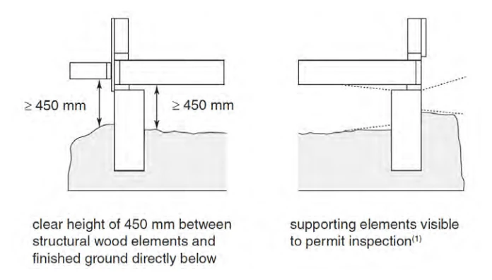
A.9.3.2.9.(3) Protection of Structural Wood Elements from Moisture and Decay. Copy linkAdd bookmark
There are many above-ground, structural wood systems where precipitation is readily trapped or drying is slow, creating conditions conducive to decay. Some examples of elements that can accumulate water when exposed to precipitation if they are not detailed to allow drainage are:
- beams extending beyond roof decks
- junctions between deck members
- connections between balcony guards and walls.
A-9.3.2.9.(4) Protection of Retaining Walls and Cribbing from Decay. Copy linkAdd bookmark
Retaining walls supporting soil are considered to be structural elements of the building if a line drawn from the outer edge of the footing to the bottom of the exposed face of the retaining wall is greater than 45° to the horizontal. Retaining walls supporting soil may be structural elements of the building if the line described above has a lower slope.
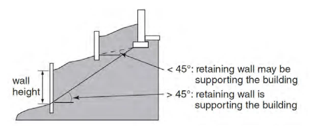
Retaining walls that are not critical to the support of building foundations but are greater than 1.2 m in height may pose a danger of sudden collapse to persons adjacent to the wall if the wood is not adequately protected from decay. The height of the retaining wall or cribbing is measured as the vertical difference between the ground levels on each side of the wall.
A-9.4.1.1. Structural Design. Copy linkAdd bookmark
Article 9.4.1.l. establishes the principle that the structural members of Part 9 buildings must
- comply with the prescriptive requirements provided in Part 9,
- be designed in accordance with accepted good practice, or
- be designed in accordance with Part 4 using the loads and limits on deflection and vibration specified in Part 9 or Part 4.
Usually a combination of approaches is used. For example, even if the snow load calculation on a wood roof truss is based on Subsections 9.4.2., the joints must be designed in accordance with Part 4. Wall framing may comply with the prescriptive requirements in Subsections 9.23.3., 9.23.10., 9.23.11. and 9.23.12., while the floor framing may be engineered.
Design according to Part 4 or accepted good engineering practice, such as that described in the “Engineering Guide for Wood Frame Construction” (2014 CWC Guide), published by the Canadian Wood Council, requires engineering expertise. The CWC Guide contains alternative solutions and provides information on the applicability of the Part 9 prescriptive structural requirements to further assist designers and building officials to identify the appropriate design approach. The need for professional involvement in the structural design of a building, whether to Part 4 or Part 9 requirements or accepted good practice, is defined by provincial legislation and is reflected in Section 1.2. of Division C.
A-9.4.1.1.(3) Structural Design for Lateral Wind and Earthquake Loads. Copy linkAdd bookmark
The only explicit treatment of structural loads in Section 9.4. is for gravity loads; wind and earthquake loads are dealt with implicitly in the body of Part 9 and are not used as inputs to any of the span tables. There may therefore be a tendency to assume that wind and earthquake loads do not need to be considered in the design of Part 9 buildings. In most cases this is true: the majority of low rise, wood frame buildings have a great deal of structural redundancy and continuity and have more than enough capacity to resist lateral loads due to wind and earthquake.
For example, in a traditional house configuration, even if there are large openings in the exterior walls for picture windows and sliding doors, the many interior partitions act as shear walls and provide adequate lateral stability. This may not be the case for some newer house designs.
However, this does not apply to all building configurations or details that might be found in Part 9 buildings. For example, a mercantile building might be long and narrow with almost entirely windowed walls on the ends and few structurally attached interior partitions. See Figure A-9.4.1.1.(3)-A. In such a case, wind and earthquake loads would have to be considered in the design of the long structural walls and their foundations.
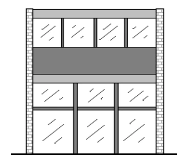
Many buildings have been constructed with the lowest level exterior walls as short, wood-frame knee- or pony-walls. In the past, these were often constructed with no lateral bracing and with no interior partitions. The only structural continuity in the foundation-to-knee-wall and knee-wall- to-floor joints comes from nailing and this is inadequate to resist lateral loads from significant earthquakes. See Figure A-9.4.1.1.(3)-B. These walls must be braced or sheathed to resist lateral loads from earthquakes. In higher load regions, they should be sheathed. In all regions, storeys with knee-walls should be considered as storeys for the purpose of determining building height and the application of the Part 9 structural requirements.
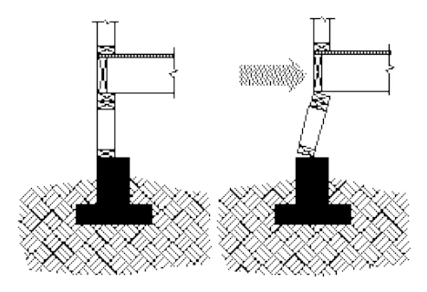
Thus, Part 9 buildings are not exempt from having to comply with the wind and earthquake loading requirements of Part 4. In many cases, these considerations can safely be ignored but, in certain configurations, the building’s resistance to wind and earthquake loads must be carefully considered. See also A-9.23.10.2.
In cases where lateral load design is required, the “Engineering Guide for Wood Frame Construction” (CWC Guide) provides acceptable engineering solutions as an alternative to Part 4. The CWC Guide also contains alternative solutions and provides information on the applicability of the Part 9 prescriptive structural requirements to further assist designers and building officials to identify the appropriate design approach.
A-9.4.2.1.(1) and 9.4.2.2. Application of Simplified Part 9 Snow Loads. Copy linkAdd bookmark
The simplified specified snow loads described in Article 9.4.2.2. may be used where the structure is of the configuration that is typical of traditional wood-frame residential construction and its performance. This places limits on the spacing of joists, rafters and trusses, the spans of these members and supporting members, deflection under load, overall dimensions of the roof and the configuration of the roof. It assumes considerable redundancy in the structure.
Because very large buildings may be constructed under Part 9 by constructing firewalls to break up the building area, it is possible to have Part 9 buildings with very large roofs. The simplified specified snow loads may not be used when the total roof area of the overall structure exceeds 4 550 m2. Thus, the simplified specified snow load calculation may be used for typical townhouse construction but would not be appropriate for much larger commercial or industrial buildings, for example.
The simplified specified snow loads are also not designed to take into account roof configurations that seriously exacerbate snow accumulation. This does not pertain to typical projections above a sloped roof, such as dormers, nor does it pertain to buildings with higher and lower roofs. Although two-level roofs generally lead to drift loading, smaller light-frame buildings constructed according to Part 9 have not failed under these loads. Consequently, the simplified calculation may be used in these cases. Rather, this limitation on application of the simplified calculation pertains to roofs with high parapets or significant other projections above the roof, such as elevator penthouses, mechanical rooms or larger equipment that would effectively collect snow and preclude its blowing off the roof.
The reference to Article 9.4.3.1. invokes, for roof assemblies other than common lumber trusses, the same performance criteria for deflection.
The unit weight of snow on roofs, γ, obtained from measurements at a number of weather stations across Canada varied from about 1.0 to 4.5 kN/m3. An average value for use in design in lieu of better local data is γ = 3.0 kN/m3. In some locations the unit weight of snow may be considerably greater than 3.0 kN/m3. Such locations include regions where the maximum snow load on the roof is reached only after contributions from many snowstorms, coastal regions, and regions where winter rains are considerable and where a unit weight as high as 4.0 kN/m3 may be appropriate.
A-9.4.2.3.(1) Accessible Platforms Subject to Snow and Occupancy Loads. Copy linkAdd bookmark
Many platforms are subject to both occupancy loads and snow loads. These include balconies, decks, verandas, flat roofs over garages and carports. Where such a platform, or a segregated area of such a platform, serves a single dwelling unit, it must be designed for the greater of either the specified snow load or an occupancy load of 1.9 kPa. Where the platform serves more than one single dwelling unit or an occupancy other than a residential occupancy, higher occupancy loads will apply, as specified in Table 4.1.5.3.
A-9.4.2.4.(1) Specified Loads for Attics or Roof Spaces with Limited Accessibility. Copy linkAdd bookmark
Typical residential roofs are framed with roof trusses and the ceiling is insulated.
Residential trusses are placed at 600 mm on centre with web members joining top and bottom chords. Lateral web bracing is installed perpendicular to the span of the trusses. As a result, there is limited room for movement inside the attic or roof space or for storage of material. Access hatches are generally built to the minimum acceptable dimensions, further limiting the size of material that can be moved into the attic or roof space.
With exposed insulation in the attic or roof space, access is not recommended unless protective clothing and breathing apparatus are worn.
Thus, the attic or roof space is recognized as uninhabitable and loading can be based on actual dead load. In emergency situations or for the purpose of inspection, it is possible for a person to access the attic or roof space without over-stressing the truss or causing damaging deflections.
A-Table 9.4.4.1. Classification of Soils. Copy linkAdd bookmark
Sand or gravel may be classified by means of a picket test in which a 38 mm by 38 mm (2" x 2") picket bevelled at the end at 45° to a point is pushed into the soil. Such material is classified as “dense or compact” if a man of average weight cannot push the picket more than 200 mm into the soil and “loose” if the picket penetrates 200 mm or more.
Clay and silt may be classified as “stiff” if it is difficult to indent by thumb pressure, “firm” if it can be indented by moderate thumb pressure, “soft” if it can be easily penetrated by thumb pressure, where this test is carried out on undisturbed soil in the wall of a test pit.
A-9.4.4.4.(1) Soil Movement. Copy linkAdd bookmark
In susceptible soils, changes in temperature or moisture content can cause significant expansion and contraction. Soils containing pyrites can expand simply on exposure to air.
Expansion and Contraction due to MoistureCopy linkAdd bookmark
Clay soils are most prone to expansion and contraction due to moisture. Particularly wet seasons can sufficiently increase the volume of the soil under and around the structure to cause heaving of foundations and floors-on-ground, or cracking of foundation walls. Particularly dry seasons or draw-down of water by fast-growing trees can decrease the volume of the soil supporting foundations and floors-on-ground, thus causing settling.
Frost HeaveCopy linkAdd bookmark
Frost heave is probably the most commonly recognized phenomenon related to freezing soil. Frost heave results when moisture in frost-susceptible soil (clay and silt) under the footings freezes and expands. This mechanism is addressed by requirements in Section 9.12. regarding the depth of excavations.
Ice LensesCopy linkAdd bookmark
When moisture in frost-susceptible soils freezes, it forms an ice lens and reduces the vapour pressure in the soil in the area immediately around the lens. Moisture in the ground redistributes to rebalance the vapour pressures providing more moisture in the area of the ice lens. This moisture freezes to the lens and the cycle repeats itself. As the ice lens grows, it exerts pressure in the direction of heat flow. When lenses form close to foundations and heat flow is toward the foundation - as may be the case with unheated crawl spaces or open concrete block foundations insulated on the interior-the forces may be sufficient to crack the foundation.
AdfreezingCopy linkAdd bookmark
Ice lenses can adhere themselves to cold foundations. Where heat flow is essentially upward, parallel to the foundation, the pressures exerted will tend to lift the foundation. This may cause differential movement or cracking of the foundation. Heat loss through basement foundations of cast-in-place concrete or concrete block insulated on the exterior appears to be sufficient to prevent adfreezing. Care must be taken where the foundation does not enclose heated space or where open block foundations are insulated on the interior. The installation of semi-rigid glass fibre insulation has demonstrated some effectiveness as a separation layer to absorb the adfreezing forces.
PyritesCopy linkAdd bookmark
Pyrite is the most common iron disulphide mineral in rock and has been identified in rock of all types and ages. It is most commonly found in metamorphic and sedimentary rock, and especially in coal and shale deposits.
Weathering of pyritic shale is a chemical-microbiological oxidation process that results in volume increases that can heave foundations and floors-on-ground. Concentrations of as little as 0.l% by weight have caused heaving. Weathering can be initiated simply by exposing the pyritic material to air. Thus, building on soils that contain pyrites in concentrations that will cause damage to the building should be avoided, or measures should be taken to remove the material or seal it. Material containing pyrites should not be used for backfill at foundations or for supporting foundations or floors-on-ground.
Where it is not known if the soil or backfill contains pyritic material in a deleterious concentration, a test is available to identify its presence and concentration.
References:
- (1) Legget, R.F. and Crawford, C.B. Trees and Buildings. Canadian Building Digest 62, Division of Building Research, National Research Council Canada, Ottawa, 1965.
- (2) Hamilton, J.J. Swelling and Shrinking Subsoils. Canadian Building Digest 84, Division of Building Research, National Research Council Canada, Ottawa, 1966.
- (3) Hamilton, J.J. Foundations on Swelling and Shrinking Subsoils. Canadian Building Digest 184, Division of Building Research, National Research Council Canada, Ottawa, 1977.
- (4) Penner, W., Eden, W.J., and Gratten-Bellew, P.E. Expansion of Pyritic Shales. Canadian Building Digest 152, Division of Building Research, National Research Council Canada, Ottawa, 1975.
- (5) Swinton, M.C., Brown, W.C., and Chown, G.A. Controlling the Transfer of Heat, Air and Moisture through the Building Envelope. Small Buildings - Technology in Transition, Building Science Insight '90, Institute for Research in Construction, National Research Council Canada, Ottawa, 1990.
A-9.4.4.6. and A-9.15.1.1. Loads on Foundations. Copy linkAdd bookmark
The prescriptive solutions provided in Part 9 relating to footings and foundation walls only account for the loads imposed by drained earth. Drained earth is assumed to exert a load equivalent to the load that would be exerted by a fluid with a density of 480 kg/m3. The prescriptive solutions do not account for surcharges from saturated soil or additional loads from heavy objects located adjacent to the building. Where such surcharges are expected, the footings and foundation walls must be designed and constructed according to Part 4.
A-9.5.1.2. Combination Rooms. Copy linkAdd bookmark
If a room draws natural light and natural ventilation from another area, the opening between the two areas must be large enough to effectively provide sufficient light and air. This is why a minimum opening of 3 m2 is required, or the equivalent of the area of a set of double doors. The effectiveness of the transfer of light and air also depends on the size of the transfer opening in relation to the size of the dependent room; in measuring the area of the wall separating the two areas, the whole wall on the side of the dependent room should be considered, not taking into account offsets that may be in the surface of the wall.
The opening does not necessarily have to be in the form of a doorway; it may be an opening at eye level. However, if the dependent area is a bedroom, provision must be made for the escape window required by Article 9.9.10.1. to fulfill its safety function. This is why a direct passage is required between the bedroom and the other area; the equivalent of at least a doorway is therefore required for direct passage between the two areas.
A-9.5.2.3.(4) Stud Wall Reinforcement. Copy linkAdd bookmark
This provision for future attachment of grab bars in the main bathroom of a residential occupancy including houses requires the installation of suitable blocking in the stud wall. Sentence 9.31.2.3.(1) specifies the required load resistance. Also, see Appendix Note A-3.3.4.9.(1).
A-9.6.1.2.(2) Mirrored Glass Doors. Copy linkAdd bookmark
Standard CAN/CGSB-82.6-M, “Doors, Mirrored Glass, Sliding or Folding, Wardrobe”, covers mirrored glass doors for use on reach-in closets. It specifies that such doors are not to be used for walk-in closets.
A-9.6.1.3.(2) Maximum Glass Area. Copy linkAdd bookmark
Tables 9.6.1.3.-A to 9.6.1.3.-F are based on CAN/CGSB-12.20-M, “Structural Design of Glass for Buildings”, and the wind load provisions in Article 4.1.7.3. The maximum glass area values given in these Tables are intended to be equal to or smaller than those that would be determined using the standard and wind load provisions directly to design for each individual case.
A-Table 9.6.1.3.-G Glass in Doors. Copy linkAdd bookmark
Maximum areas in Table 9.6.1.3.-G for other than fully tempered glazing are cut off at 1.50 m2, as this would be the practical limit after which safety glass would be required by Sentence 9.6.1.4.(2).
A-9.7.3.2.(1)(a) Minimizing Condensation. Copy linkAdd bookmark
The total prevention of condensation on the surfaces of fenestration products is difficult to achieve and, depending on the design and construction of the window or door, may not be absolutely necessary. Clause 9.7.3.2.(1)(a) therefore requires that condensation be minimized, which means that the amount of moisture that condenses on the inside surface of a window, door or skylight, and the frequency at which this occurs, must be limited. The occurrence of such condensation must be sufficiently rare, the accumulation of any water must be sufficiently small, and drying must be sufficiently rapid to prevent the deterioration of moisture-susceptible materials and the growth of fungi.
A-9.7.4.2.(1) Standards Referenced for Windows, Doors and Skylights. Copy linkAdd bookmark
Canadian Requirements in the Harmonized StandardCopy linkAdd bookmark
In addition to referencing the Canadian Supplement, CSA A440S1, “Canadian Supplement to AAMA/WDMA/CSA 101/I.S.2/A440, “NAFS - North American Fenestration Standard/Specification for Windows, Doors, and Skylights,” the Harmonized Standard, AAMA/WDMA/CSA 101/I.S.2/A440, “NAFS - North American Fenestration Standard/ Specification for Windows, Doors, and Skylights,” contains some Canada-specific test criteria.
Standards Referenced for Excluded ProductsCopy linkAdd bookmark
Clause 1.1, General, of the Harmonized Standard defines the limits to the application of the standard with respect to various types of fenestration products. A list of exceptions to the application statement identifies a number of standards that apply to excluded products. Compliance with those standards is not required by the Code; the references are provided for information purposes only.
Label Indicating Performance and Compliance with StandardCopy linkAdd bookmark
The Canadian Supplement requires that a product’s performance ratings be indicated on a label according to the designation requirements in the Harmonized Standard and that the label include
- design pressure, where applicable,
- negative design pressure, where applicable,
- water penetration test pressure, and
- the Canadian air infiltration and exfiltration levels.
It should be noted that, for a product to carry a label in Canada, it must meet all of the applicable requirements of both the Harmonized Standard and the Canadian Supplement, including the forced entry requirements.
Water Penetration ResistanceCopy linkAdd bookmark
For the various performance grades listed in the Harmonized Standard, the corresponding water penetration resistance test pressures are a percentage of the design pressure. For R-class products, water penetration resistance test pressures are 15% of design pressure. In Ontario, driving rain wind pressures (DRWP) have been determined for the locations listed in MMAH Supplementary Standard SB-1.
To achieve equivalent levels of water penetration resistance for all locations, the Canadian Supplement includes a provision for calculating specified DRWP at the building site considering building exposure. Specified DRWP values are, in some cases, greater than 15% of design pressure and, in other cases, less than 15% of design pressure. For a fenestration product to comply with the Code, it must be able to resist the structural and water penetration loads at the building site. Reliance on a percentage of design pressure for water penetration resistance in the selection of an acceptable fenestration product will not always be adequate. Design pressure values are reported on a secondary designator, which is required by the Canadian Supplement to be affixed to the window. The DRWP given in the Canadian Supplement should be used for all products covered in the scope of the Harmonized Standard.
Uniform Load Structural TestCopy linkAdd bookmark
The Harmonized Standard specifies that fenestration products be tested at 150% of design pressure for wind (specified wind load) and that skylights and roof windows be tested at 200% of design pressure for snow (specified snow load). With the change in the 2006 Building Code to a 1-in-50 return period for wind load, a factor of 1.4 rather than 1.5 is now applied for wind. The Building Code has traditionally applied a factor of 1.5 rather than 2.0 for snow. Incorporating these lower load factors into the Code requirements for fenestration would better reflect acceptable minimum performance levels; however, this has not been done in order to avoid adding complexity to the Code, to recognize the benefits of Canada-US harmonization, and to recognize that differentiation of products that meet the Canadian versus the US requirements would add complexity for manufacturers, designers, specifiers and regulatory officials.
Condensation ResistanceCopy linkAdd bookmark
The Harmonized Standard identifies three test procedures that can be used to determine the condensation resistance of windows and doors. Only the physical test procedure given in CSA A440.2, which is referenced in Table 9.7.3.3., can be used to establish Temperature Index (I) values. Computer simulation tools can also be used to estimate the relative condensation resistance of windows, but these methods employ different expressions of performance known as Condensation Resistance Factors (CR). I and CR values are not interchangeable.
Where removable multiple glazing panels (RMGP) are installed on the inside of a window, care should be taken to hermetically seal the RMGP against the leakage of moisture-laden air from the interior into the cavity on the exterior of the RMGP because the moisture transported by the air could lead to significant condensation on the interior surface of the outside glazing.
Basement WindowsCopy linkAdd bookmark
Clause 12.4.2, Basement Windows, of the Harmonized Standard refers to products that are intended to meet Code requirements for ventilation and emergency egress. The minimum test size of 800 mm x 360 mm (total area of 0.288 m2) specified in the standard will not provide the minimum openable area required by the Code for bedrooms (i.e. 0.35 m2 with no dimension less than 380 mm) and the means to provide minimum open area identified in the standard is inconsistent with the requirements of the Code (see Subsection 9.9.10. for bedroom windows). The minimum test size specified in the standard will also not provide the minimum ventilation area of 0.28 m2 required for non-heating-season natural ventilation (see Article 9.32.2.2.).
Greenhouse WindowsCopy linkAdd bookmark
Greenhouse-type windows feature a sloped, roof-like top portion, which is subjected to the same snow loads as roofs. The Canadian Supplement only applies the snow load calculation to skylights, which do not include greenhouse windows according to the definition for skylights given in the Canadian Supplement and the Harmonized Standard. Where such windows are used, it is recommended that snow loads on the top portion of the window be taken into account.
Performance of Doors: Limited Water Ingress Control.Copy linkAdd bookmark
While the control of precipitation ingress is a performance requirement for exterior doors, side-hinged doors can comply with the referenced standard. AAMA/WDMA/CSA 101/I.S.2/A440, “NAFS – North American Fenestration Standard/ Specification for Windows, Doors, and Skylights”, when tested at a pressure differential of 0 Pa (0.0 psf) or higher, but less than the minimum test pressure required for the indicated performance class and performance grade. Such doors are identified with a “Limited Water” (LW) rating on the product label.
There is no restriction on the use of side-hinged doors having a limited water designation when the tested water penetration resistance of such doors is equal to or greater than the specified Driving Rain Wind Pressure for the building location, as stated in Clause A.4.4 of CSA A440S1, “Canadian Supplement to AAMA/WDMA/CSA 101/I.S.2/A440, NAFS – North American Fenestration Standard/Specification for Windows, Doors, and Skylights”. When an LW door does not have sufficient water penetration resistance for the building location, Clause B.5.3.3 of CSA A440S1 states that these doors should only be used and installed in a protected location, such as under a porch roof. Other protected locations would be behind a storm door, or a door separating conditioned space from unconditioned space, such as in cold storage rooms. The Exposure Nomograph in Annex A of CAN/CSA-A440.4, “Window, Door, and Skylight Installation”, provides an acceptable method to determine whether a door is considered protected, which depends on overhang ratio, and the terrain and moisture index of the building location. A door with an LW rating and a low exposure could provide acceptable water penetration resistance. However, given that the Exposure Nomograph in Annex A of CAN/CSA-A440.4 does not account for the intensity of wind driven rain, a door with an LW rating may not provide appropriate protection in some locations. In such cases, the risk of water penetration may remain the same as if the overhead protection were not provided.
A-9.7.5.2.(1) Forced Entry Via Glazing in Doors and Sidelights. Copy linkAdd bookmark
There is no mandatory requirement that special glass be used in doors or sidelights, primarily because of cost. It is, however, a common method of forced entry to break glass in doors and sidelights to gain access to door hardware and unlock the door from the inside. Although insulated glass provides increased resistance over single glazing, the highest resistance is provided by laminated glass. Tempered glass, while stronger against static loads, is prone to shattering under high, concentrated impact loads.
Laminated glass is more expensive than annealed glass and must be used in greater thicknesses. Figure A-9.7.5.2.(1) shows an insulated sidelight made of one pane of laminated glass and one pane of annealed glass. This method reduces the cost premium that would result if both panes were laminated.
Consideration should be given to using laminated glazing in doors and accompanying sidelights regulated by Article 9.6.1.3., in windows located within 900 mm of locks in such doors, and in basement windows.
Underwriters' Laboratories of Canada have produced ULC-S332, “Standard for Burglary Resisting Glazing Material”, which provides a test procedure to evaluate the resistance of glazing to attacks by thieves. While it is principally intended for plate glass show windows, it may be of value for residential purposes.
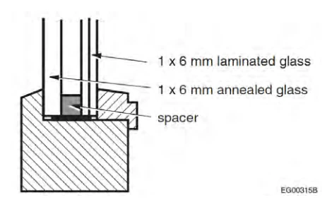
A-9.7.5.2.(2) Resistance of Doors to Forced Entry. Copy linkAdd bookmark
This Sentence designates standard ASTM F476, “Standard Test Methods for Security of Swinging Door Assemblies” as an alternate to compliance with the prescriptive requirements for doors and hardware. The annex to the standard provides four security classifications, with acceptance criteria, depending on the type of building and the crime rate of the area in which it is located. The Building Code has only specified Grade 10, the minimum level. The annex suggests the following guidelines be followed when selecting security levels for door assemblies:
Grade 10:
This is the minimum security level and is quite adequate for single-family residential buildings located in stable, low-crime areas.
Grade 20:
This is the low-medium security level and is designed to provide security for residential buildings located in average crime-rate areas and for apartments in both low and average crime-rate areas.
Grade 30:
This is the medium-high security level and is designed to provide security for residential buildings located in higher than average crime-rate areas or for small commercial buildings in average or low crime-rate areas.
Grade 40:
This is the high security level and is designed for small commercial buildings located in high crime-rate areas. This level could also be used for residential buildings having an exceptionally high incidence of semi-skilled burglary attacks.
All these grades satisfy the Code and can be considered for use where a higher level of security is desired or warranted.
9.7.5.2.(6) Door Fasteners. Copy linkAdd bookmark
The purpose of the requirement for 30 mm screw penetration into solid wood is to prevent the door from being dislodged from the jamb due to impact forces. It is not the intent to prohibit other types of hinges or strikeplates that are specially designed to provide equal or greater protection.
A-9.7.5.2.(8) Hinged Doors. Copy linkAdd bookmark
Methods of satisfying this Sentence include either using non-removable pin hinges or modifying standard hinges by screw fastening a metal pin in a screw hole in one half of the top and bottom hinges. When the door is closed, the projecting portion of the pin engages in the corresponding screw hole in the other half of the hinge and then, even if the hinge pin is taken out, the door cannot be removed.
A-9.7.5.3.(1) Resistance of Windows to Forced Entry. Copy linkAdd bookmark
Although this Sentence only applies to windows within 2 m of adjacent ground level, certain house and site features, such as balconies or canopy roofs, allow for easy access to windows at higher elevations. Consideration should be given to specifying break-in resistant windows in such locations.
This Sentence does not apply to windows that do not serve the interior of the dwelling unit, such as windows to garages, sun rooms or greenhouses, provided connections between these spaces and the dwelling unit are secure.
One method that is often used to improve the resistance of windows to forced entry is the installation of metal “security bars”. However, while many such installations are effective in increasing resistance to forced entry, they may also reduce or eliminate the usefulness of the window as an exit in case of fire or other emergency that prevents use of the normal building exits. Indeed, unless such devices are easily openable from the inside, their installation in some cases would contravene the requirements of Article 9.9.10.1., which requires every bedroom that does not have an exterior door to have at least one window that is large enough and easy enough to open that it can be used as an exit in case of emergency. Thus an acceptable security bar system should be easy to open from the inside while still providing increased resistance to entry from the outside.
A-9.8.3.1. Permitted Stair Configurations. Copy linkAdd bookmark
| Location/Use of Stairs | Configuration of Stair Treads | ||||
|---|---|---|---|---|---|
| Straight Flight with Rectangular Treads | Curved Flight with Tapered Treads | Winders | Flight with a mix of Rectangular Treads and Tapered Treads | Spiral Stairs | |
| Stairs within dwelling units | Permitted(1) | Permitted(2) | Permitted(3) | Permitted(4) | Permitted(5) |
| Public stairs | Permitted(1) | Permitted(6) | Not permitted | Not permitted | Permitted(5) |
| Exit stairs | Permitted(1) | Permitted(6) | Not permitted | Not permitted | Not permitted |
A-9.8.4. Stair Treads. Copy linkAdd bookmark
The Code distinguishes four principal types of stair treads:
- rectangular treads, which are found in straight flights;
- tapered treads are found in curved flights;
- winders are described in Appendix Note A-9.8.4.6.; and
- spiral stairs are described in Appendix Note A-9.8.4.7. See Figure A-9.8.4.-A.
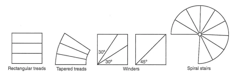
Articles 9.8.4.1. to 9.8.4.8. specify various dimensional limits for steps. Figure A-9.8.4.-B illustrates the elements of a step and how these are to be measured.
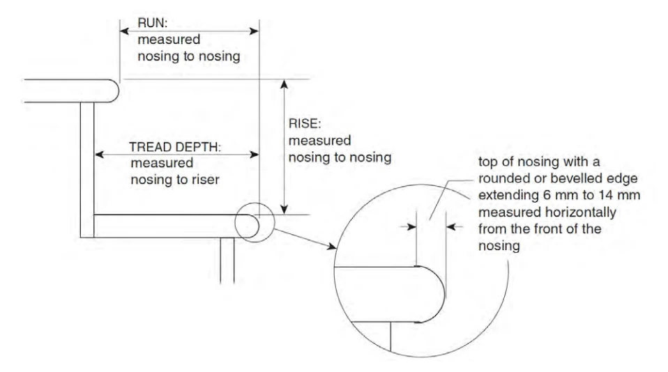
A-9.8.4.6. Winders. Copy linkAdd bookmark
The safest method of incorporating a change in the direction of a stair is to use a landing. Within a dwelling unit, however, where occupants are familiar with their environment, winders are an acceptable method of reducing the amount of floor area devoted to the stair and have not been shown to be more hazardous than a straight run of steps. Nevertheless, care is required to ensure that winders are as safe as possible. Experience has shown that 30° winders are the best compromise and require the least change in the natural gait of the stair user; 45° winders are also acceptable, as they are wider. The Code permits winders to turn through any angle between 30° and 45°, inclusive. This allows winder-type stairs to change direction through any angle between 30° (1 winder) and 90° (2 or 3 winders).
A-9.8.4.7. Spiral Stairs. Copy linkAdd bookmark
A spiral stair is typically described as a stair with a circular plan having uniform treads that radiate from and wind around a common central post or supporting column.
In the context of the Code, the term “spiral stair” is used to describe any stair where:
- a) the plan of the treads forms part or all of the circle,
- b) the maximum stair width and tread depth are less than those required for curved stairs, and
- c) the maximum riser height is greater than that permitted in all other stair configurations.
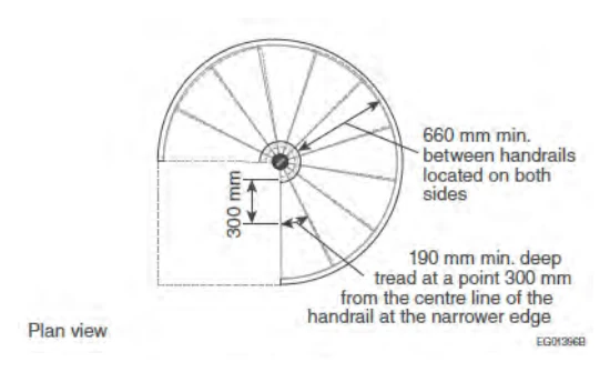
A-9.8.4.8. Tread Nosings. Copy linkAdd bookmark
A sloped or bevelled edge on tread nosings will make the tread more visible through light modelling. The sloped portion of the nosing must not be too wide so as to reduce the risk of slipping of the foot. See Figure A-9.8.4.-B.
A-9.8.6.2.(2) Exemption from Required Landing at Top of Stairs. Copy linkAdd bookmark
A door that swings away from a stair exposes sufficient floor space to act as a landing for users before descending the stairs.
A-9.8.7.1.(2) Wider Stairs than Required. Copy linkAdd bookmark
The intent of Sentence 9.8.7.1.(2) is that handrails be installed in relation to the required exit width only, regardless of the actual width of the stair and ramp. The required handrails are provided along the assumed natural path of travel to and from the building.
A-9.8.7.2. Continuity of Handrails. Copy linkAdd bookmark
The guidance and support provided by handrails is particularly important at the beginning and end of ramps and flights of stairs and at changes in direction such as at landings and winders.
The intent of the requirement in Sentence (2) for handrails to be continuous throughout the length of the stair is that the handrail be continuous from the bottom riser to the top riser of the stair. (See Figure A-9.8.7.2.)
For stairs or ramps serving a single dwelling unit, the intent of the requirement for handrails to be continuous throughout the length of the flight is that the handrail be continuous from the bottom riser to the top riser of the flight. The required handrail may start back from the bottom riser only if it is supported by a newel post or volute installed on the bottom tread. (See Figure A-9.8.7.2.) With regard to stairs serving a house or an individual dwelling unit, the handrail may terminate at landings.
In the case of stairs within dwelling units that incorporate winders, the handrail should be configured so that it will in fact provide guidance and support to the stair user throughout the turn through the winder.
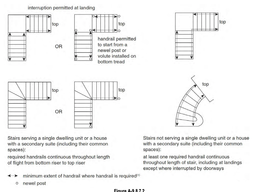
Notes to Figure A-9.8.7.2.:
A-9.8.7.3.(1) Termination of Handrails. Copy linkAdd bookmark
Handrails are required to be installed so as not to obstruct pedestrian travel. To achieve this end, the rail should not extend so far into a hallway as to reduce the clear width of the hallway to less than the required width. Where the stair terminates in a room or other space, likely paths of travel through that room or space should be assessed to ensure that any projection of the handrail beyond the end of the stair will not interfere with pedestrian travel. As extensions of handrails beyond the first and last riser are not required in dwelling units [See Sentence 9.8.7.3.(2)] and as occupants of dwellings are generally familiar with their surroundings, the design of dwellings would not generally be affected by this requirement.
Handrails are also required to terminate in a manner that will not create a safety hazard to blind or visually impaired persons, children whose heads may be at the same height as the end of the rail, or persons wearing loose clothing or carrying items that might catch on the end of the rail. One approach to reducing potential hazards is returning the handrail to a wall, floor or post. Again, within dwelling units, where occupants are generally familiar with their surroundings, returning the handrail to a wall, floor or post may not be necessary. For example, where the handrail is fastened to a wall and does not project past the wall into a hallway or other space, a reasonable degree of safety is assumed to be provided; other alternatives may provide an equivalent level of protection.
A-9.8.7.3.(2) Handrail Extensions. Copy linkAdd bookmark
As noted in Appendix Note A-9.8.7.2., the guidance and support provided by handrails is particularly important at the beginning and end of ramps and flights of stairs and at changes in direction. The extended handrail provides guidance and allows users to steady themselves upon entering or leaving a ramp or flight of stairs. Such extensions are particularly useful to visually-impaired persons, and persons with physical disabilities or who are encumbered in their use of the stairs or ramp.
A-9.8.7.4. Height of Handrails. Copy linkAdd bookmark
Figure A-9.8.7.4. illustrates how to measure handrail height.
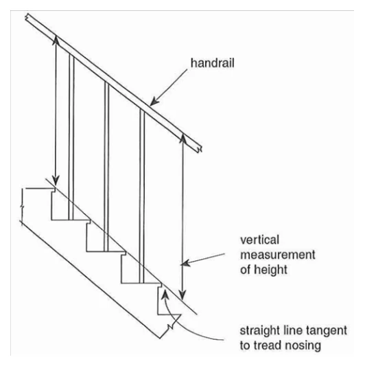
A-9.8.7.5.(2) Handrail Sections. Copy linkAdd bookmark
Handrails are intended to provide guidance and support to stair users. To fulfil this intent, handrails must be “graspable”.
The graspable portion of a handrail should allow a person to comfortably and firmly grab hold by allowing their fingers and thumb to curl under part or all of the handrail. Where the configuration or dimensions of the handrail do not allow a person’s fingers and thumb to reach the bottom of it, recesses that are sufficiently wide and deep to accommodate a person’s fingers and thumb must be provided on both sides of the handrail, at the bottom of the graspable portion, which must not have sharp edges.
A-9.8.7.7. Attachment of Handrails. Copy linkAdd bookmark
Handrails are intended to provide guidance and support to the stair user and to arrest falls. The loads on handrails may therefore be considerable. The attachment of handrails serving a house or an individual dwelling unit may be accepted on the basis of experience, structural design, or the prescriptive requirements of Sentence 9.8.7.7.(2).
A-9.8.8.1. Required Guards. Copy linkAdd bookmark
The requirements relating to guards stated in Part 9 are based on the premise that, wherever there is a difference in elevation of 600 mm or more between two floors, or between a floor or other surface to which access is provided for other than maintenance purposes and the next lower surface, the risk of injury in a fall from the higher surface is sufficient to warrant the installation of some kind of barrier to reduce the chances of such a fall. A wall along the edge of the higher surface will obviously prevent such a fall, provided the wall is sufficiently strong that a person cannot fall through it. Where there is no wall, a guard must be installed. Because guards clearly provide less protection than walls, additional requirements apply to guards to ensure that a minimum level of protection is provided. These relate to the characteristics described in Appendix Notes A-9.8.8.3., A-9.8.8.5.(1) and (2), A-9.8.8.5.(3) and A-9.8.8.6.(1).
Examples of such surfaces where the difference in elevation could exceed 600 mm and consequently where guards would be required include, but are not limited to, landings, porches, balconies, mezzanines, galleries, and raised walkways. Especially in exterior settings, surfaces adjacent to walking surfaces, stairs or ramps often are not parallel to the walking surface or the surface of the treads or ramps. Consequently, the walking surface, stair or ramp may need protection in some locations but not in others. (See Figure A-9.8.8.1.) In some instances, grades are artificially raised close to walking surfaces, stairs or ramps to avoid installing guards. This provides little or no protection for the users. That is why the requirements specify differences in elevation not only immediately adjacent to the construction but also for a distance of 1 200 mm from it by requiring that the slope of the ground be within certain limits. (See Figure A-9.8.8.1.)
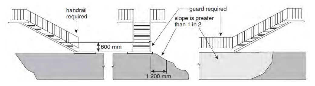
A-9.8.8.1.(4) Window fall Prevention. Copy linkAdd bookmark
The primary intent of the requirement is to minimize the likelihood of small children falling significant heights from open windows. Reflecting reported cases, the requirement applies to openable windows in dwelling units and generally those located on the second floor or higher of residential or mixed-use buildings.
Once cracked open, some openable windows can be opened further by simply pushing on the openable part of the window. Care must be taken in selecting windows, as some with special operating hardware can still be opened further by simply pushing on the window or by deactivating a spring-loaded button or other mechanism that is not considered a window opening control device (WOCD) that could be inadvertently operated by a young child. A technical description of WOCDs can be found in ASTM F2090, “Standard Specification for Window Fall Prevention Devices With Emergency Escape (Egress) Release Mechanisms.”
Examples of WOCDs that can limit window openings to a maximum of 100 mm as required by Clause 9.8.8.1.(4)(b) include, but are not limited to, a fixed-stop lever, a fixed-length cable and a fixed-position stop block. It is important to note that rotary opening mechanisms cannot limit window openings to 100 mm as required by Clause 9.8.8.1.(4)(b) and that windows with such mechanisms cannot act as guards as required by Clause 9.8.8.1.(4)(a), even when the crank handle is removed. Similarly, awning windows with scissor hardware may not keep the window from swinging open once it is unlatched. Hopper windows would be affected only if an opening is created at the bottom as well as at the top of the window. The requirement will impact primarily on the use of sliding windows which do not incorporate devices in their construction that can be used to limit the openable area of the window.
The 100 mm opening limit stated in Sentence 9.8.8.1.(4) is recognized as the maximum opening size required to protect small children from falling through open windows. The minimum 900 mm height of the openable portion of windows required by Sentence 9.8.8.1.(5) corresponds to the minimum height of guards required by Sentence 9.8.8.3.(2) as a means of fall protection in residential occupancies.
A-9.8.8.2. Loads on Guards. Copy linkAdd bookmark
Guards must be constructed so as to be strong enough to protect persons from falling under normal use. Many guards installed in dwelling units or on exterior stairs serving one or two dwelling units have demonstrated acceptable performance over time. The loading specified in the first row of Table 9.8.8.2. is intended to be consistent with the performance provided by these guards. Guards constructed in accordance with MMAH Supplementary Standard SB-7 are deemed to meet the requirements of Article 9.8.8.2.
The load on guards within dwelling units, or on exterior guards serving not more than two dwelling units, is to be imposed over an area of the guard such that, where standard balusters are used and installed at the maximum 100 mm spacing permitted for required guards, 3 balusters will be engaged. Where the balusters are wider, only two may be engaged unless they are spaced closer together. Where the guard is not required, and balusters are installed more than 100 mm apart, fewer balusters may be required to carry the imposed load.
A-9.8.8.3. Minimum Heights. Copy linkAdd bookmark
Guard heights are generally based on the waist heights of average persons. Generally, lower heights are permitted in dwelling units because the occupants become familiar with the potential hazards, and situations which lead to pushing and jostling under crowded conditions are less likely to arise.
A-9.8.8.5.(1) and (3) Risk of Falling Through Guards. Copy linkAdd bookmark
The risk of falling through a guard is especially prevalent for children. Therefore, the requirements are stringent for guards in all buildings except industrial buildings, where children are unlikely to be present except under strict supervision.
A-9.8.8.5.(4) Risk of Children Getting Their Heads Lodged Between Balusters. Copy linkAdd bookmark
The requirements to prevent children falling through guards also serve to provide adequate protection against this problem. However, guards are often installed where they are not required by the Code; i.e., in places where the difference in elevation is less than 600 mm. In these cases, there is no need to require the openings between balusters to be less than 100 mm. However, there is a range of openings between 100 mm and 200 mm in which children can get their heads stuck. Therefore, openings in this range are not permitted except in buildings of industrial occupancy, where children are unlikely to be present except under strict supervision.
A-9.8.8.6.(1) Risk of Children Climbing Over Guards. Copy linkAdd bookmark
Guards are sometimes constructed with horizontal or near-horizontal members between balusters such that a ladder effect is achieved. This can be very tempting for young children to climb, thus exposing themselves to risk of falling over the guard. Such construction is not permitted for required guards in buildings of residential occupancy.
A-9.8.9.6. Finish for Treads, Landings and Ramps. Copy linkAdd bookmark
A tactile indicator strip signals a warning to people with no or low vision that they are approaching a change in level. The strip is set back from the leading edge of the stair to provide sufficient warning of the change in level in advance. Also, see Appendix Note A-3.4.6.1.(2).
A-9.9.4.5.(1) Openings in Exterior Walls of Exits. Copy linkAdd bookmark
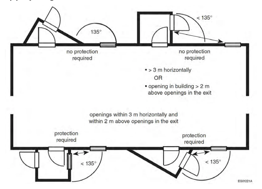
A-9.9.8.4.(1) Independent and Remote Exits. Copy linkAdd bookmark
Subsection 9.9.8. requires that some floor areas have more than one exit. The intent is to ensure that, if one exit is made untenable or inaccessible by a fire, or its exterior door is blocked by an exterior incident, one or more other exits will be available to permit the occupants to escape. However, if the exits are close together, all exits might be made untenable or inaccessible by the same fire. Sentence 9.9.8.4.(1), therefore, requires at least two of the exits to be located remotely from each other. This is not a problem in many buildings falling under Part 9. For instance, apartment buildings usually have exits located at either end of long corridors. However, in other types of buildings (e.g., dormitory and college residence buildings) this is often difficult to accomplish and problems arise in interpreting the meaning of the word “remote”. Article 3.4.2.3. is more specific, generally requiring the distance between exits to be one half the diagonal dimension of the floor area or at least 9 m. However, it is felt that such criteria would be too restrictive to impose on the design of all the smaller buildings which are governed by Part 9. Nevertheless, the exits should be placed as far apart as possible and the Part 3 criteria should be used as a target. Designs in which the exits are so close together that they will obviously both become contaminated in the event of a fire are not acceptable.
A-9.9.10.1.(1) Bedroom Window Opening Areas and Dimensions. Copy linkAdd bookmark
Although the minimum opening dimensions required for height and width are 380 mm, a window opening that is 380 mm by 380 mm would not comply with the minimum area requirements. (See Figure A-9.9.10.1.(1))
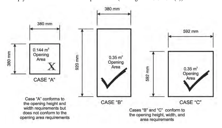
A-9.9.10.1.(2) Bedroom Window Height. Copy linkAdd bookmark
Sentence 9.9.10.1.(2) requires every floor level which contains a bedroom to have at least one window or door to the exterior that is large enough and easy enough to open that it can be used as an exit in case of a fire. However, Article 9.9.10.1. does not set a maximum sill height for such a window in a basement area. It is recommended that the sills of windows intended for use as emergency exits from basement bedroom areas be not higher than 1.5 m above the floor. Sometimes it is difficult to avoid having the sill higher than this; e.g., skylights, windows in basement bedrooms. In these cases, it is recommended that access to the window be improved by some means such as built-in furniture installed below the window. (See Figure A-9.9.10.1.(2))
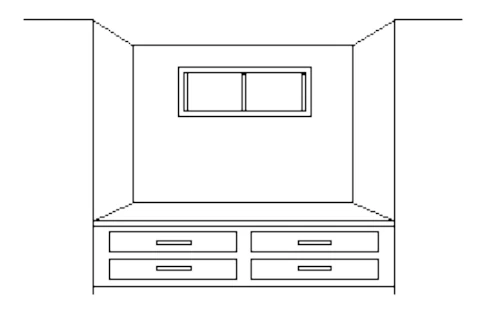
A-9.9.10.1.(3) Window Opening into a Window Well. Copy linkAdd bookmark
Sentence 9.9.10.1.(3) specifies that there must be a minimum clearance of 550 mm in front of designated escape windows to allow persons to escape a basement bedroom in an emergency. This specified minimum clearance is consistent with the minimum required width for means of egress from a floor area (see Article 9.9.5.5.) and the minimum required width for path of travel on exit stairs (see Article 9.9.6.1.). It is considered the smallest acceptable clearance between the escape window and the facing wall of the window well that can accommodate persons trying to escape a bedroom in an emergency given that they are not moving straight through the window but must move outward and up, and must have sufficient space to change body orientation.
Once this clearance is provided, no additional clearance is needed for windows with sliders, casements, or inward-opening awnings. However, for windows with outward-opening awnings, additional clearance is needed to provide the required 550 mm beyond the outer edge of the sash. (See Figure A-9.9.10.1.(3))
Depending on the likelihood of snow accumulation in the window well, it could be difficult — if not impossible — to escape in an emergency. The window well should be designed to provide sufficient clear space for a person to get out the window and then out the well, taking into account potential snow accumulation.
Hopper windows (bottom-hinged operators) should not be used as escape windows in cases where the occupants would be required to climb over the glass.
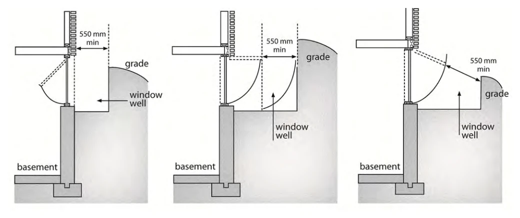
A-9.9.11.5.(1)(e) Colour Contrast. Copy linkAdd bookmark
The identification of floors and other signs intended to facilitate orientation for persons with vision loss should offer maximum colour contrast to be effective. For this reason, it is recommended that white on black or black on white be used, as this combination produces the best legibility. It is also recommended that the sign surfaces be processed to prevent glare.
A-9.10.1.3.(8) and (9) Installation of Sprinkler, Standpipe and Hose Systems. Copy linkAdd bookmark
Some provisions captured by the cross-reference to Part 3 go beyond the intended application of the cross-reference.
In the context of the cross-reference, Subsections Articles 3.2.5.8 to 3.2.5.15., 3.2.5.17. and 3.2.5.18. apply only where sprinkler, standpipe or hose systems are installed in a Part 9 building, whether the installation is voluntary or for the purpose of complying with the provisions in Part 9. Provisions in Part 3 that identify buildings or spaces in which these systems are to be installed do not apply.
A-9.10.1.4.(1) Commercial Cooking Equipment. Copy linkAdd bookmark
Part 6 refers to NFPA 96, “Standard for Ventilation Control and Fire Protection of Commercial Cooking Operations”, which in turn references “Commercial Cooking Equipment”. However, the deciding factor as to whether or not NFPA 96 applies is the potential for production of grease-laden vapours and smoke, rather than the type of equipment used. While NFPA 96 does not apply to domestic equipment for normal residential family use, it should apply to domestic equipment used in commercial, industrial, institutional and similar cooking applications where the potential for the production of smoke and grease-laden vapours exceeds that for normal residential family use.
A-9.10.3.1.(1) Fire and Sound Resistance of Building Assemblies. Copy linkAdd bookmark
The Tables found in MMAH Supplementary Standard SB-3 may be used to select building assemblies for compliance with Article 9.10.3.1. and Subsection 9.11.2. Assembles not listed in those Tables are equally acceptable provided their fire and sound resistance can be demonstrated to meet the above-noted requirements on the basis of tests referred to in 9.10.3.1. and 9.11.1. or by using the data in MMAH Supplementary Standard SB-2.
A-9.10.4.1.(4) Mezzanines Not Considered as Storeys. Copy linkAdd bookmark
Mezzanines increase the occupant load and the fire load of the storey of which they are part. To take the added occupant load into account for the purpose of evaluating other requirements that are dependent on this criteria, their floor area is added to the floor area of the storey.
A-9.10.8.3.(2) Light-Frame Construction. Copy linkAdd bookmark
Light-frame walls, columns, arches and beams do not include heavy timber elements or masonry or concrete construction.
A-9.10.9.2.(2) and (3) Continuity of Smoke-Tight Barrier. Copy linkAdd bookmark
The continuity of a smoke-tight barrier where it abuts another smoke-tight barrier, a floor, a ceiling or a wall assembly is maintained by constructing smoke-tight joints (e.g., through the design of the gypsum board joints and framing members) or by filling all openings at the juncture of the assemblies with a material that will ensure the integrity of the smoke-tight barrier at that location.
A-9.10.9.6.(1) Penetration of Fire Separations. Copy linkAdd bookmark
Sentence 9.10.9.6.(1), like Article 3.1.9.1., is intended to ensure that the integrity of fire separations is maintained where they are penetrated by various types of service equipment.
For buildings regulated by Part 3, firestop materials used to seal openings around building services, such as pipes, ducts and electrical outlet boxes, must meet a minimum level of performance demonstrated by standard test criteria.
A similar approach is applied to buildings regulated by Part 9 when complying with Clause 9.10.9.6.(1)(a). In addition, because of the type of construction normally used for Part 9 buildings, it is assumed that the requirement to maintain the integrity of the fire separation is satisfied by the use of generic firestop materials such as mineral wool, gypsum plaster or Portland cement mortar to seal penetrations in accordance with Clause 9.10.9.6.(1)(c).
The use of the terms “tightly fitted” and “cast in place” in Clause 9.10.9.6.(1)(b) is intended to emphasize that there are to be no gaps between the building service or penetrating item and the membrane or assembly it penetrates.
A-9.10.9.8.(1) Large Recessed Outlet Boxes. Copy linkAdd bookmark
Outlet boxes that exceed the area limits specified in Sentence 9.10.9.8.(2) or (3) do not need to be sealed at the penetration by a firestop in accordance with Sentence 9.10.9.8.(1) if they are installed in a recessed enclosure with a construction that maintains the continuity of the fire-resistance rating of the fire separation or membrane. Any penetrations of the enclosure by wiring or cables must comply with all applicable requirements.
A-9.10.9.8.(3)(a)(i) Separating Enclosures. Copy linkAdd bookmark
The fire block material separating the outlet box from the adjacent space within the assembly should span the framing members such that all four sides and the back of the outlet box are enclosed by a membrane or framing member conforming to Article 9.10.16.3. Any penetrations of the enclosure by wiring or cables must comply with all applicable requirements. (See also Note A-3.1.11.7.(7))
A-9.10.9.18.(4) Separation Between Dwelling Units and Garages. Copy linkAdd bookmark
The gas-tight barrier between a dwelling unit and an attached garage is intended to provide reasonable protection from carbon monoxide and gasoline fumes entering the dwelling unit. Construction assemblies incorporating an air barrier system will perform adequately with respect to gas tightness, provided reasonable care is exercised where the wall or ceiling is pierced by building services. Where a garage is open to the adjacent attic space above the dwelling unit it serves, a gas-tight barrier in the dwelling unit ceiling will also provide protection. Unit masonry walls forming the separation between a dwelling unit and an adjacent garage should be provided with two coats of sealer or plaster or covered with gypsum wallboard on the side of the wall exposed to the garage. All joints must be sealed to ensure continuity of the barrier. (See also Sentences 9.25.3.3.(3) to (8))
A-9.10.12.4.(1) Protection of Overhang of Common Roof Space. Copy linkAdd bookmark
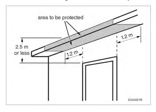
A-9.10.12.4.(3) Protection at Soffits. Copy linkAdd bookmark
The materials required by this Sentence to be used as protection for soffit spaces in certain locations do not necessarily have to be the finish materials. They can be installed either behind the finishes chosen for the soffits or in lieu of these.
A-9.10.13.2.(1) Wood Doors in Fire Separations. Copy linkAdd bookmark
CAN/ULC-S113, “Standard Specification for Wood Core Doors Meeting the Performance Required by CAN/ULC-S104 for Twenty Minute Fire Rated Closure Assemblies” provides construction details to enable manufacturers to build wood core doors that will provide a 20 min fire-protection rating without the need for testing. The Standard requires each door to be marked with
- (1) manufacturer’s or vendor’s name or identifying symbol,
- (2) the words “Fire Door”, and
- (3) a reference to the fire-protection rating of 20 min.
A-9.10.14.5.(1) Minor Combustible Cladding Elements. Copy linkAdd bookmark
Minor elements of cladding that is required to be noncombustible are permitted to be of combustible material, provided they are distributed over the building face and not concentrated in one area. Examples of minor combustible cladding elements include door and window trim and some decorative elements.
A-9.10.15.1.(1) Application of Subsection 9.10.15. Copy linkAdd bookmark
Subsection 9.10.15. applies to the spatial separation between houses which may contain one dwelling unit above another. The designer has the option of using either Subsection 9.10.14. or Subsection 9.10.15. for the determination of spatial separation requirements for these types of buildings. However, the requirements of these two Subsections cannot be mixed.
The buildings to which Subsection 9.10.15. applies include:
- traditional individual detached houses with or without a secondary suite,
- semi-detached houses (doubles) where each house may contain a secondary suite,
- row houses, where any house may contain a secondary suite (see Sentence 9.10.11.2.(1)), and
- stacked dwelling units where one of them is a secondary suite.
Subsection 9.10.15. does not apply to stacked row houses/townhouses or stacked dwelling units that are not within a house with a secondary suite.
A-9.10.15.4.(2) Staggered or Skewed Exposing Building Faces of Houses. Copy linkAdd bookmark
Studies at the National Fire Laboratory of the National Research Council have shown that, where an exposing building face is stepped back from the property line or is at an angle to the property line, it is possible to increase the percentage of glazing in those portions of the exposing building face further from the property line without increasing the amount of radiated energy that would reach the property line in the event of a fire in such a building. Figures A-9.10.15.4.(2)-A to A-9.10.15.4.(2)-C show how Sentences 9.10.15.4.(1) and (2) and 9.10.15.5.(2) could be applied to exposing building faces that are stepped back from or not parallel to the property line.
The following procedure can be used to establish the maximum permitted area of glazed openings for such facades:
- Calculate the total area of the exposing building face, i.e. facade of the fire compartment, as described in the definition of exposing building face.
- Identify the portions into which the exposing building face is to be divided. It can be divided in any number of portions, not necessarily of equal size.
- Measure the limiting distance for each portion. The limiting distance is measured along a line perpendicular to the wall surface from the point closest to the property line.
- Establish the line in Table 9.10.15.4. from which the maximum permitted percentage area of glazed openings will be read. The selection of the line depends on the maximum area of exposing building face for the whole fire compartment, including all portions, as determined in Step 1.
- On that line, read the maximum percentage area of glazed openings permitted in each portion of the exposing building face according to the limiting distance for that portion.
- Calculate the maximum area of glazed openings permitted in each portion. The area is calculated from the percentage found applied to the area of that portion.
Table 9.10.15.4. is used to determine the maximum area of glazed openings. Therefore, unglazed portions of doors need not be counted, as for other types of buildings.
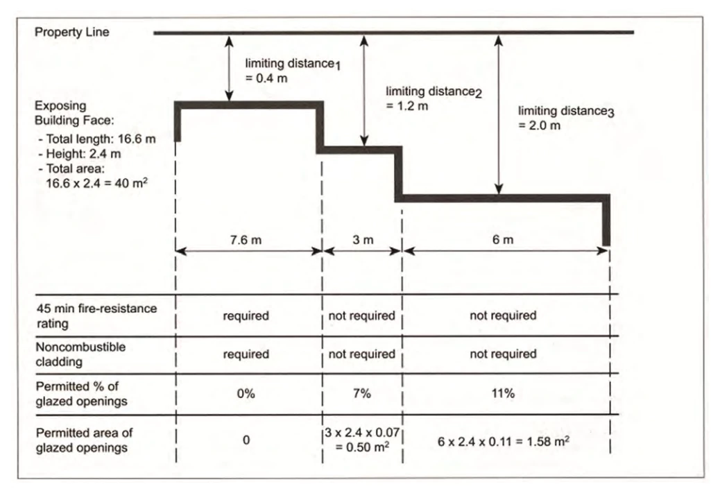
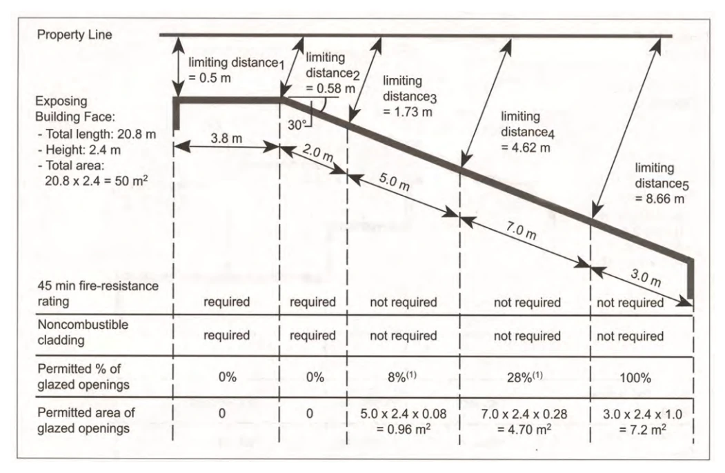
Note to Figure A-9.10.15.4.(2)-B:
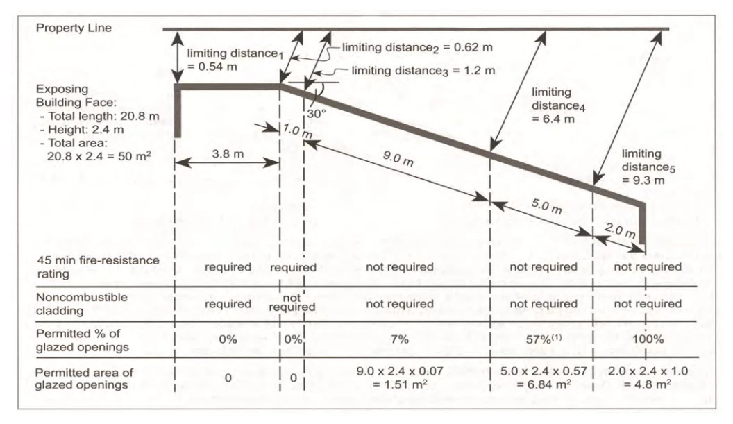
Note to Figure A-9.10.15.4.(2)-C:
A-9.10.18.3.(1) Fire Alarm, Fire Detection and Smoke Detection Devices and Systems. Copy linkAdd bookmark
A number of provisions captured by the cross-reference to Subsection 3.2.4. address issues already addressed in Subsection 9.10.18. and so are not applicable to Part 9 buildings. For example, Articles 9.10.18.2. and 9.10.18.8. identify the Part 9 buildings where fire alarm systems are required, so Article 3.2.4.1. does not apply.
Note that, because the cross-reference relating to sprinkler systems in Sentence 9.10.1.3.(8) refers to conformance with Articles 3.2.5.12. to 3.2.5.15. and Article 3.2.5.17., the requirements of Subsection 3.2.4. regarding electrical supervision and monitoring do not normally apply to sprinkler systems in Part 9 buildings. However, where a sprinkler system is installed in lieu of heat and smoke detectors according to Sentence 9.10.18.4.(3) electrical supervision and monitoring of the sprinkler system must comply with the provisions in Subsection 3.2.4.
A-9.10.19.1. and A-9.10.19.3. Smoke Alarms with Visual Signalling Component. Copy linkAdd bookmark
Smoke alarms with a visual signalling component can alert people who are deaf, deafened or hard of hearing to the presence of smoke in the dwelling just as the alarm sound provides an alert to people with no or low vision or who are sighted. The visual signal provides an extra level of safety alerts to building residents.
A-9.10.19.3.(1) Location of Smoke Alarms. Copy linkAdd bookmark
Statistics have shown that next to kitchen fires, fires originating in bedrooms within dwelling units account for the second highest causes of fire deaths in homes.
The requirement for smoke alarms in sleeping rooms (bedrooms) provides early detection and warning of fires originating in sleeping rooms. Smoke alarms located outside sleeping rooms are required as they are better capable of detecting a fire originating outside of the room.
A smoke alarm is not required on each level in a split-level dwelling unit as each level does not count as a separate storey. Determine the number of storeys in a split-level dwelling unit and which levels are part of which storey as follows:
- establish grade, (See definition of “grade” in Sentence 1.4.1.2.(1) of Division A.);
- identify the first storey, (See definition of “first storey” in Sentence 1.4.1.2.(1) of Division A.);
- identify the basement, (See definition of “basement” in Sentence 1.4.1.2.(1) of Division A.);
- identify the second storey and, where applicable, the third storey.
Additional Smoke Alarms Outside of Sleeping AreasCopy linkAdd bookmark
As a minimum, one smoke alarm is required to be installed on each storey, preferably on the upper level of each one. As noted above, however, when the dwelling unit contains more than one sleeping area, a smoke alarm must be installed to serve each area. Where the sleeping areas are on two levels of a single storey in a split-level dwelling unit, an additional smoke alarm must be installed so that both areas are protected. See Figure A-9.10.19.3.(1).
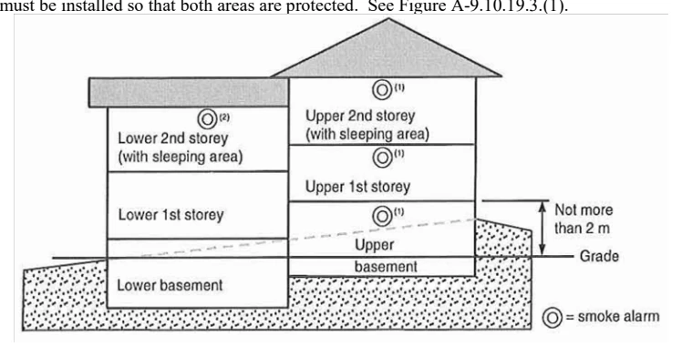
Notes to Figure A-9.10.19.3.(1):
A-9.10.19.5.(2) Interconnection of Smoke Alarms. Copy linkAdd bookmark
Electrical regulations may require that separate power sources be provided for smoke alarms in the main dwelling unit and the secondary suite where the units have separate electrical services. In these situations, interconnection of smoke alarms between the units can be achieved through wireless communication.
A-9.10.20.3.(1) Fire Department Access Route Modification. Copy linkAdd bookmark
In addition to other considerations taken into account in the planning of fire department access routes, special variations could be permitted for a house or residential building that is protected with an automatic sprinkler system. The sprinkler system must be designed in accordance with the appropriate NFPA standard and there must be assurance that water supply pressure and quantity are unlikely to fail. These considerations could apply to buildings that are located on the sides of hills and are not conveniently accessible by roads designed for firefighting equipment and also to infill housing units that are located behind other buildings on a given property.
A-9.10.22. Clearances from Gas, Propane and Electric Cooktops. Copy linkAdd bookmark
The Electrical Safety Code adopted under Ontario Regulation 164/99 (Electrical Safety Code), and Ontario Natural Gas Code address clearances directly above, in front of, behind and beside ranges. Where side clearances are zero, the standards do not address clearances to building elements located both above the level of the range elements or burners and to the side of the appliance. Through reference to the Electrical Safety Code adopted under Ontario Regulation 164/99 (Electrical Safety Code) and the requirements in Articles 9.10.22.2. and 9.10.22.3., the Building Code addresses all clearances. Where clearances are addressed by the Building Code and the Electrical Safety Code adopted under Ontario Regulation 164/99 (Electrical Safety Code) or Ontario Natural Gas Code, conformance with all relevant criteria is achieved by compliance with the most stringent criteria.
Installation of Microwave Ovens Over CooktopsCopy linkAdd bookmark
The minimum vertical clearances stated in Article 9.10.22.2. apply only to combustible framing, finishes and cabinets. They do not apply to microwave ovens installed over cooktops nor to range hoods. Microwave ovens must comply with CAN/CSA-C22.2 NO. 150, “Microwave Ovens”, which is referenced in the Electrical Safety Code adopted under Ontario Regulation 164/99 (Electrical Safety Code). This standard includes tests to confirm that the appliance will not present a hazard when installed according to the manufacturer’s instructions.
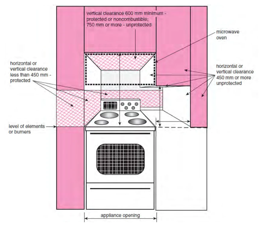
A-9.11. Sound Transmission. Copy linkAdd bookmark
Airborne SoundCopy linkAdd bookmark
Airborne sound is transmitted between adjoining spaces directly through the separating wall, floor and ceiling assemblies and via the junctions between these separating assemblies and the flanking assemblies.
The Sound Transmission Class (STC) rating describes the performance of the separating wall or floor/ceiling assembly, whereas the Apparent Sound Transmission Class (ASTC) takes into consideration the performance of the separating element as well as the flanking transmission paths. Therefore, from the occupants’ point of view, the best indicator of noise protection between the two spaces is the ASTC rating.
As a key principle, it is important to follow a “whole system” approach when designing or constructing assemblies that separate dwelling units because the overall sound performance of walls and floors is also influenced by fire protection measures and the structural design of the assemblies. Likewise, changes to the construction of assemblies to meet sound transmission requirements may have fire and structural implications. Another key principle is that enhancing the performance of the separating element does not automatically enhance the system’s performance.
For horizontally adjoining spaces, the separating assembly is the intervening wall and the pertinent flanking surfaces include those of the floor, ceiling, and side wall assemblies that have junctions with the separating wall assembly, normally at its four edges. For each of these junctions, there are a set of sound transmission paths. Figure A-9.11.-A illustrates the horizontal sound transmission paths at the junction of a separating wall with flanking floor assemblies.
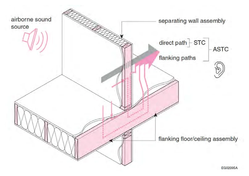
For vertically adjoining spaces, the separating assembly is the intervening floor/ceiling and the pertinent flanking surfaces include those of the side wall assemblies in the upper and lower rooms that have junctions with the separating floor/ceiling assembly at its edges, of which there are normally four. For each of these junctions, there is a set of sound transmission paths. Figure A-9.11.-B illustrates the vertical sound transmission paths at the junction of a separating floor/ceiling assembly with two flanking wall assemblies.
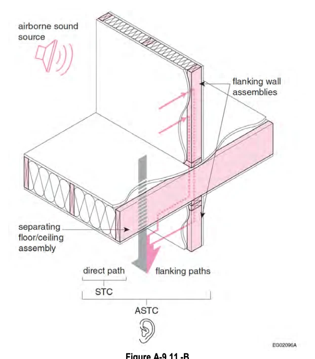
Control of Sound LeaksCopy linkAdd bookmark
The metrics used to characterize the sound transmission performance of assemblies separating dwelling units do not account for the adverse effects of air leaks in those assemblies, which can transfer sound. Sound leaks can occur where a wall meets another wall, the floor, or the ceiling. They can also occur where the wall finish is cut for the installation of equipment or services. The following are examples of measures for controlling sound leaks:
- Avoid back-to-back electrical outlets or medicine cabinets;
- Carefully seal cracks or openings so structures are effectively airtight;
- Apply sealant below the plates in stud walls, between the bottom of gypsum board sheets and the structure behind, around all penetrations for services and, in general, wherever there is a crack, a hole or the possibility of one developing;
- Include sound-absorbing material inside the wall if not already required.
The reduction of air leakage is also addressed to some extent by the smoke tightness requirements in the Code.
The NRC report entitled “Best Practice Guide on Fire Stops and Fire Blocks and their Impact on Sound Transmission,” provides additional information regarding the possible impacts of fire protection measures on sound transmission.
The calculation of and laboratory testing for STC and ASTC ratings are performed on intact assemblies having no penetrations or doors. When measuring ASTC ratings in the field, openings can be blocked with insulation and drywall.
To verify that the required acoustical performance is being achieved, a field test can be done at an early stage in the construction; ASTM E336, “Standard Test Method for Measurement of Airborne Sound Attenuation Between Rooms in
Buildings” gives a complete measurement. A simpler and less expensive method is presented in ASTM E597, “Practice for Determining a Single Number Rating of Airborne Sound Insulation for Use in Multi-Unit Building Specifications”. The rating derived from this test is usually within 2 points of the STC obtained from ASTM E336. It is useful for verifying performance and finding problems during construction. Alterations can then be made prior to project completion.
Impact NoiseCopy linkAdd bookmark
Section 9.11. has no requirements for control of impact noise transmission. Footstep and other impacts can cause severe annoyance in multi-family residences. Builders concerned about quality and reducing occupant complaints will ensure that floors are designed to minimize impact transmission. A recommended criterion is that bare floors (tested without a carpet) should achieve an impact insulation class (IIC) of 55. Some lightweight floors that satisfy this requirement may still cause complaints about low frequency impact noise transmission. Adding carpet to a floor will always increase the IIC rating but will not necessarily reduce low frequency noise transmission. Good footstep noise rejection requires fairly heavy floor slabs or floating floors.
Most frequently used methods of test for impact noise are ASTM E492, “Standard Test Method for Laboratory Measurement of Impact Sound Transmission Through Floor-Ceiling Assemblies Using The Tapping Machine”, or ASTM E1007, “Standard Test Method for Field Measurement of Tapping Machine Impact Sound Transmission Through Floor-Ceiling Assemblies and Associated Support Structures”.
Machinery NoiseCopy linkAdd bookmark
Elevators, garbage chutes, plumbing, fans, and heat pumps are common sources of noise in buildings. To reduce annoyance from these, they should be placed as far as possible from sensitive areas. Vibrating parts should be isolated from the building structure using resilient materials such as neoprene or rubber.
A-9.11.1.3.(2)(b) Control of Airborne Noise in Buildings. Copy linkAdd bookmark
Tables 1 and 2 of MMAH Supplementary Standard SB-3, “Fire and Sound Resistance Tables” present separating assemblies that comply with Subsection 9.11. However, selecting an appropriate separating assembly is only one part of the solution for reducing airborne sound transmission between adjoining spaces. To fully address the sound performance of the whole system, flanking assemblies must be connected to the separating assembly in accordance with Article 9.11.1.4.
A-9.11.1.4. Adjoining Construction. Copy linkAdd bookmark
Tables A-9.11.1.4.-A to A-9.11.1.4.-D present generic options for the design and construction of junctions between separating and flanking assemblies. Constructing according to these options is likely to meet or exceed an ASTC rating of 47. Other designs may be equally acceptable if their sound resistance can be demonstrated to meet the minimum ASTC rating or better on the basis of tests referred to in Article 9.11.1.2., or if they comply with Subsection 5.8.1. However, some caution should be applied when designing solutions that go beyond the options provided in these Tables: for example, adding more material to a wall could negatively impact its sound performance or have no effect at all.
Table A-9.11.1.4.-A presents compliance options for the construction of separating wall assemblies with flanking floor, ceiling and wall assemblies in horizontally adjoining spaces.
Table A-9.11.1.4.-B presents options for improving the sound performance of separating wall systems beyond that achieved by implementing the options presented in Table A-9.11.1.4.-A. The suggested performance improvement options are listed in order of approximate acoustic priority and are interdependent, i.e., if options at the top of the list are not implemented, then options at the bottom of the list will have much lesser effect.
Table A-9.11.1.4.-C presents compliance options for the construction of separating floor/ceiling assemblies with flanking wall assemblies in vertically adjoining spaces.
Table A-9.11.1.4.-D presents options for improving the sound performance of separating floor/ceiling assemblies beyond that achieved by implementing the options presented in Table A-9.11.1.4.-C. The suggested performance improvement options are listed in order of approximate acoustic priority and are interdependent, i.e., if options at the top of the list are not implemented, then options at the bottom of the list will have much lesser effect.
| Type of Separating Wall Assembly with STC ≥ 50 from Table 1 of MMAH Supplementary Standard SB-3 | Options for Design and Construction of Junctions and Flanking Surfaces(1) to Address Horizontal Sound Transmission Paths | ||
|---|---|---|---|
| Bottom Junction (between separating wall and flanking floors) | Top Junction (between separating wall and flanking ceiling) | Side Junctions (between separating wall and flanking walls) | |
| W4, W5, W6 (single stud) W8, W9, W10, W11, W12 (staggered studs) |
|
|
|
Example Showing Side View of Bottom and Top Junctions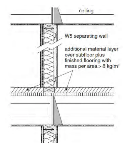 | Example Showing Plan View of Side Junctions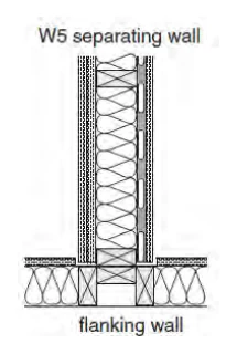 | ||
Example Showing Side View of Bottom and Top Junctions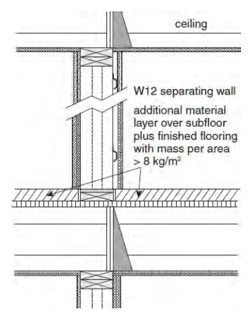 | Example Showing Plan View of Side Junctions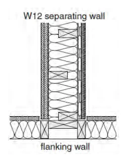 | ||
| W13, W14, W15 |
|
|
|
Example Showing Side View of Bottom and Top Junctions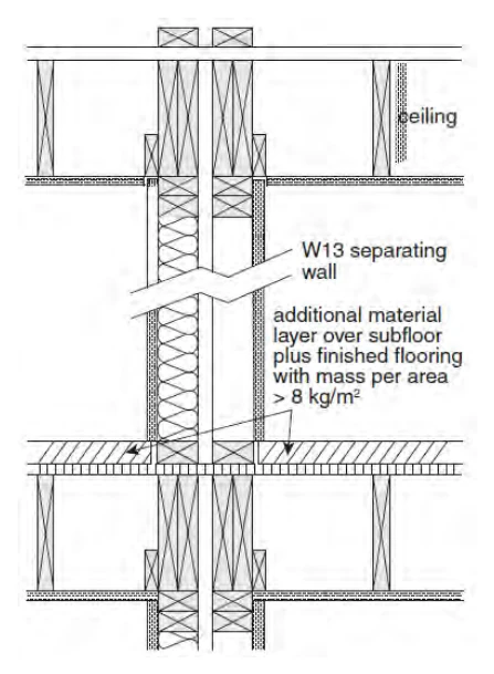 | Example Showing Plan View of Side Junctions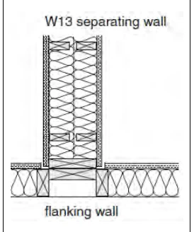 | ||
| S1 to S15 |
|
|
|
Example Showing Side View of Bottom and Top Junctions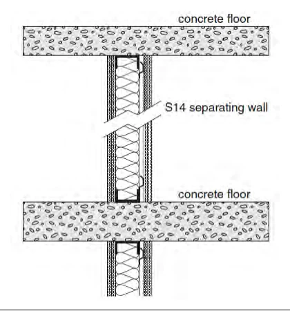 | Example Showing Plan View of Side Junctions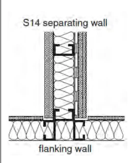 | ||
| B1 to B10 |
|
|
|
Example Showing Side View of Bottom and Top Junctions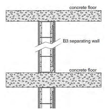 | Examples Showing Plan View of Side Junctions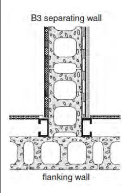 | ||
Notes to Table A-9.11.1.4.-A:
| Type of Separating Wall Assembly with STC ≥ 50 from Table 1 of MMAH Supplementary Standard SB-3 | Performance Improvement Options for Junctions Between Separating Walls and Flanking Floor/Ceiling Assemblies |
|---|---|
| W4, W5, W6, W8, W9, W10, W11, W12 |
|
| W13, W14, W15 |
|
| S1 to S15 |
|
| B1 to B10 |
|
Notes to Table A-9.11.1.4.-B:
| Type of Separating Floor/Ceiling Assembly with STC ≥ 50 from Table 2 of MMAH Supplementary Standard SB-3 | Options for Design and Construction of Junctions and Flanking Surfaces(1) to Address Vertical Sound Transmission Paths | |
|---|---|---|
| Junctions with Flanking Steel-Framed Walls | Junctions with Flanking Concrete Walls | |
| F1 (with or without gypsum board ceiling) |
|
|
Examples Showing Side View of Junctions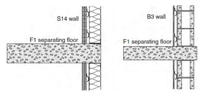 | ||
| F8 to F38 | Junctions with Flanking Loadbearing or Non-Loadbearing Walls | |
| ||
Example Showing Side View of Junctions in Flanking Loadbearing Wall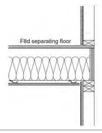 | Example Showing Side View of Junctions in Flanking Non-Loadbearing Wall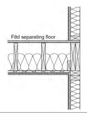 | |
Notes to Table A-9.11.1.4.-C:
| Type of Separating Floor Assembly with STC ≥ 50 from Table 2 of MMAH Supplementary Standard SB-3 | Performance Improvement Options for Junctions Between Separating Floors and Flanking Wall Assemblies |
|---|---|
| F1 (with or without gypsum board ceiling) |
|
| F8 to F38 |
|
Notes to Table A-9.11.1.4.-D:
A-Table 9.11.1.4. Floor Treatments. Copy linkAdd bookmark
The sound insulation performance of lightweight framed floors can be improved by adding floor treatments, i.e., additional layers of material over the subfloor (e.g. concrete topping, OSB or plywood) and finished flooring or coverings (e.g., carpet, engineered wood). Table A-Table 9.11.1.4. presents the mass per area values based on thickness and density of a number of generic floor treatment materials (the values for proprietary products may be different; consult the manufacturer’s current data sheets for their products’ values).
| Floor Treatment Material | Thickness, mm | Density, kg/m³ | Mass per Area, kg/m2 |
|---|---|---|---|
| Materials Typically Having a Mass per Area Less than 8 kg/m² | |||
| Medium-density fibreboard (MDF) | 2.9 – 6.1 | 790 – 810 | 2.3 – 5.0 |
| Plywood – generic softwood | 12.5 – 13.3 15.5 – 16.3 | 450 – 500 | 5.6 – 6.6 7.0 – 8.1 |
| Ceramic tile | 8.4 | 700 – 1 000 | 5.9 – 8.4 |
| Materials Typically Having a Mass per Area Greater than 8 kg/m² but Less than 16 kg/m² | |||
| Particleboard | 11.3 – 19.2 | 710 – 755 | 8.1 – 14.5 |
| Medium-density fibreboard (MDF) | 13.9 – 21.1 | 640 – 755 | 8.9 – 15.9 |
| Oriented strandboard (OSB) | 14.3 – 15.8 17.3 – 18.8 | 600 – 680 | 8.6 – 10.7 10.4 – 12.8 |
| Plywood – generic softwood | 25.5 | 450 – 500 | 11.5 – 13.1 |
| Materials Typically Having a Mass per Area Greater than 16 kg/m² but Less than 32 kg/m² | |||
| Medium-density fibreboard (MDF) | 25.0 – 32.1 | 640 – 740 | 16.0 – 23.7 |
| Materials Typically Having a Mass per Area Greater than 32 kg/m² | |||
| Concrete | 40.0 – 50.0 | 2 015 – 2 380 | 80.6 – 119.0 |
| Gypsum concrete | 25.0 | 1 840 – 1 870 | 46.1 – 46.7 |
A-Table 9.12.2.2. Minimum Depths of Foundations. Copy linkAdd bookmark
The requirements for clay soils or soils not clearly defined are intended to apply to those soils that are subject to significant volume changes with changes in moisture content.
A-9.12.2.2.(2) Depth and Insulation of Foundations. Copy linkAdd bookmark
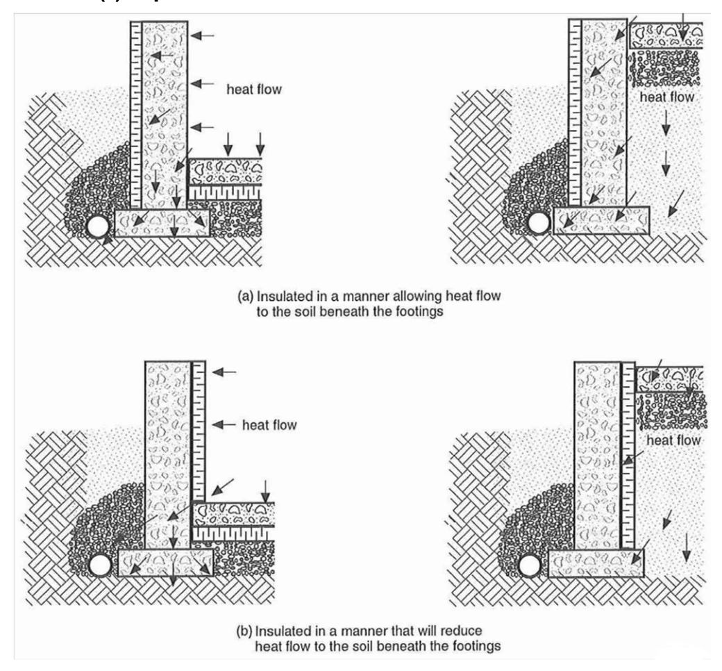
A-9.12.3.3.(1) Deleterious Material in Backfill. Copy linkAdd bookmark
The deleterious debris referred to in this provision includes, but is not limited to:
- organic material and other material subject to decomposition and compaction, which could have an adverse effect on grading around the building,
- materials that will off-gas and have the potential to pose a health hazard, and
- materials that are incompatible with materials used in the foundations, footings, drainage materials or components, or other elements of the building whose required performance would be adversely affected.
A-9.13.2.5. Protection of Interior Finishes from Moisture. Copy linkAdd bookmark
Excess water from cast-in-place concrete and ground moisture tends to migrate toward interior spaces, particularly in the spring and summer. Where moisture-susceptible materials, such as finishes or wood members, are in contact with the foundation wall, the moisture needs to be controlled by installing a moisture barrier on the interior surface of the foundation wall that extends from the underside of the interior finish up the face of the wall to a point just above the level of the ground outside.
The reason the moisture barrier on the interior surface of the foundation wall must be terminated near ground level is to allow any moisture that finds its way into the finished wall cavity from the interior space (through leaks in the air or vapour barrier) to diffuse to the exterior. If the vapour permeance of dampproofing membranes or coatings exceeds 170 ng/(Pa·s·m2), such moisture barriers may be carried full height; if their vapour permeance is less than that, this moisture risks being trapped on the interior surface of the moisture barriers. The permeance limit corresponds to the lower limit for breather-type membranes, such as asphalt-impregnated sheathing paper.
Some insulation products can also be used to protect interior finishes from the effects of moisture. They have shown acceptable performance when applied over the entire foundation wall because, in this case, they also provide vapour barrier and moisture barrier functions and possibly also the air barrier function. Where a single product provides all these functions, there is no risk of trapping moisture between two functional barriers with low water vapour permeance.
A-9.13.2.6.(1) Polyethylene Under Slabs-on-Ground. Copy linkAdd bookmark
Finishing a concrete slab placed directly on polyethylene can, in many cases, cause problems for the inexperienced finisher. A rule of finishing, whether concrete is placed on polyethylene or not, is to never finish or “work” the surface of the slab while bleed water is present or before all the bleed water has risen to the surface and evaporated. If finishing operations are performed too early, such as before all the bleed water has risen and evaporated, surface defects such as blisters, crazing, scaling and dusting can result. This is often the case with slabs placed directly on polyethylene. The amount of bleed water that may come to the surface and the time required for this to happen is increased from that of a slab placed on a compacted granular base. The excess water in the mix from the bottom portion of the slab cannot bleed downward and out of the slab and be absorbed into the granular material below, because of the polyethylene. Therefore, all bleed water, including that from the bottom of the slab, must now rise through the slab to the surface. Quite often in such cases, finishing operations are begun too soon and surface defects result.
One solution that is often suggested is to place a layer of sand between the polyethylene and the concrete. However, this is not an acceptable solution for the following reason: it is unlikely that the polyethylene will survive the slab pouring process entirely intact. Nevertheless, the polyethylene will still be effective in retarding the flow of soil gas if it is in intimate contact with the concrete; soil gas will only be able to penetrate where a break in the polyethylene coincides with a crack in the concrete. The majority of concrete cracks will probably be underlain by intact polyethylene. On the other hand, if there is an intervening layer of a porous medium, such as sand, soil gas will be able to travel laterally from a break in the polyethylene to the nearest crack in the concrete and the total system will be much less resistant to soil gas penetration.
To reduce and/or control the cracking of concrete slabs, it is necessary to understand the nature and causes of volume changes of concrete and in particular those relating to drying shrinkage. The total amount of water in a mix is by far the largest contributor to the amount of drying shrinkage and resulting potential cracking that may be expected from a given concrete. The less total amount of water in the mix, the less volume change (due to evaporation of water), which means the less drying shrinkage that will occur. To lessen the volume change and potential cracking due to drying shrinkage, a mix with the lowest total amount of water that is practicable should always be used. To lower the water content of a mix, superplasticizers are often used to provide the needed workability of the concrete during the placing operation. High water/cementing materials ratio concretes usually have high water content mixes. They should be avoided to minimize drying shrinkage and cracking of the slab. The water/cementing materials ratio for slabs-on-ground should be no higher than 0.55.
A-9.13.4. Exclusion of Soil Gas. Copy linkAdd bookmark
Outdoor air entering a dwelling through above-grade leaks in the building envelope normally improves the indoor air quality in the dwelling by reducing the concentrations of pollutants and water vapour. It is only undesirable because it cannot be controlled. On the other hand, air entering a dwelling through below-grade leaks in the envelope may increase the water vapour content of the indoor air and may also bring in a number of pollutants which it picks up from the soil. This mixture of air, water vapour and pollutants is sometimes referred to as “soil gas”. One pollutant often found in soil gas is radon.
Sentence 9.13.4.2.(1), which requires the installation of an air barrier system, addresses the protection from all soil gases, while the remainder of Article 9.13.4.2. along with Article 9.13.4.3., which require the provision of the means to depressurize the space between the air barrier and the ground, specifically address the capability to mitigate high radon concentrations in the future, should this become necessary.
Radon is a colourless, odourless, radioactive gas that occurs naturally as a result of the decay of radium. It is found to varying degrees as a component of soil gas in all regions of Canada and is known to enter dwelling units by infiltration into basements and crawl spaces. The presence of the decay products of radon in sufficient quantity can lead to increased risk of lung cancer.
The potential for high levels of radon infiltration is very difficult to evaluate prior to construction and thus a radon problem may only become apparent once the building is completed and occupied. MMAH Supplementary Standard SB-9 requires the application of certain radon exclusion measures in dwellings where methane or radon gasses are known to be a problem.
The principal method of resisting the ingress of all soil gases, a resistance which is required for all buildings (see Sentence 9.13.4.2.(1)), is to seal the interface between the soil and the occupied space, so far as is reasonably practicable. Sections 9.18. and 9.25. contain requirements for air and soil gas barriers in assemblies in contact with ground, including those in crawl spaces. Providing control joints to reduce cracking of foundation walls and airtight covers for sump pits (see Section 9.14.) are other measures that can help achieve this objective. The requirements provided in Subsection 9.25.3. are explained in Appendix Notes A-9.25.3.4. and 9.25.3.6. and A-9.25.3.6.(2) and (3).
The principal method of excluding radon is to ensure that the pressure difference across the ground space interface is positive (i.e., towards the outside) so that the inward flow of radon through any remaining leaks will be minimized. The requirements provided in Article 9.13.4.3. are explained in Appendix Note A-9.13.4.3.
A-9.13.4.2.(3) Exception for Buildings Occupied for a Few Hours a Day. Copy linkAdd bookmark
The criterion used by Health Canada to establish the guideline for acceptable radon concentration is the time that occupants spend inside buildings. Health Canada recommends installing a means for the future removal of radon in buildings that are occupied by persons for more than 4 hours per day. Sentence 9.13.4.2.(3) may therefore not apply to buildings or portions of buildings that are intended to be occupied for less than 4 hours a day. Addressing a radon problem in such buildings in the future, should that become necessary, can also be achieved by providing a means for increased ventilation at times when these buildings are occupied.
A-9.13.4.3. Rough-in for a Subfloor Depressurization System. Copy linkAdd bookmark
Providing Performance Criteria for the Depressurization of the Space Between the Air Barrier and the GroundCopy linkAdd bookmark
Article 9.13.4.3. contains two sets of requirements: Sentence (2) describes the criteria for subfloor depressurization systems using performance-oriented language, while Sentence (3) describes one particular acceptable solution using more prescriptive language.
In some cases, subfloor depressurization requires a solution other than the one described in Sentence (3), for example, where compactable fill is installed under slab-on-grade construction.
Completion of a Subfloor Depressurization SystemCopy linkAdd bookmark
The completion of a subfloor depressurization system may be necessary to reduce the radon concentration to a level below the guideline specified by Health Canada.
Further information on protection from radon ingress can be found in the following Health Canada publications:
- “Radon: A Guide for Canadian Homeowners” (CMHC/HC), and
- “Guide for Radon Measurements in Residential Dwellings (Homes).”
A-9.13.4.3.(2)(b) and (3)(b)(i) Effective Depressurization. Copy linkAdd bookmark
To allow effective depressurization of the space between the air barrier and the ground, the extraction opening (the pipe) should not be blocked and should be arranged such that air can be extracted from the entire space between the air barrier and the ground. This will ensure that the extraction system can maintain negative pressure underneath the entire floor (or in heated crawl spaces underneath the air barrier). The arrangement and location of the extraction system inlet(s) may have design implications where the footing layout separates part of the space underneath the floor.
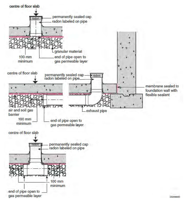
A-9.14.2.1.(1.1) Insulation Applied to the Exterior of Foundation Walls. Copy linkAdd bookmark
In addition to the prevention of heat loss, some types of mineral fibre insulation, such as rigid glass fibre, are installed on the exterior of basement walls for the purpose of moisture control. This is sometimes used instead of crushed rock as a drainage layer between the basement wall and the surrounding soil in order to facilitate the drainage of soil moisture. Water drained by this drainage layer must be carried away from the foundation by the footing drains or the granular drainage layer in order to prevent it from developing hydro-static pressure against the wall. Provision must be made to permit the drainage of this water either by extending the insulation or crushed rock to the drain or by the installation of granular material connecting the two. The installation of such drainage layer does not eliminate the need for normal waterproofing or dampproofing of walls as specified in Section 9.13.
A-9.15.1.1. Application of Footing and Foundation Requirements to Decks and Similar Structures. Copy linkAdd bookmark
Decks, balconies, verandas and similar platforms that are attached to a building or that have an area greater than 10 m2 are, by definition, considered as buildings or parts of buildings. Consequently, they are subject to the requirements in Section 9.15.
A-9.15.1.1.(1)(c) and A-9.20.1.1.(1)(b) Flat Insulating Concrete Form Walls. Copy linkAdd bookmark
Insulating concrete form (ICF) walls are concrete walls that are cast into polystyrene forms, which remain in place after the concrete has cured. Flat ICF walls are solid ICF walls where the concrete is of uniform thickness over the height and width of the wall.
A-9.15.2.4.(1) Preserved Wood Foundations - Design Assumptions. Copy linkAdd bookmark
Tabular data and figures in CSA S406, “Specification of permanent wood foundations for housing and small buildings,” are based upon the general principles provided in CSA O86, “Engineering design in wood” with the following assumptions:
- soil bearing capacity: 75 kPa or more,
- clear spans for floors: 5 m or less,
- floor loadings: 1.9 kPa for first floor and suspended floor, and 1.4 kPa for second storey floor,
- foundation wall heights: 2.4 for slab floor foundation, 3.0 m for suspended wood floor foundation,
- top of granular layer to top of suspended wood floor: 600 mm,
- lateral load from soil pressure: equivalent to fluid pressure of 4.7 kPa per metre of depth,
- ground snow load: 3 kPa,
- basic snow load coefficient: 0.6,
- roof loads are carried to the exterior wall,
- dead loads: roof 0.50 kPa floor 0.47 kPa wall (with siding) 0.32 kPa wall (with masonry veneer) 1.94 kPa foundation wall 0.27 kPa partitions 0.20 kPa
A-9.15.3.4.(2) Footing Sizes. Copy linkAdd bookmark
The footing sizes in Table 9.15.3.4. are based on typical construction consisting of a roof, not more than 3 storeys, and centre bearing walls or beams. For this reason, Clause 9.15.3.3.(1)(b) stipulates a maximum supported joist span of 4.9 m.
It has become common to use flat wood trusses or wood I-joists to span greater distances in floors of small buildings. Where these spans exceed 4.9 m, minimum footing sizes may be based on the following method:
- (a) Determine for each storey the span of joists that will be supported on a given footing. Sum these lengths (sum1).
- (b) Determine the product of the number of storeys times 4.9 m (sum2).
- (c) Determine the ratio of sum1, to sum2.
- (d) Multiply this ratio by the minimum footing sizes in Table 9.15.3.4. to get the required minimum footing size.
Example: A 2-storey house is built using wood I-joists spanning 6 m.
- (a) sum1 = 6 + 6 = 12 m
- (b) sum2 = 4.9 x 2 = 9.8 m
- (c) ratio suml/sum2 = 12/9.8 = 1.22
- (d) required minimum footing size = 1.22 x 350 mm (minimum footing size provided in Table 9.15.3.4.) = 427 mm.
A-Table 9.15.4.2.-A Flat Insulating Concrete Form Walls as Foundation Walls. Copy linkAdd bookmark
Article 9.15.4.2. allows insulating concrete forms (ICFs) to be used to form both laterally supported and laterally unsupported flat, plain (unreinforced) concrete foundation walls intended to support wood-frame walls, floors and roofs under the conditions stipulated in Table 9.15.4.2.-A. Where the limits stated in the Table are exceeded, or where the ICF foundation wall is intended to support one or two storeys of concrete walls formed with flat wall ICFs above ground, Article 9.15.4.5. applies.
A-9.16.4.3.(1) Thickness. Copy linkAdd bookmark
Depressions and ridges often develop at the soil surface or granular base from construction activity prior to the placement of a concrete slab. Allowances for such irregularities in the base must be recognized. A maximum tolerance of -10 mm is permitted provided the minimum slab thickness at any point is not less than 65 mm and the mean thickness of the concrete slab (exclusive of topping) is 75 mm, as shown in Figure A-9.16.4.3.(1).
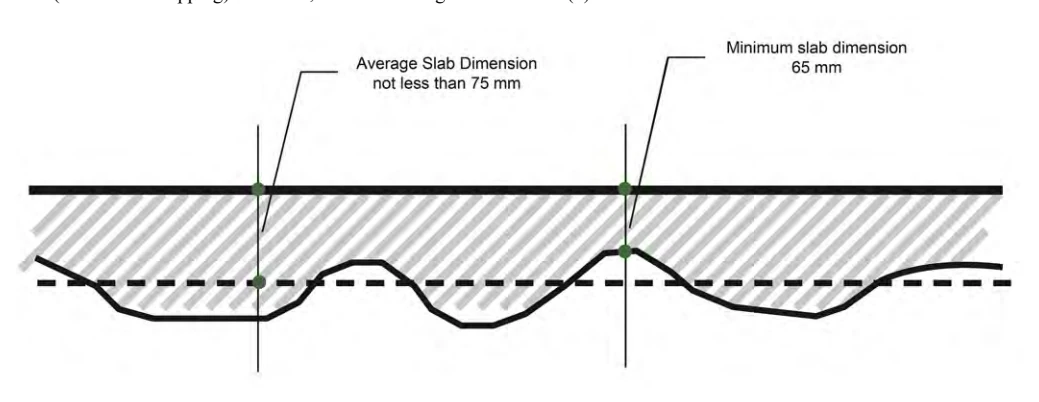
A-9.17.2.2.(2) Lateral Support of Columns. Copy linkAdd bookmark
Because the Building Code does not provide prescriptive criteria to describe the minimum required lateral support, structures are limited to those that have demonstrated effective performance over time and those that are designed according to Part 4. Verandas on early 20th century homes provide one example of structures whose floor and roof are typically tied to the rest of the building to provide effective lateral support. Large decks set on tall columns, however, are likely to require additional lateral support even where they are connected to the building on one side.
A-9.17.3.4. Design of Steel Columns. Copy linkAdd bookmark
The permitted live floor loads of 2.4 kPa and the spans described for steel beams, wood beams and floor joists are such that the load on columns could exceed 36 kN, the maximum allowable load on columns prescribed in CAN/CGSB-7.2, “Adjustable Steel Columns”. In the context of Part 9, loads on columns are calculated from the supported area times the live load per unit area, using the supported length of joists and beams. The supported length is half of the joist spans on each side of the beam and half the beam span on each side of the column.
Dead load is not included based on the assumption that the maximum live load will not be applied over the whole floor. Designs according to Part 4 must consider all applied loads.
A-9.18.7.1.(3) and (4) Protection of Ground Cover in Warm Air Plenums. Copy linkAdd bookmark
The purpose of the requirement is to protect combustible ground cover from smoldering cigarette butts that may drop through air registers. The protective material should extend beyond the opening of the register and have up-turned edges, as a butt may be deflected sideways as it falls.
A-9.19.1.1.(1) Venting of Attic and Roof Spaces. Copy linkAdd bookmark
Controlling the flow of moisture by air leakage and vapour diffusion into roof and attic spaces is necessary to limit moisture-induced deterioration. Given that imperfections normally exist in the vapour barriers and air barrier systems, recent research indicates that venting of roof and attic spaces is generally still required. The exception provided in Article 9.19.1.1. recognizes that some specialized ceiling-roof assemblies, such as those used in some factory-built buildings, have, over time, demonstrated that their construction is sufficiently tight to prevent excessive moisture accumulation. In these cases, ventilation would not be required.
A-9.19.2.1.(1) Access to Attic or Roof Space. Copy linkAdd bookmark
The term “open space” refers to the space between the insulation and the roof sheathing. Sentence 9.19.2.1.(1) requires the installation of an access hatch where the open space in the attic or roof is large enough to allow visual inspection. Although the dimensions of an uninsulated attic or roof space may meet the size that triggers the requirement for an access hatch to be installed, most of that space will actually be filled with insulation and may therefore not be easily inspected, particularly in smaller buildings or under low-sloped roofs.
A-9.19.2.1.(2) Attic Access Openings. Copy linkAdd bookmark
The dimensions for attic access as provided for in the Building Code are minimum dimensions. Where a fuel fired appliance is to be located in the attic, a larger attic access opening shall be provided in conformance with the Gas Utilization Code or other applicable installation code.
A-9.20.1.2. Seismic Zones. Copy linkAdd bookmark
Information on seismic zones for various localities can be found in MMAH Supplementary Standard SB-1.
A-9.20.5.1.(1) Masonry Support. Copy linkAdd bookmark
Masonry veneer must be supported on a stable structure in order to avoid cracking of the masonry due to differential movement relative to parts of the support. Wood framing is not normally used as a support for the weight of masonry veneer because of its shrinkage characteristics. Where the weight of masonry veneer is supported on a wood structure, as is the case for the preserved wood foundations referred to in Sentence 9.20.5.1.(1) for example, measures must be taken to ensure that any differential movement that may be harmful to the performance of masonry is minimized or accommodated. The general principle stated in Article 9.4.1.1., however, makes it possible to support the weight of masonry veneer on wood framing, provided that engineering design principles prescribed in Part 4 are followed to ensure that the rigidity of the support is compatible with the stiffness of the masonry being supported and that differential movements between the support and masonry are accommodated.
A-Table 9.20.5.2.-C Steel Beams Supporting Masonry Veneer. Copy linkAdd bookmark
Design Assumptions
- Density of Veneer:
- Brick = 18.9 kN/m3
- Limestone or Sandstone = 22.62 kN/m3
- Dead Load of Veneer:
- 70 mm Brick = 0.070 x 18.9 = 1.32 kPa
- 89 mm Brick = 0.089 x 18.9 = 1.68 kPa
- 100 mm Stone = 0.10 x 22.62 = 2.26 kPa
- Design Standards:
- CSA S304.1-94, “Masonry Design for Buildings (Limit States Design)”
- CSA S16.1-94, “Limit States Design of Steel Structures”
- Design Assumptions - Steel Angles in Table 9.20.5.2.-B:
- For angle sizes (150 x 90 x 10; 150 x 90 x 13; 150 x 100 x 13; 180 x 100 x 10; 180 x 100 x 13)
- Mid-span deflection limited to span/700 as per Note (6) of Table 9.20.5.2.-A in the Building Code.
- Arch action of the brick veneer is assumed, which means that all brick weight within a 45 degree angle of the edge of the opening is not considered in the design of the lintel.
- The steel yield strength is 300 MPa.
- Design Assumptions - Steel Wide Flange Beams in Table 9.20.5.2.-C:
- Mid-span deflection limited to span/700 as per Note (6) of Table 9.20.5.2.-A in the Building Code for the brick load only.
- Mid-span deflection limited to span/600 as per Clause 6.3.5.1 of CSA S304.1 for brick weight plus roof live load (see below).
- Arch action of the brick veneer is assumed, which means that all brick weight within a 45 degree angle of the edge of the opening is not considered in the design of the lintel.
- The beam is designed for a roof live load of 2.3 kN/m. This is to account for the fact that the steel beam will typically support a wood stud wall and a gable truss or outlook rafters as well as the brick veneer.
- The beam is considered to be laterally unsupported along its length since it does not support a floor.
- The beam is supported by steel columns at each end.
- The steel yield strength is 300 MPa.
A-9.20.8.5.(1) Distance from Edge of Masonry to Edge of Supporting Members. Copy linkAdd bookmark
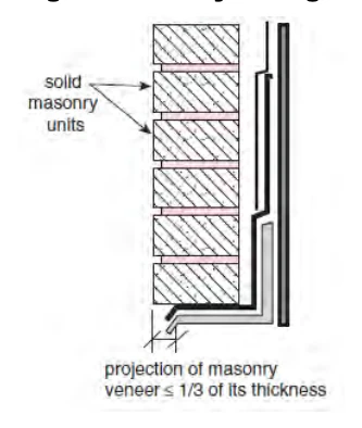
A-9.20.12.2.(2) Corbelling of Masonry Foundation Walls. Copy linkAdd bookmark
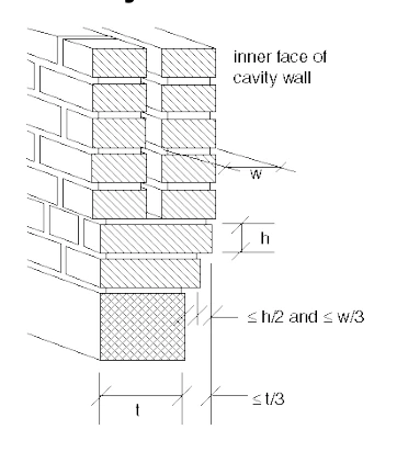
A-9.20.13.9.(3) Dampproofing of Masonry Walls. Copy linkAdd bookmark
The reason for installing sheathing paper behind masonry walls is to prevent rainwater from reaching the interior finish if it should leak past the masonry. The sheathing paper intercepts the rainwater and leads it to the bottom of the wall where the flashing directs it to the exterior via weep holes. If the insulation is a type that effectively resists the penetration of water and is installed so that water will not collect behind it, then there is no need for sheathing paper. If water that runs down between the masonry and the insulation is able to leak out at the joints in the insulation, such insulation will not act as a substitute for sheathing paper. If water cannot leak through the joints in the insulation but collects in cavities between the masonry and insulation, subsequent freezing could damage the wall. Where sheathing paper is not used, therefore, the adhesive or mortar should be applied to form a continuous bond between the masonry and the insulation. If this is not practicable because of an irregular masonry surface, then sheathing paper is necessary.
A-9.21.1.3.(1) Factory-Built Chimneys. Copy linkAdd bookmark
Certain solid-fuel burning appliances may be connected to factory-built chimneys other than those specified in Sentence 9.21.1.3.(1) if tests show that the use of such a chimney will provide an equivalent level of safety, as an alternative solution pursuant to Section 2.1. of Division C.
A-9.21.3.6.(2) Metal Chimney Liners. Copy linkAdd bookmark
Masonry chimneys with metal liners may be permitted to serve solid-fuel burning appliances if tests show that such liners will provide an equivalent level of safety, as an alternative solution pursuant to Section 2.1. of Division C.
A-9.21.4.4.(1) Location of Chimney Top. Copy linkAdd bookmark
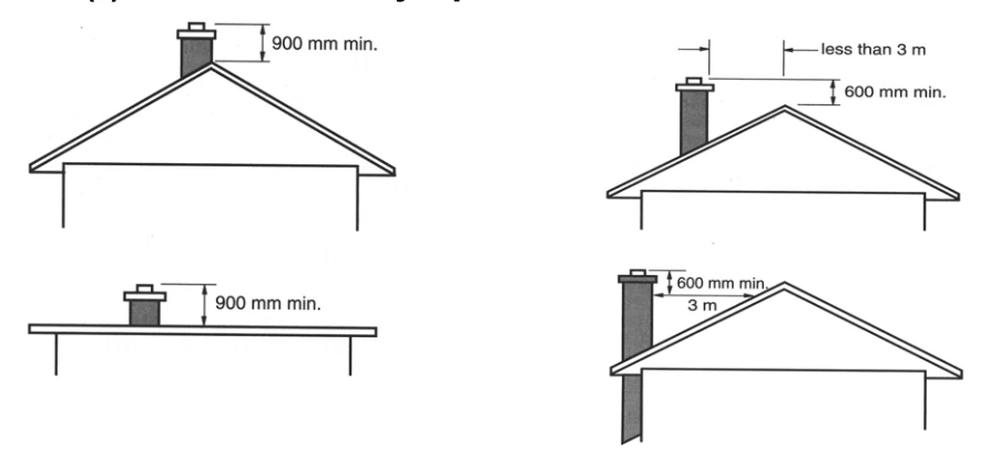
A-9.21.4.5.(2) Lateral Support for Chimneys. Copy linkAdd bookmark
Where a chimney is fastened to the house framing with metal anchors, in accordance with CAN/CSA-A370, “Connectors for Masonry”, it is considered to have adequate lateral support. The portion of the chimney stack above the roof is considered as free standing and may require additional lateral support.
A-9.21.5.1.(1) Clearance from Combustible Materials. Copy linkAdd bookmark
For purposes of this Sentence, an exterior chimney can be considered to be one which has at least one surface exposed to the outside atmosphere or unheated space over the majority of its height. All other chimneys should be considered to be interior.
A-9.23.1.1. Structural Framing Systems Other than Light Wood-Frame Construction. Copy linkAdd bookmark
The prescriptive requirements in Section 9.23. apply only to standard light wood-frame construction. Other structural framing systems, such as post, beam and plank construction, plank frame wall construction, and log construction must be designed in accordance with Part 4.
A-9.23.1.1.(1) Application of Section 9.23. Copy linkAdd bookmark
In previous editions of the Code, Sentence 9.23.1.1.(1) referred to “conventional” wood-frame construction. Over time, conventions have changed and the application of Part 9 has expanded.
The prescriptive requirements provided in Section 9.23. still focus on lumber beams, joists, studs and rafters as the main structural elements of “wood-frame construction”. The requirements recognize - and have recognized for some time - that walls and floors may be supported by components made of material other than lumber; for example, by foundations described in Section 9.15. or by steel beams described in Article 9.23.4.3. These components still fall within the general category of wood-frame construction.
With more recent innovations, alternative structural components are being incorporated into wood-frame buildings. Wood I-joists, for example, are very common. Where these components are used in lieu of lumber, the requirements in Section 9.23. that specifically apply to lumber joists do not apply to these components: for example, limits on spans and acceptable locations for notches and holes. However, requirements regarding the fastening of floor sheathing to floor joists still apply, and the use of wood I-joists does not affect the requirements for wall or roof framing.
Similarly, if steel floor joists are used in lieu of lumber joists, the requirements regarding wall or roof framing are not affected.
Conversely, Sentence 9.23.1.1.(1) precludes the installation of pre-cast concrete floors on wood-frame walls since these are not “generally comprised of ... small repetitive structural members ... spaced not more than 600 mm o.c."
Thus, the reference to “engineered components” in Sentence 9.23.1.1.(1) is intended to indicate that, where an engineered product is used in lieu of lumber for one part of the building, this does not preclude the application of the remainder of Section 9.23. to the structure, provided the limits to application with respect to cladding, sheathing or bracing, spacing of framing members, supported loads and maximum spans are respected.
A-9.23.2.4.(3) Dry Interior Environment for Interior Construction. Copy linkAdd bookmark
Interior construction, which includes sill plates, that is not in contact with the ground, but is exposed to occasional sources of moisture, is considered to be a dry interior environment for the purpose of Sentence 9.23.2.4.(3).
A-9.23.3.1.(2) Alternative Nail Sizes. Copy linkAdd bookmark
Where power nails or nails with smaller diameters than that required by Table 9.23.3.4. are used to connect framing, the following equations can be used to determine the required spacing or required number of nails.
The maximum spacing can be reduced using the following equation: Sadj = Stable x (Dred / Dtable)² where
Sadj = adjusted nail spacing ≥ 20 × nail diameter,
Stable = nail spacing required by Table 9.23.3.4.,
Dred = smaller nail diameter than that required by Table 9.23.3.1., and
Dtable = nail diameter required by Table 9.23.3.1.
The number of nails can be increased using the following equation: Nadj = Ntable x (Dtable / Dred)² where
Nadj = adjusted number of nails,
Ntable = number of nails required by Table 9.23.3.4.,
Dtable = nail diameter required by Table 9.23.3.1., and
Dred = smaller nail diameter than required by Table 9.23.3.1.
Note that nails should be spaced sufficiently far apart—preferably no less than 55 mm apart—to avoid splitting of framing lumber.
A-9.23.3.1.(3) Standard for Screws. Copy linkAdd bookmark
The requirement that wood screws conform to ANSI/ASME B18.6.1., “Wood Screws (Inch Series)” is not intended to preclude the use of Robertson head screws. The requirement is intended to specify the mechanical properties of the fastener, not to restrict the means of driving the fastener.
A-9.23.3.3.(1) Prevention of Splitting. Copy linkAdd bookmark
The intent of the phrase “staggering the nails in the direction of the grain” is illustrated in Figure A-9.23.3.3.(1).

A-Table 9.23.3.5.-B Alternative Nail Sizes. Copy linkAdd bookmark
Where power nails or nails having a different diameter than the diameters listed in CSA B111, “Wire Nails, Spikes and Staples,” are used to connect the edges of the wall sheathing to the wall framing of wood-sheathed braced wall panels, the maximum spacing should be as shown in A-Table 9.23.3.5.-B.
| Element | Nail Diameter, mm(1) | Maximum Spacing of Nails Along Edges of Wall Sheathing, mm o.c. |
|---|---|---|
| Plywood, OSB or waferboard | 2.19 – 2.52 | 75 |
| 2.53 – 2.82 | 100 | |
| 2.83 – 3.09 | 125 | |
| > 3.09 | 150 |
A-9.23.4.2. Span Tables for Wood Joists, Rafters and Beams. Copy linkAdd bookmark
In these span tables the term “rafter” refers to a sloping wood framing member which supports the roof sheathing and encloses an attic space but does not support a ceiling. The term “roof joist” refers to a horizontal or sloping wood framing member that supports the roof sheathing and the ceiling finish but does not enclose an attic space. Where rafters or roof joists are intended for use in a locality having a higher specified roof snow load than shown in the tables, the maximum member spacing may be calculated as the product of the member spacing and specified snow load shown in the span tables divided by the specified snow load for the locality being considered. The following examples show how this principle can be applied:
- (a) For a 3.5 kPa specified snow load, use spans for 2.5 kPa and 600 mm o.c. spacing but space members 400 mm o.c.
- (b) For a 4.0 kPa specified snow load, use spans for 2.0 kPa and 600 mm o.c. spacing but space members 300 mm o.c.
The maximum spans in the span tables are measured from the inside face or edge of support to the inside face or edge of support.
In the case of sloping roof framing members, the spans are expressed in terms of the horizontal distance between supports rather than the length of the sloping member. The snow loads are also expressed in terms of the horizontal projection of the sloping roof. Spans for odd size lumber may be estimated by straight line interpolation in the tables.
These span tables may be used where members support a uniform live load only. Where the members are required to be designed to support a concentrated load, they must be designed in conformance with Subsection 4.3.1.
Supported joist length in Span Tables 9.23.4.2.-H, 9.23.4.2.-I and 9.23.4.2.-J means half the sum of the joist spans on both sides of the beam. For supported joist lengths between those shown in the tables, straight line interpolation may be used in determining the maximum beam span.
Span Tables 9.23.4.2.-A to 9.23.4.2.-L and 9.23.12.3.-A to 9.23.12.3.-D cover only the most common configurations. Especially in the area of floors, a wide variety of other configurations is possible: glued subfloors, concrete toppings, machine stress rated lumber, etc. The Canadian Wood Council publishes “The Span Book”, a compilation of span tables covering many of these alternative configurations. Although these tables have not been subject to the formal committee review process, the Canadian Wood Council generates many of these span tables for wood structural components; thus, Building Code users can be confident that the alternative span tables in “The Span Book” are consistent with these span tables in the Building Code and with relevant Building Code requirements.
Spans for wood joists, rafters and beams which fall outside the scope of these tables, including those for U.S. species and individual species not marketed in the commercial species combinations described in the span tables, can be calculated in conformance with CSA O86.1, “Engineering Design in Wood”.
A-9.23.4.2.(2) Numerical Method to Establish Vibration-Controlled Spans for Wood Frame Floors. Copy linkAdd bookmark
In addition to the normal strength and deflection analyses, the calculations on which the floor joist span tables are based include a method of ensuring that the spans are not so long that floor vibrations could lead to occupants perceiving the floors as too “bouncy” or “springy”. Limiting deflection under the normal uniformly distributed loads to 1/360 of the span does not provide this assurance. Normally, vibration analysis requires detailed dynamic modelling. However, the calculations for the span tables use the following simplified static analysis method of estimating vibration-acceptable spans:
- The span which will result in a 2 mm deflection of a single joist supporting a 1 kN concentrated midpoint load is calculated.
- This span is multiplied by a factor, K, to determine the “vibration-controlled” span for the entire floor system. If this span is less than the strength- or deflection-controlled span under uniformly distributed load, the vibration-controlled span becomes the maximum span.
- The K factor is determined from the following relationship:
ln(K) = A – B • ln(Si/S184) + G where
A, B = constants, the values of which are determined from Tables A-9.23.4.2.(2)-A or -B
G = constant, the value of which is determined from Table A-9.23.4.2.(2)-C
Si = span which results in a 2 mm deflection of the joist in question under a 1 kN concentrated midpoint load
S184 = span which results in a 2 mm deflection of a 38 x 184 mm joist of same species and grade as the joist in question under a 1 kN concentrated midpoint load.
For a given joist species and grade, the value of K shall not be greater than K3, the value which results in a vibration- controlled span of exactly 3 m. This means that for vibration-controlled spans 3 m or less, K always equals K3, and for vibration-controlled spans greater than 3 m, K is as calculated.
Note that, for a sawn lumber joist, the ratio Si/S184 is equivalent to its depth (mm) divided by 184.
Due to rounding differences, the method, as presented here, might produce results slightly different from those produced by the computer program used to generate the span tables.
| Subfloor Thickness, mm | With Strapping(1) | With Bridging | With Strapping and Bridging | ||||||
|---|---|---|---|---|---|---|---|---|---|
| Joist Spacing, mm | Joist Spacing, mm | Joist Spacing, mm | |||||||
| 300 | 400 | 600 | 300 | 400 | 600 | 300 | 400 | 600 | |
| Constant A | |||||||||
| 15.5 | 0.30 | 0.25 | 0.20 | 0.37 | 0.31 | 0.25 | 0.42 | 0.35 | 0.28 |
| 19.0 | 0.36 | 0.30 | 0.24 | 0.45 | 0.37 | 0.30 | 0.50 | 0.42 | 0.33 |
| Constant B | |||||||||
| 0.33 | 0.38 | 0.41 | |||||||
Notes to Table A-9.23.4.2.(2)-A:
| Subfloor Thickness, mm | Joists with Ceiling Attached to Wood Furring(1) | Joists with Concrete Topping(2) | |||||||
|---|---|---|---|---|---|---|---|---|---|
| Without Bridging | With Bridging | With or Without Bridging | |||||||
| Joist Spacing, mm | Joist Spacing, mm | Joist Spacing, mm | |||||||
| 300 | 400 | 600 | 300 | 400 | 600 | 300 | 400 | 600 | |
| Constant A | |||||||||
| 15.5 | 0.39 | 0.33 | 0.24 | 0.49 | 0.44 | 0.38 | 0.58 | 0.51 | 0.41 |
| 19.0 | 0.42 | 0.36 | 0.27 | 0.51 | 0.46 | 0.40 | 0.62 | 0.56 | 0.47 |
| Constant B | |||||||||
| 0.34 | 0.37 | 0.35 | |||||||
Notes to Table A-9.23.4.2.(2)-B:
| Floor Description | Constant G |
|---|---|
| Floors with nailed(1) subfloor | 0.00 |
| Floor with nailed and field-glued(2) subfloor, vibration-controlled span greater than 3 m | 0.10 |
| Floor with nailed and field-glued(2) subfloor, vibration-controlled span 3 m or less | 0.15 |
Notes to Table A-9.23.4.2.(2)-C:
Additional background information on this method can be found in the following publications:
- Onysko, D.M. Serviceability Criteria for Residential Floors Based on a Field Study of Consumer Response. Project 03-50-10-008. Forintek Canada Corp., Ottawa, Canada 1985.
- Onysko, D.M. Performance Criteria for Residential Floors Based on Consumer Responses. 1988 International Conference on Timber Engineering, Seattle, September 19-22, Forest Products Research Society, Vol.1, 1988, pp. 736-745.
- Onysko, D.M. Performance and Acceptability of Wood Floors - Forintek Studies. Proceedings of Symposium/Workshop on Serviceability of Buildings, Ottawa, May 16-18, National Research Council of Canada, Ottawa, 1988.
A-Table 9.23.4.3. Spans for Steel Beams. Copy linkAdd bookmark
The spans provided in Table 9.23.4.3. reflect a balance of engineering and acceptable proven performance. The spans have been calculated based on the following assumptions:
- Simply supported beam spans
- Laterally supported top flange
- Yield strength 350 MPa
- Deflection limit L/360
- Live load = 1.9 kPa
- Dead load 1.5 kPa.
The calculation used to establish the specified maximum beam spans also applies a revised live load reduction factor to account for the lower probability of a full live load being applied over the supported area in Part 9 buildings.
A-9.23.4.3.(1) Maximum Spans for Steel Beams Supporting Floors in Dwellings. Copy linkAdd bookmark
A beam may be considered to be laterally supported if wood joists bear on its top flange at intervals of 600 mm or less over its entire length, if all the load being applied to this beam is transmitted through the joists and if 19 mm by 38 mm wood strips in contact with the top flange are nailed on both sides of the beam to the bottom of the joists supported. Other additional methods of positive lateral support are acceptable.
For supported joist lengths intermediate between those in the table, straight line interpolation may be used in determining the maximum beam span.
Design Assumptions for Tables 9.23.4.3.-A to 9.23.4.3.-J (Steel Beams Supporting Roofs and Floors)
- Density of Brick Veneer:
- Brick = 18.9 kN/m3
- Dead Load of Brick Veneer:
- 89 mm Brick = 0.089 x 18.9 = 1.68 kPa
- Brick loading on beam = 3 m high brick x 1.68 = 5.04 kN/m. This is based on a single storey wall with windows and a brick gable above the top of the stud wall. In this case, the windows in the exterior wall nullify the arch action of the brick and the load is applied uniformly along the length of the beam.
- Dead Load of Structure:
- Roof = 0.62 kPa (Asphalt shingle roof)
- Floor = 1.5 kPa as per Appendix Note A-Table 9.23.4.3.
- Live Loads:
- Floor = 1.9 kPa
- Roof = as indicated in the Tables
- Design Standards:
- CSA S304.1-94, “Masonry Design for Buildings (Limit States Design)"
- CSA S16.1-94, 'Limit States Design of Steel Structures"
- Design Assumptions:
- Simply supported beam spans
- Laterally supported top flange
- Yield strength 300 MPa
- Mid-span deflection limited to span/600 as per Clause 6.3.5.1 of CSA S304.1, for brick weight plus live load. The self-weight of structure is typically on the beam prior to the application of the brick so the deflection check need only include live and brick loads.
- For siding walls the mid-span deflection is limited to span/360 on live load.
A-9.23.4.4. Concrete Topping. Copy linkAdd bookmark
Vibration-controlled spans given in Table 9.23.4.2.-B for concrete topping are based on a partial composite action between the concrete, subflooring and joists. Normal weight concrete having a compressive strength of not less than 20 MPa, placed directly on the subflooring, provides extra stiffness and results in increased capacity. The use of a bond breaker between the topping and the subflooring, or the use of lightweight concrete topping limits the composite effects.
Where either a bond breaker or lightweight topping is used, Table 9.23.4.2.-A may be used but the additional dead load imposed by the concrete must be considered. The addition of 51 mm of concrete topping can impose an added load of 0.8 to 1.2 kPa, depending on the density of the concrete.
Example:
Assumptions:
- - basic dead load = 0.5 kPa
- - topping dead load = 0.8 kPa
- - total dead load = 1.3 kPa
- - live load = 1.9 kPa
- - vibration limit: per Note A-9.23.4.2.(2)
- - deflection limit = 1/360
- - ceiling attached directly to joists, no bridging
The spacing of joists in the span tables can be conservatively adjusted to allow for the increased load by using the spans in Table 9.23.4.2.-A for 600 mm spacing, but spacing the joists 400 mm apart. Similarly, floor beam span tables can be adjusted by using 4.8 m supported length spans for cases where the supported length equals 3.6 m.
A-9.23.8.3. Joint Location in Built-Up Beams. Copy linkAdd bookmark
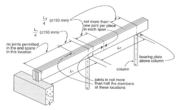
A-9.23.10.1.(2) Tall Stud Walls. Copy linkAdd bookmark
Design Assumptions for Tables 9.23.10.1.-A to 9.23.10.1.-D:
- Roof dead load is 0.5 kPa (asphalt shingle roof) as per rafter and lintel tables in the Building Code.
- Specified roof snow load is the factored load incorporating rain load as per the rafter, header and lintel spans in the Building Code.
- Wind loads are based on wind loads in the 2006 Building Code and the 2005 edition of the NBC as adopted in the Engineering Guide for Wood Frame Construction published by the Canadian Wood Council
- a. Basic wind pressure is the 1 in 50 year pressure found in Table 1.2 of MMAH Supplementary Standard SB-1
- b. Ce = 0.7 as per Sentence 4.1.7.1.(5)(b) in the Building Code
- c. CpCg = –2.1 for ultimate limit state for wind acting alone
- d. CpCg = –1.75 for the serviceability limit state
- e. CpCg = 1.5 for wind acting in combination with gravity loads
- f. Cpi varied from –0.45 to 0.3 as per User’s Guide - NBC 2005, Structural Commentaries (Part 4 of Division B). Where external wind was a pressure (wind acting in combination with axial loads) the internal wind suction coefficient of –0.45 was used. Where external wind was suction (wind acting alone) the internal wind pressure coefficient of 0.3 was used.
- g. Cgi = 2.0 as per Sentence 4.1.7.1.(6)(c) in the 2006 Building Code.
- h. The importance factors used to calculate wind loads were 1.0 at the ultimate limit state and 0.75 at the serviceability limit state as per Table 4.1.7.1. in the 2006 Building Code.
- Ultimate Limit State loads cases were in accordance with Table 4.1.3.2. in the 2006 Building Code.
- a. 1.4 axial dead load
- b. 1.25 axial dead load + 1.5 axial snow load
- c. 1.25 axial dead load + 1.5 axial snow load + 0.4 lateral wind load
- d. 1.25 axial dead load + 0.5 axial snow load + 1.4 lateral wind load
- e. 1.4 lateral wind load
- Serviceability Limits States, based on the Engineering Guide for Wood Frame Construction, were calculated using specified lateral wind loads, and included:
- a. Deflection limit of stud length/180 for walls with siding, and
- b. Deflection limit of stud length/360 for walls with brick cladding.
- Stud resistance was calculated as per CSA O86 and adopted for the Engineering Guide for Wood Frame Construction
- a. The system factors used were Case 2 load-sharing for bending moment resistance and Case 1 for compression resistance parallel to grain.
- b. A load duration factor of 1.25 was used where lateral wind acted alone or in combination with axial loads.
- Fastening requirements are based on the short-term nail resistance values given in CSA O86-01.
A-9.23.10.2. Bracing. Copy linkAdd bookmark
Traditionally, diagonal bracing has been provided at the corners of wood framed walls to provide resistance against wind racking forces. Laboratory tests have indicated, however, that the bracing that had been traditionally used contributed relatively little to the overall strength of the wall. Most of the racking resistance was in effect provided by the interior finish. Because of this, the requirements for bracing were deleted in the late 1950’s. (See “Shear Resistance of Wood Frame Walls”, by A.T. Hansen, Building Practice Note 61, Institute for Research in Construction, National Research Council, Ottawa.)
Where the interior is not finished, however, bracing is necessary if the siding itself or the sheathing does not provide the required racking strength. If panel type siding is used, or if the sheathing consists of plywood, OSB, waferboard, gypsum board, diagonal lumber, or fibreboard sheathing, additional bracing is not considered necessary because of the wind bracing provided by these materials. Where bracing is provided, it must be installed at roughly a 45° angle on each wall and in each storey, extending the full height of the storey. This type of bracing provides considerably greater resistance to wind forces than the traditional bracing, which was found to be relatively ineffective. The permission to omit bracing assumes typical house designs. Some buildings may have reduced resistance to racking forces as a result of their configuration. These include tall narrow buildings in exposed locations with large door or window openings located in the short sides. In such cases, racking resistance can be improved by ensuring that paneled sections are placed adjacent to the openings. The Code does not address the issue of bracing of the structure during construction. It is often necessary to provide temporary bracing until the interior finish or sheathing is installed; however, this is not a Code requirement.
A-9.23.10.4.(1) Fingerjoined Lumber. Copy linkAdd bookmark
The NLGA “Standard Grading Rules for Canadian Lumber”, referenced in Article 9.3.2.1. refers to two special product standards, SPS-1,"Fingerjoined Structural Lumber,” and SPS-3, “Fingerjoined Stud Lumber - Vertical Use Only”, produced by NLGA. Material identified as conforming to these standards is considered to meet the requirements in this Sentence for joining with a structural adhesive. Lumber fingerjoined in accordance with SPS-3 should be used as a vertical end-loaded member in compression only, where sustained bending or tension-loading conditions are not present, and where the moisture content of the wood will not exceed 19%. Fingerjoined lumber may not be visually regraded or remanufactured into a higher stress grade even if the quality of the lumber containing fingerjoints would otherwise warrant such regrading.
A-9.23.10.6.(3) Single Studs at Sides of Openings. Copy linkAdd bookmark
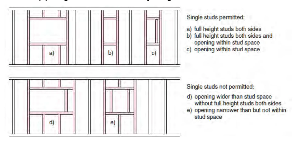
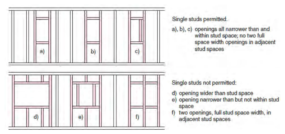
A-9.23.10.7.(2) Stud Posts Supporting Girder Trusses and Beams. Copy linkAdd bookmark
Design Assumptions:
- Roof Load = 0.62 kPa (Asphalt shingle roof)
- Design Standards: CSA 086-01, “Engineering Design in Wood”
- Design Assumptions:
- The studs are braced from buckling about their weak axis by the attachment of the wall sheathing.
- The post is designed for axial loading applied at the centre of the stud cross-section (concentric loading).
- Stud grade material has been assumed.
- The stud resistance is based on the compressive resistance parallel to grain (Pr) and the bearing resistance of the wall plate (Qr).
- In the calculation of Pr, a system factor (KH) of 1.0 was used.
- In the calculation of Qr, a size factor (Kzcp) of 1.15 was used since the wall plate width is greater than two times the thickness. A length of bearing factor (KB) of 1.0 was used since the stud post can occur at a splice in the wall plate.
- The post size has been limited to 5 plies.
- The post size is maintained through all storeys directly below the girder truss or beam until the load is transferred to the foundation wall.
A-9.23.13. Bracing for Resistance to Lateral Loads. Copy linkAdd bookmark
Subsection 9.23.13. along with Articles 9.23.3.4., 9.23.3.5., 9.23.6.1., 9.23.9.8., 9.23.15.5., 9.29.5.8., 9.29.5.9., 9.29.6.3. and 9.29.9.3. provide explicit requirements to address resistance to wind and earthquake loads in higher wind and earthquake regions of Canada.
| Applicable Requirements | Wind (HWP) | Earthquake Sa(0.2) | ||||||
|---|---|---|---|---|---|---|---|---|
| Low to Moderate | High | Extreme | Low to Moderate | High | Extreme | High | Extreme | |
| HWP < 0.80 kPa | 0.80 ≤ HWP < 1.20 kPa | HWP ≥ 1.20 kPa | Sa(0.2) ≤ 0.70 | 0.70 < Sa(0.2) ≤ 1.8 | Sa(0.2) > 1.8 | 0.70 < Sa(0.2) ≤ 1.8 | Sa(0.2) > 1.8 | |
| All Construction | All Construction | Heavy Construction(1) | Light Construction | |||||
| Design requirements in 9.23.16.2., 9.27., 9.29. | X(2) | N/A | N/A | X | N/A | N/A | N/A | N/A |
| Bracing requirements in 9.23.13. | X | X | N/A | X | X(3)(4) | N/A | X(4)(5) | N/A |
| Part 4 or CWC Guide | X | X | X | X | X | X | X | X |
Notes to Table A-9.23.13.:
A-9.23.13.1. Copy linkAdd bookmark
Bracing to Resist Lateral Loads in Low Load LocationsCopy linkAdd bookmark
All 231 locations in Ontario that are identified in Supplementary Standard SB-1, “Climatic and Seismic Data” are locations where the seismic spectral acceleration, Sa(0.2), is less than or equal to 0.70 and the 1-in-50 hourly wind pressure is less than 0.80 kPa. For buildings in these locations, Sentence 9.23.13.1.(2) requires only that exterior walls be braced using the acceptable materials and fastening specified. There are no spacing or dimension requirements for braced wall panels in these buildings.
Structural Design for Lateral Wind and Earthquake LoadsCopy linkAdd bookmark
In cases where lateral load design is required, CWC 2014, “Engineering Guide for Wood Frame Construction,” provides acceptable engineering solutions as an alternative to Part 4. The CWC Guide also contains alternative solutions and provides information on the applicability of the Part 9 prescriptive structural requirements to further assist designers and building officials to identify the appropriate design approach.
A-9.23.13.2.(1)(a)(i) Heavy Construction. Copy linkAdd bookmark
“Heavy construction” refers to buildings with tile roofs, stucco walls or floors with concrete topping, or that are clad with directly-applied heavyweight materials.
Heavyweight construction assemblies increase the lateral load on the structure during an earthquake. Assemblies should be considered as heavyweight where their average dead weight is as follows (an additional partition weight of 0.5 kPa per floor is assumed):
- floor: 0.5 to 1.5 kPa
- roof: 0.5 to 1.0 kPa
- wall (vertical area): 0.32 to 1.2 kPa
A-9.23.13.4. Braced Wall Bands. Copy linkAdd bookmark
Article 9.23.13.4. specifies the required characteristics of braced wall bands and their position in the building. Figures A-9.23.13.4.-A, A-9.23.13.4.-B and A-9.23.13.4.-C illustrate these requirements.
![Figure A-9.23.13.4.-A Braced Wall Bands in an Example Building Section [Clauses 9.23.13.4.(1)(a), (b) and (d)]](/figure-assets/bcc-2024/vol2/figure-a-9-23-13-4-a.webp)
![Figure A-9.23.13.4.-B Lapping Bands and Building Perimeter Within Braced Wall Bands [Clause 9.23.13.4.(1)(c) and Sentence 9.23.13.4.(2)]](/figure-assets/bcc-2024/vol2/figure-a-9-23-13-4-b.webp)
![Figure A-9.23.13.4.-C Braced Wall Bands at Changes in Floor Level in Split-Level Buildings [Sentence 9.23.13.4.(3)]](/figure-assets/bcc-2024/vol2/figure-a-9-23-13-4-c.webp)
A-Table 9.23.13.5. Spacing of Braced Wall Bands and Braced Wall Panels. Copy linkAdd bookmark
Identifying adjacent braced wall bands and determining the spacing of braced wall panels and braced wall bands is not complicated where the building plan is orthogonal or there are parallel braced wall bands: the adjacent braced wall band is the nearest parallel band. Figure Table A-9.23.13.5.-A illustrates spacing.
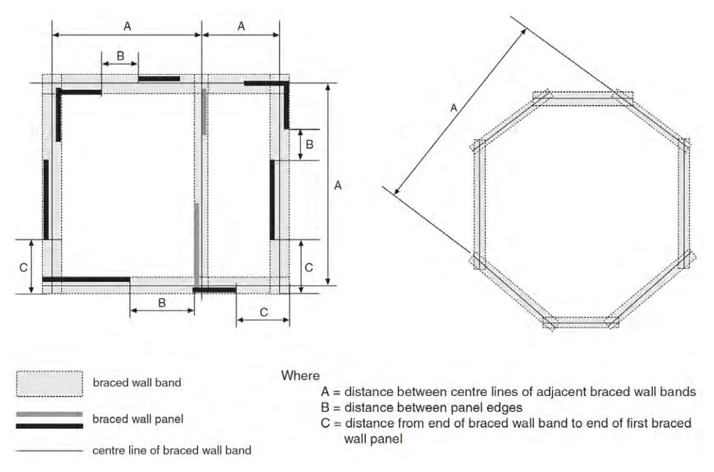
Identifying and Spacing Adjacent Non-Parallel Braced Wall BandsCopy linkAdd bookmark
Identifying the adjacent braced wall band and the spacing between braced wall bands is more complicated where the building plan is not orthogonal.
Where the plan is triangular, all braced wall bands intersect with the subject braced wall band. The prescriptive requirements in Part 9 do not apply to these cases and the building must be designed according to Part 4 with respect to lateral load resistance.
Where the braced wall bands are not parallel, the adjacent band is identified as follows using Figure Table A-9.23.13.5.-B as an example:
- Determine the mid-point of the centre line of the subject braced wall band (A);
- Project a perpendicular line from this mid-point (B);
- The first braced wall band encountered is the adjacent braced wall band (C);
- Where the projected line encounters an intersection point between two braced wall bands, either wall band may be identified as the adjacent braced wall band (complex cases).
The spacing of non-parallel braced wall bands is measured as the greatest distance between the centre lines of the bands.
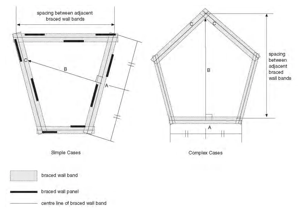
A-9.23.13.5.(2) Perimeter Foundation Walls. Copy linkAdd bookmark
Where the perimeter foundation walls in basements and crawl spaces extend from the footings to the underside of the supported floor, these walls perform the same function as braced wall bands with braced wall panels. All other braced wall bands in the basement or crawl space that align with bands with a wood-based bracing material on the upper floors need to be constructed with braced wall panels,which must be made of a wood-based bracing material, masonry or concrete. See Figure A-9.23.13.5.(2).
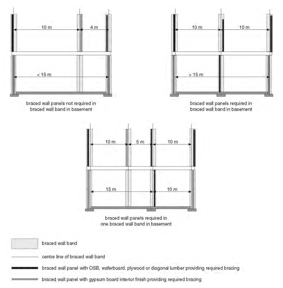
A-9.23.13.5.(3) Attachment of a Porch Roof to Exterior Wall Framing. Copy linkAdd bookmark
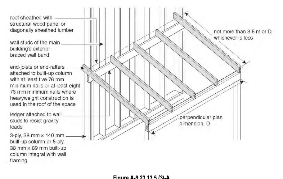
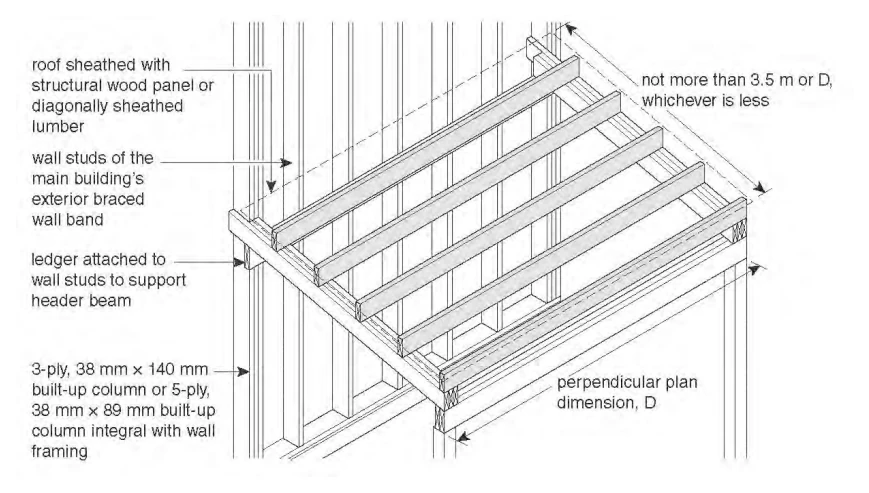
A-9.23.13.6.(5) and (6) Use of Gypsum Board Interior Finish to Provide Required Bracing. Copy linkAdd bookmark
Braced wall panels constructed with gypsum board provide less resistance to lateral loads than panels constructed with OSB, waferboard, plywood or diagonal lumber; Sentence (5) therefore limits the use of gypsum board to interior walls. Sentence (6) further limits its use to provide the required lateral resistance by requiring that walls not more than 15 m apart be constructed with panels made of wood or wood-based sheathing. See Figure A-9.23.13.6.(5) and (6).
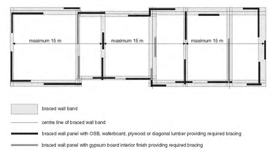
A-9.23.14.11.(2) Wood Roof Truss Connections. Copy linkAdd bookmark
Sentence 9.23.13.11.(2) requires that the connections used in wood roof trusses be designed in conformance with Subsection 4.3.1. The designer of wood trusses should be skilled in the work concerned, since wood roof trusses are complex structures which depend on a number of components (chord members, web members, cross-bracing, connectors) working together to function safely. This complexity precludes the standardization of truss design into tables comprehensive enough to satisfy the variety of roof designs required by the housing industry.
A-9.23.15.2.(4) Water Absorption Test. Copy linkAdd bookmark
A method for determining water absorption is described in ASTM D1037, “Standard Test Methods for Evaluating the Properties of Wood-Base Fiber and Particle Panel Materials”. The treatment to reduce water absorption may be considered to be acceptable if a 300 mm x 300 mm sample when treated on all sides and edges does not increase in weight by more than 6% when tested in the horizontal position.
A-9.23.15.4.(2) OSB. Copy linkAdd bookmark
CSA 0437.0, “OSB and Waferboard”, requires that Type O (aligned or oriented) panels be marked to show the grade and the direction of face alignment.
A-9.24.3.2.(3) Framing Above Doors in Steel Stud Fire Separations. Copy linkAdd bookmark
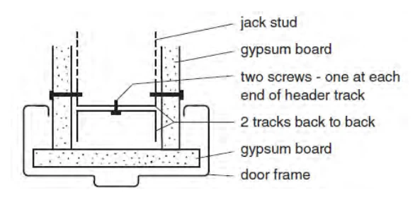
A-9.25.1.1.(2) Difference Between a Vapour Barrier and an Air Barrier. Copy linkAdd bookmark
It is important to understand the difference between the functions of a vapour barrier and an air barrier. Some materials perform both functions, while others are only intended to perform one of the two.
Vapour barrier materials are intended to restrict the movement of water vapour due to vapour pressure differentials, which are created by differences in temperature and moisture content, while air barrier materials are intended to restrict the movement of air due to air pressure differentials.
A vapour barrier does not have to be continuous or sealed to perform its function of reducing the amount of water vapour that moves across an assembly, but an air barrier must be continuous and fully sealed to prevent the movement of air across the assembly.
Further information can be found in “The difference between a vapour barrier and an air barrier,” by Quirouette, R. L., Building Performance Section, Division of Building Research, National Research Council Canada, BPN 54, July 1985.
A-9.25.2.2.(2) Flame-Spread Ratings of Insulating Materials. Copy linkAdd bookmark
Part 9 has no requirements for flame-spread ratings of insulation materials since these are seldom exposed in parts of buildings where fires are likely to start. Certain of the insulating material standards referenced in Sentence 9.25.2.2.(1) do include flame-spread rating criteria. These are included either because the industry producing the product wishes to demonstrate that their product does not constitute a fire hazard or because the product is regulated by authorities other than building authorities (e.g., Hazardous Products Act). However, the Code cannot apply such requirements to some materials and not to others. Hence, these flame-spread rating requirements are excepted in referencing these standards.
A-9.25.2.3.(3) Position of Insulation. Copy linkAdd bookmark
For thermal insulation to be effective, it must not be short-circuited by convective air flow through or around the material. If low density fibrous insulation is installed with an air space on both sides of the insulation, the temperature differential between the warm and cold sides will drive convective air flow around the insulation. If foam plastic insulation is spot adhered to a back-up wall or adhered in a grid pattern to an air permeable substrate, and is not sealed at the joints and around the perimeter, air spaces between the insulation and the substrate will interconnect with spaces behind the cladding. Any temperature or air pressure differential across the insulation will again lead to short circuiting of the insulation by air flow. Thermal insulation must therefore be installed in full and continuous contact with the air barrier or another continuous component with low air permeance. (See Appendix note A-9.25.5.1.(1) for examples of low-air-permeance materials.)
A-9.25.2.4.(3) Loose-Fill Insulation in Existing Wood-Frame Walls. Copy linkAdd bookmark
The addition of insulation into exterior walls of existing wood-frame buildings increases the likelihood of damage to framing and cladding components as a result of moisture accumulation. Many older homes were constructed with little or no regard for protection from vapour transmission or air leakage from the interior. Adding thermal insulation will substantially reduce the temperature of the siding or sheathing in winter months, possibly leading to condensation of moisture at this location.
Defects in exterior cladding, flashing and caulking could result in rain entering the wall cavity. This moisture, if retained by the added insulation, could initiate the process of decay.
Steps should be taken therefore, to minimize these effects prior to the retrofit of any insulation. Any openings in walls that could permit leakage of interior heated air into the wall cavity should be sealed. The inside surface should be coated with a low-permeability paint to reduce moisture transfer by diffusion. Finally, the exterior siding, flashing and caulking should be checked and repaired if necessary to prevent rain penetration.
A-9.25.2.4.(5) Loose-Fill Insulation in Masonry Walls. Copy linkAdd bookmark
Typical masonry cavity wall construction techniques do not lend themselves to the prevention of entry of rainwater into the wall space. For this reason, loose-fill insulation used in such space must be of the water repellent type. A test for water-repellency of loose-fill insulation suitable for installation in masonry cavity walls can be found in ASTM C516, “Standard Specification for Vermiculite Loose Fill Insulation”.
A-9.25.3.1.(1) Air Barrier Systems for Control of Condensation. Copy linkAdd bookmark
The majority of moisture problems resulting from condensation of water vapour in walls and ceiling/attic spaces are caused by the leakage of moist interior heated air into these spaces rather than by the diffusion of water vapour through the building envelope.
Protection against such air leakage must be provided by a system of air-impermeable materials joined with leak-free joints. Generally, air leakage protection can be provided by the use of air-impermeable sheet materials, such as gypsum board or polyethylene of sufficient thickness, when installed with appropriate structural support. However, the integrity of the airtight elements in the air barrier system can be compromised at the joints and here special care must be taken in design and construction to achieve an effective air barrier system.
Although Section 9.25. refers separately to vapour barriers and airtight elements in the air barrier system, these functions in a wall or ceiling assembly of conventional wood frame construction are often combined as a single membrane which acts as a barrier against moisture diffusion and the movement of interior air into insulated wall or roof cavities. Openings cut through this membrane, such as for electrical boxes, provide opportunities for air leakage into concealed spaces, and special measures must be taken to make such openings as airtight as possible. Attention must also be paid to less obvious leakage paths, such as holes for electric wiring, plumbing installations, wall-ceiling and wall-floor intersections, and gaps created by shrinkage of framing members.
In any case, air leakage must be controlled to a level where the occurrence of condensation will be sufficiently rare, or the quantities accumulated sufficiently small, and drying sufficiently rapid, to avoid material deterioration and the growth of mould and fungi.
Generally, the location in a building assembly of the airtight element of the air barrier system is not critical; it can restrict air leakage whether it is located near the outer surface of the assembly, near the inner surface or at some intermediate location. However, if a material chosen to act as an airtight element in the air barrier system also has the characteristics of a vapour barrier (i.e., low permeability to water vapour), its location must be chosen more carefully in order to avoid moisture problems. (See Appendix Notes A-9.25.4.3.(2) and A-9.25.5.1.(1)).
In some assemblies, an airtight element in the air barrier system is the interior finish, such as gypsum board, which is sealed to framing members and adjacent components by gaskets, caulking, tape or other methods to complete the air barrier system. In such cases, special care in sealing joints in a separate vapour barrier is not critical. This approach often uses no separate vapour barrier but relies on appropriate paint coatings to give the interior finish sufficient resistance to water vapour diffusion that it can provide the required vapour diffusion protection.
Section 9.25. allows for such innovative techniques, as well as the more traditional approach of using a continuous sheet, such as polyethylene, to act as an “air/vapour barrier”.
Further information is available in “Moisture Problems in Houses”, by A.T. Hansen, Canadian Building Digest 231, available from the Institute for Research in Construction, National Research Council of Canada, Ottawa K1A 0R6.
A.9.25.3.3.(9) Air Leakage and Soil Gas Control in Floors-on-Ground. Copy linkAdd bookmark
The requirement in Sentence 9.25.3.3.(9) regarding the sealing of penetrations of the air barrier also applies to hollow metal and masonry columns penetrating the floor slab. Not only the perimeters but also the centres of such columns must be sealed or blocked.
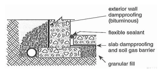
A-9.25.4.2.(2) Vapour Barrier Materials in Foundation Wall Assemblies Enclosing Basements or Heated Crawl Spaces. Copy linkAdd bookmark
In the summer, solar heating can cause condensation to form on the wall-facing side of polyethylene membranes that are installed on the warm side of foundation wall assemblies enclosing a basement or heated crawl space. Moisture in the foundation wall due to wind-driven rain is driven to the interior when the above-ground portion of the wall is exposed to solar heating. Variable-permeance vapour barrier materials allow moisture to dissipate into the basement or heated crawl space during the summer and have thus been shown to minimize the formation of condensation in foundation wall assemblies. These materials have proven effective whether installed continuously over the full area of the foundation wall or continuously over not less than the top half of the full height of the wall area, starting from the above-ground portion, with a polyethylene membrane installed over the remaining bottom portion.
Sentence 9.25.4.2.(2) is not intended to preclude the use of variable-permeance vapour barriers in above-grade wall assemblies. However, when contemplating their use in such an application, consideration should be given to the climatic conditions at the building's location.
A-9.25.4.2.(3) Normal Conditions. Copy linkAdd bookmark
The requirement for a 60 ng/(Pa·s·m2) vapour barrier stated in Sentence 9.25.4.2.(1) is based on the assumption that the building assembly is subjected to conditions that are considered normal for typical residential occupancies, and business and personal services occupancies. However, where the intended use of an occupancy includes facilities or activities that will generate a substantial amount of moisture indoors during the heating season, such as swimming pools, greenhouses, laundromats, and any continuous operation of hot tubs and saunas, the building envelope assemblies would have to demonstrate acceptable performance levels in accordance with the requirements in Part 5.
A-9.25.4.2.(6) Protection of Vapour Barriers. Copy linkAdd bookmark
The requirements of CAN/CGSB-51.33-M, “Vapour Barrier Sheet, Excluding Polyethylene, for Use in Building Construction,” were developed for paper-based vapour barriers, which are not susceptible to deterioration under prolonged exposure to direct ultraviolet (UV) radiation. Since the publication of the last edition of this standard in 1989, non-polyethylene vapour barriers have become available that are susceptible to UV-induced deterioration. These vapour barriers must be protected by a covering or installed in locations where they will not be exposed to direct UV radiation after the completion of construction. In addition, the vapour barrier manufacturer's guidance regarding the maximum allowable time of exposure to direct UV radiation should be followed where provided. Exposure to direct UV radiation most commonly occurs around window openings.
A-9.25.4.3.(2) Location of Vapour Barriers. Copy linkAdd bookmark
Assemblies in which the vapour barrier is located partway through the insulation meet the intent of this Article provided it can be shown that the temperature of the vapour barrier will not fall below the dew point of the heated interior air.
A-9.25.5.1. Location of Low Permeance Materials. Copy linkAdd bookmark
Low Air- and Vapour-Permeance Materials and Implications for Moisture AccumulationCopy linkAdd bookmark
The location in a building assembly of a material with low air permeance is not critical; the material can restrict outward movement of indoor air whether it is located near the outer surface of the assembly, near the inner surface, or at some intermediate location, and such restriction of air movement is generally beneficial, whether or not the particular material is designated as part of the air barrier system. However, if such a material also has the characteristics of a vapour barrier (i.e., low permeability to water vapour) and low thermal resistance, its location must be chosen more carefully in order to avoid moisture accumulation.
Any moisture from the indoor air which diffuses through the inner layers of the assembly or is carried by air leakage through those layers may be prevented from diffusing or being transferred through the assembly by a low air- and vapour-permeance material. This moisture transfer will usually not cause a problem if the material is located where the temperature is above the dew point of the indoor air; the water vapour will remain as vapour, the humidity level in the assembly will come to equilibrium with that of the indoor air, further accumulation of moisture will cease or stabilize at a low rate, and no harm will be done.
But if the low air- and vapour-permeance material is located where the temperature is below the dew point of the air at that location, water vapour will condense and accumulate as water or ice, which will reduce the humidity level and encourage the movement of more water vapour into the assembly. If this temperature remains below the dew point for any length of time, significant moisture could accumulate. When warmer weather returns, the presence of a material with low water vapour permeance can retard drying of the accumulated moisture. Moisture which remains into warmer weather can support the growth of decay organisms.
Due consideration should be given to the properties and location of any material in the building envelope, including paints, liquid-applied or sprayed-on and trowelled-on materials. It is recognized that assemblies that include low air- and vapour-permeance materials are acceptable, but only where these materials are not susceptible to damage from moisture or where they can accommodate moisture (for example insulated concrete walls). Further information on the construction of basement walls may be found in
- Performance Guidelines for Basement Envelope Systems and Materials,” published by NRC-IRC.
- Best Practice Guide Full-Height Basement Insulation Guide, 2008 published by MMAH
CladdingCopy linkAdd bookmark
Different cladding materials have different vapour permeances and different degrees of susceptibility to moisture deterioration. They are each installed in different ways that are more or less conducive to the release of moisture that may accumulate on the inner surface. Sheet or panel-type cladding materials, such as metal sheet, have a vapour permeance less than 60 ng/(Pa·s·m2). Sheet metal cladding that has lock seams also has a low air leakage characteristic and so must be installed outboard of a drained and vented air space. Assemblies clad with standard residential vinyl or metal strip siding do not require additional protection as the joints are not so tight as to prevent the dissipation of moisture.
SheathingCopy linkAdd bookmark
Like cladding, sheathing materials have different vapour permeances and different degrees of susceptibility to moisture deterioration.
Low-permeance sheathing may serve as the vapour barrier if it can be shown that the temperature of the interior surface of the sheathing will not fall below that at which saturation will occur. This may be the case where insulating sheathing is used.
Thermal InsulationCopy linkAdd bookmark
Where low-permeance foamed plastic is the sole thermal insulation in a building assembly, the temperature of the inner surface of this element will be close to the interior temperature. If the foamed plastic insulation has a permeance below 60 ng/(Pa·s·m2), it can fulfill the function of a vapour barrier to control condensation within the assembly due to vapour diffusion. However, where low-permeance thermal insulation is installed on the outside of an insulated frame wall, the temperature of the inner surface of the insulation may fall below the dew point. In this case, the function of vapour barrier has to be provided by a separate building element installed on the warm side of the assembly.
Normal ConditionsCopy linkAdd bookmark
The required minimum ratios given in Table 9.25.5.2. are based on the assumption that the building assembly is subjected to conditions that are considered normal for typical residential occupancies, and business and personal services occupancies.
However, where the intended use of an occupancy includes facilities or activities that will generate a substantial amount of moisture indoors during the heating season, such as swimming pools, greenhouses, the operation of a laundromat or any continuous operation of hot tubs and saunas, the building envelope assemblies would have to demonstrate acceptable performance levels in accordance with the requirements in Part 5.
A-9.25.5.1.(1) Air and Vapour Permeance Values. Copy linkAdd bookmark
The air leakage characteristics and water vapour permeance values for a number of colnmon materials are given in Table A-9.25.5.1.(1). These values are provided on a generic basis; proprietary products may have values differing somewhat from those in the Table (consult the manufacturer’s current data sheets for their products' values). The values quoted are for the material thickness listed. Water vapour permeance is inversely proportional to thickness: therefore, greater thicknesses will have lower water vapour permeance values.
| Material | Air Leakage Characteristic, L/(s•m2) at 75 Pa (Air Permeance) | Water Vapour Permeance, (Dry CuP) 60 ng/(Pa•s•m2) |
|---|---|---|
| Sheet and panel-type materials | ||
| 12.7 mm gypsum board | 0.02 | 2600 |
| • painted (1 coat primer) | negligible | 1300 |
| • painted (1 coat primer + 2 coats latex paint) | negligible | 180 |
| 12.7 mm foil-backed gypsum board | negligible | negligible |
| 12.7 mm gypsum board sheathing | 0.0091 | 1373 |
| 6.4 mm plywood | 0.0084 | 23 - 74 |
| 11 mm oriented strandboard | 0.0108 | 44 (range) |
| 12.5 mm cement board | 0.147 | 590 |
| plywood (from 9.5 mm to 18 mm) | negligible - 0.01 | 40 - 57 |
| fibreboard sheathing | 0.012 - 1.91 | 100 - 2900 |
| 17 mm wood sheathing | high - depends on no. of joints | 982 |
| Insulation | ||
| 27 mm foil-faced polyisocyanurate | negligible | 4.3 |
| 27 mm paper-faced polyisocyanurate | negligible | 61.1 |
| 25 mm extruded polystyrene | negligible | 23 - 92 |
| 25 mm expanded polystyrene (Type 2) | 0.0214 | 86 - 160 |
| fibrous insulations | very high | very high |
| 25 mm polyurethane spray foam - low density | 0.011 | 894 - 3791 |
| 25 mm polyurethane spray foam - medium density | negligible | 96(2) |
| Membrane-type materials | ||
| asphalt-impregnated paper (10 min paper) | 0.0673 | 370 |
| asphalt-impregnated paper (30 min paper) | 0.40 | 650 |
| asphalt-impregnated paper (60 min paper) | 0.44 | 1800 |
| water-resistive barriers (9 materials) | negligible - 4.3 | 30 - 1200 |
| 0.15 mm polyethylene | negligible | 1.6 - 5.8 |
| asphalt-saturated felt (#15) | 0.153 | 290 |
| building paper | 0.2706 | 170 - 1400 |
| spun-bonded polyolefin film (expanded) | 0.9593 | 3646 |
| Other materials | ||
| brick (6 materials) | negligible | 102 - 602 |
| metal | negligible | negligible |
| mortar mixes (4 materials) | negligible | 13 - 690 |
| stucco | negligible | 75 - 240 |
| 50 mm reinforced concrete (density: 2 330 kg/m3) | negligible | 23 |
Notes to Table A-9.25.5.1.(1)
- Bombaru, D., Jutras, R. and Patenaude, A. Air Permeance of Building Materials. Summary Report prepared by AIR-INS Inc. for Canada Mortgage and Housing Corporation, Ottawa, 1988. Values indicate properties of tested materials only; values for specific products may vary significantly.
- Details of Air Barrier Systems for Houses. Tarion Warranty Corporation (formerly Ontario New Home Warranty Program), Toronto, 1993.
- Kumaran, M.K., el al., ASHRAE Research Report 1018 RP, A Thermal and Moisture Transport Property Database for Common Building and Insulating Materials.
- Kumaran, M.K., Lackey, J., Normandin, N., van Reenen, D., Tariku, F., Summary Report from Task 3 of MEWS Project at the Institute for Research in Construction-Hygrothermal Properties of Several Building Materials, IRC- RR-110, March 2002.
- Mukhopadhyaya, P., Kumarai M.K., et al., Hygrothermal Properties of Exterior Claddings, Sheathing Boards, Membranes and lnsulation Materials for Building Envelope Design, Proceedings of Thermal Performance of the Exterior Envelopes of Whole Building X, Clearwater, Florida, December 2-7, 2007, pp. 1-16 (NRCC-50287).
A-9.25.5.1.(1)(a)(ii) Reduced Potential for Condensation in the Building Envelope. Copy linkAdd bookmark
The requirements in Article 9.25.5.2. aim to reduce the risk of condensation being introduced into wall assemblies due to the water vapour permeance of the outboard materials. Research has confirmed that the reduced condensation potential of exterior continuous insulation with a thermal resistance of at least 0.7 (m2·K)/W and a water vapour permeance between 30 and 1 800 ng/(Pa·s·m2) compares to reference assemblies without exterior insulation in a given geographic location and climatic exposure.
A-9.25.5.1.(3) Wood-Based Sheathing Materials. Copy linkAdd bookmark
Wood-based sheathing materials, such as plywood and OSB, that are not more than 12.5 mm thick are exempt from complying with Sentence 9.25.5.1.(1) because wood has an adaptive vapour permeance based on relative humidity: it has a low vapour permeance in an environment with low relative humidity and a higher vapour permeance in an environment with high relative humidity. (See Figure A-9.25.5.1.(3))
This adaptive vapour permeance means that wood-based materials located on the outboard side of an assembly in winter, where the RH is typically 75% or higher, are relatively vapour-open, thus allowing greater vapour movement. The same wood-based material located on the inboard side of an assembly, where the RH is typically much lower in winter, has a low vapour permeance, thus mitigating the movement of vapour.
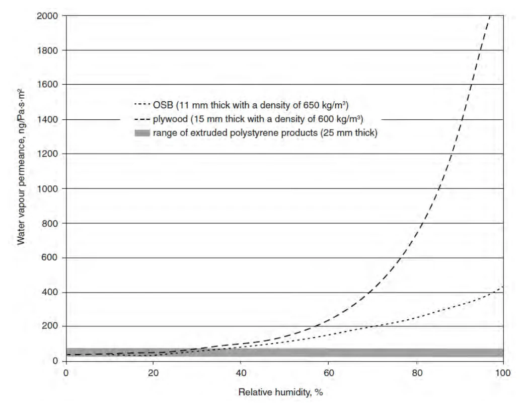
A-9.25.5.2. Assumptions Followed in Developing Table 9.25.5.2. Copy linkAdd bookmark
Article 9.25.5.2. specifies that a low air- and vapour-permeance material must be located on the warm face of the assembly, outboard of a vented air space, or within the assembly at a position where its inner surface is likely to be warm enough for most of the heating season such that no significant accumulation of moisture will occur. This last position is defined by the ratio of the thermal resistance values outboard and inboard of the innermost impermeable surface of the material in question.
The design values given in Table 9.25.5.2. are based on the assumption that the building includes a mechanical ventilation system (between 0.3 and 0.5 air changes per hour), a 60 ng/(Pa·s·m2) vapour barrier, and an air barrier (values between 0.024 and 0.1 L/(s·m2) through the assembly were used). The moisture generated by occupants and their use of bathrooms, cleaning, laundry and kitchen appliances was assumed to fall between 7.5 and 11.5 L per day.
It has been demonstrated through modelling under these conditions that assemblies constructed according to the requirements in Table 9.25.5.2. do not lead to moisture accumulation levels that may lead to deterioration as long as the average monthly vapour pressure difference between the exterior and interior sides over the heating season does not increase above 750 Pa, which would translate into an interior relative humidity (RH) of 35% in colder climates and 60% in mild climates.
Health Canada recommends indoor relative humidities between 35% and 50% for healthy conditions. ASHRAE accepts a 30% to 60% range. Environments that are much drier tend to exacerbate respiratory problems and allergies; more humid environments tend to support the spread of microbes, moulds and dust mites, which can adversely affect health.
In most of Canada in the winter, indoor RH is limited by the exterior temperature and the corresponding temperature on the inside of windows. During colder periods, indoor RH higher than 35% will cause significant condensation on windows. When this occurs, occupants are likely to increase the ventilation to remove excess moisture. Although indoor RH may exceed 35% for short periods when the outside temperature is warmer, the criteria provided in Table 9.25.5.2. will still apply. Where higher relative humidities are maintained for extended periods in these colder climates, the ratios listed in the Table may not provide adequate protection.
Table 9.25.5.2. cannot be used for occupancies that require that RH be maintained above 35% throughout the year and for those interior spaces that support activities, such as swimming, that create high relative humidities. In these cases the position of the materials must be determined according to Part 5.
lt should be noted that Part 9 building envelopes in regions with colder winters have historically performed acceptably when the indoor RH does not exceed 35% over most of the heating season. With tighter building envelopes, it is possible to raise indoor RH levels above 35%. There is no information, however, on how Part 9 building envelopes will perform when exposed to these higher indoor RH levels for extended periods during the heating season over many years. Operation of the ventilation system, as intended to remove indoor pollutants, will maintain the lower RH levels as necessary.
The method of calculating the inboard to outboard thermal resistance ratio is illustrated in Figure A-9.25.5.2. The example wall section shows three planes where low air- and vapour-permeance materials have been installed. A vapour barrier, installed to meet the requirements of Subsection 9.25.4., is on the warm side of the insulation consistent with Clause 9.25.1.2.(1)(a) and Sentences 9.25.4.1.(1) and 9.25.4.3.(2). The vinyl siding has an integral drained and vented air space consistent with Clause 9.25.1.2.(1)(c). The position of the interior face of the low-permeance insulating sheathing, however, must be reviewed in terms of its thermal resistance relative to the overall thermal resistance of the wall, and the climate where the building is located.
Comparing the RS1 ratio from the example wall section with those in Table 9.25.5.2. indicates that this wall would be acceptable in areas with Celsius degree-day values up to 7999, which includes, for example, Geraldton. (Degree-day values for various locations in Ontario are provided in MMAH Supplementary Standard SB-1.
A similar calculation would indicate that, for a similar assembly but with a 140 mm stud cavity filled with an RSI 3.52 batt, the ratio would be 0.28. Thus such a wall could be used in areas with Celsius degree-day values up to 4999, which includes, for example, Ottawa.
Similarly, if half the thickness of the same low permeance sheathing were used, the ratio with an 89 mm cavity would be 0.25, permitting its use in areas with Celsius degree-day values up to 4999. The ratio with a 140 mm cavity would be 0.16; thus this assembly could not be used anywhere, since this ratio is below the minimum permitted in Table A-9.25.5.2.
Table A-9.25.5.2. shows the minimum thicknesses of low permeance insulating sheathing necessary to satisfy Article 9.25.5.2. in various degree-day zones for a range of resistivity values of insulating sheathing. These thicknesses are based on the detail shown in Figure A-9.25.5.2. but could also be used with cladding details, such as brick veneer or wood siding, which provide equal or greater outboard thermal resistance.
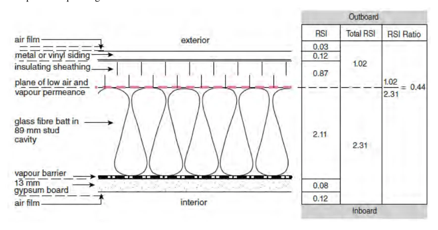
| Celsius Heating Degree-days | Min. RSI Ratio | 38 x 89 mm Framing | 38 x 140 mm Framing | ||||||||
|---|---|---|---|---|---|---|---|---|---|---|---|
| Min. Outboard Thermal Resistance, RSI | Min. Sheathing Thickness, mm | Min. Outboard Thermal Resistance, RSI | Min. Sheathing Thickness, mm | ||||||||
| Sheathing Thermal Resistance, RSI/mm | Sheathing Thermal Resistance, RSI/mm | ||||||||||
| 0.0300 | 0.0325 | 0.0350 | 0.0400 | 0.0300 | 0.0325 | 0.0350 | 0.0400 | ||||
| ≤ 4999 | 0.20 | 0.46 | 10 | 10 | 9 | 8 | 0.72 | 19 | 17 | 16 | 14 |
| 5000 to 5999 | 0.30 | 0.69 | 18 | 17 | 16 | 14 | 1.07 | 31 | 28 | 26 | 23 |
| 6000 to 6999 | 0.35 | 0.81 | 22 | 20 | 19 | 16 | 1.25 | 37 | 34 | 32 | 28 |
| 7000 to 7999 | 0.40 | 0.92 | 26 | 24 | 22 | 19 | 1.43 | 43 | 39 | 37 | 32 |
| 8000 to 8999 | 0.50 | 1.16 | 34 | 31 | 29 | 25 | 1.79 | 55 | 50 | 47 | 41 |
| 9000 to 9999 | 0.55 | 1.27 | 37 | 34 | 32 | 28 | 1.97 | 61 | 56 | 52 | 45 |
| 10000 to 10999 | 0.60 | 1.39 | 41 | 38 | 35 | 31 | 2.15 | 67 | 61 | 57 | 50 |
| 11000 to 11999 | 0.65 | 1.50 | 45 | 42 | 39 | 34 | 2.33 | 73 | 67 | 62 | 54 |
| ≥ 12000 | 0.75 | 1.73 | 53 | 49 | 45 | 40 | 2.69 | 85 | 78 | 72 | 63 |
References
- (1) Exposure Guidelines for Residential Indoor Air Quality, Environmental Health Directorate, Health Protection Branch, Health Canada, Ottawa, April 1987 (Revised July 1989).
- (2) ANSI/ASHRAE 62, “Ventilation for Acceptable Indoor Air Quality."
A-9.26.1.1.(1) Platforms that Effectively Serve as Roofs. Copy linkAdd bookmark
Decks, balconies, exterior walkways and similar exterior surfaces effectively serve as roofs where these platforms do not permit the free drainage of water through the deck. When water is driven by wind across the deck (roof) surface, it can be driven upward when it encounters an interruption.
A-9.26.2.3.(4) Fasteners for Treated Shingles. Copy linkAdd bookmark
Where shingles or shakes have been chemically treated with a preservative or a fire retardant, the fastener should be of a material known to be compatible with the chemicals used in the treatment.
A-9.26.4.1. Junctions Between Roofs and Walls or Guards. Copy linkAdd bookmark
Drainage of water from decks and other platforms that effectively serve as roofs will be blocked by walls, and blocked or restricted by guards where significant lengths and heights of material are connected to the deck. Without proper flashing at such roof-wall junctions or roof-guard junctions, water will generally leak into the adjoining elements and can penetrate into supporting assemblies below. Exceptions include platforms where waterproof curbs of sufficient height are cast-in or where the deck and wall or guard are unit-formed. In these cases, the monolithic deck-wall or deck-guard junctions will minimize the likelihood of water ingress. (See also Appendix Note A-9.26.1.1.(1).)
A-9.26.6.1.(1) Underlay Beneath Shingles. Copy linkAdd bookmark
While underlayment has not traditionally been required by the Code, some shingle manufacturers require its use beneath their products.
A-9.26.17.1.(1) Installation of Concrete Roof Tiles. Copy linkAdd bookmark
Where concrete roof tiles are to be installed, the dead load imposed by this material should be considered in determining the minimum sizes and maximum spans of the supporting roof members.
A-9.27.1.1.(5) EIFS on Walls with Cold-Formed Steel Stud Framing. Copy linkAdd bookmark
While Part 9 permits the installation of exterior insulation finish systems on walls with cold-formed steel stud framing, the design of loadbearing steel walls is outside the scope of Part 9 and is addressed in Part 4 (see Sentence 9.24.1.1.(2)).
A-9.27.2. Required Protection from Precipitation. Copy linkAdd bookmark
Part 5 and Part 9 of the Building Code recognize that mass walls and face-sealed, concealed barrier and rainscreen assemblies have their place in the Canadian context.
Mass walls are generally constructed of cast-in-place concrete or masonry. Without cladding or surface finish, they can be exposed to precipitation for a significant period before moisture will penetrate from the exterior to the interior. The critical characteristics of these walls are related to thickness, mass, and moisture transfer properties, such as shedding, absorption and moisture diffusion.
Face-sealed assemblies have only a single plane of protection. Sealant installed between cladding elements and other envelope components is part of the air barrier system and is exposed to the weather. Face-sealed assemblies are appropriate where it can be demonstrated that they will provide acceptable performance with respect to the health and safety of the occupants, the operation of building services and the provision of conditions suitable for the intended occupancy. These assemblies, however, require more intensive, regular and on-going maintenance, and should only be selected on the basis of life-cycle costing considering the risk of failure and all implications should failure occur. Climate loads such as wind-driven rain, for example, should be considered. Face-sealed assemblies are not recommended where the building owner may not be aware of the maintenance issue or where regular maintenance may be problematic.
Concealed barrier assemblies include both a first and second plane of protection. The first plane comprises the cladding, which is intended to handle the majority of the precipitation load. The second plane of protection is intended to handle any water that penetrates the cladding plane. It allows for the dissipation of this water, primarily by gravity drainage, and provides a barrier to further ingress.
Like concealed barrier assemblies, rainscreen assemblies include both a first and second plane of protection. The first plane comprises the cladding, which is designed and constructed to handle virtually all of the precipitation load. The second plane of protection is designed and constructed to handle only very small quantities of incidental water; composition of the second plane is described in Appendix Note A-9.27.3.1. In these assemblies, the air barrier system, which plays a role in controlling precipitation ingress due to air pressure difference, is protected from the elements. (See Figure A-9.27.2.)
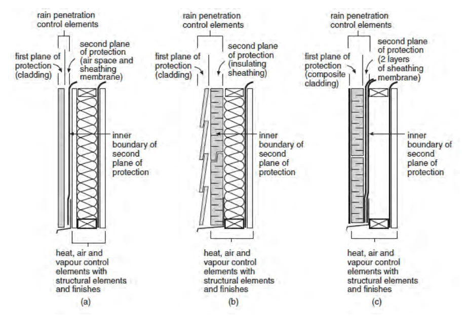
A-9.27.2.1.(1) Minimizing Precipitation Ingress. Copy linkAdd bookmark
The total prevention of precipitation ingress into wall assemblies is difficult to achieve and, depending on the wall design and construction, may not be absolutely necessary. The amount of moisture that enters a wall, and the frequency with which this occurs, must be limited. The occurrence of ingress must be sufficiently rare, accumulation sufficiently small and drying sufficiently rapid to prevent the deterioration of moisture-susceptible materials and the growth of fungi.
A-9.27.2.2.(4) Required Levels of Protection from Precipitation. Copy linkAdd bookmark
Part 9 provides guidance to assist in determining the minimum levels of protection from precipitation to be provided by cladding assemblies. Article 9.27.2.2. describes the minimum cladding assembly configuration. Designers must still consider local accepted good practice, demonstrated performance and the specific conditions to which a particular wall will be exposed when designing or selecting a cladding assembly.
A.9.27.3.1. Second Plane of Protection. Copy linkAdd bookmark
As specified in Sentence 9.27.3.1.(1), the second plane of protection consists of a drainage plane with an appropriate material serving as the inner boundary and flashing to dissipate rainwater or meltwater to the exterior.
Drainage PlaneCopy linkAdd bookmark
Except for masonry walls, the simplest configuration of a drainage plane is merely a vertical interface between materials that will allow gravity to draw the moisture down to the flashing to allow it to dissipate to the exterior. It does not necessarily need to be constructed as a clear drainage space (air space).
For masonry walls, an open rainscreen assembly is required; that is, an assembly with first and second planes of protection where the drainage plane is constructed as a drained and vented air space. Such construction also constitutes best practice for walls other than masonry walls.
Section 9.20. requires drainage spaces of 25 mm for masonry veneer walls and 50 mm for cavity walls. In other than masonry walls, the drainage space in an open rainscreen assembly should be at least 10 mm deep. Drainage holes must be designed in conjunction with the flashing.
Sheathing MembraneCopy linkAdd bookmark
The sheathing membrane described in Article 9.27.3.2. is not a waterproof material. When installed to serve as the inner boundary of the second plane of protection, and when that plane of protection includes a drainage space at least 10 mm deep, the performance of the identified sheathing membrane has been demonstrated to be adequate. This is because the material is expected to have to handle only a very small quantity of water that penetrates the first plane of protection.
If the 10 mm drainage space is reduced or interrupted, the drainage capacity and the capillary break provided by the space will be reduced. In these cases, the material selected to serve as the inner boundary may need to be upgraded to provide greater water resistance in order to protect moisture-susceptible materials in the backing wall.
Appropriate Level of ProtectionCopy linkAdd bookmark
It is recognized that many cladding assemblies with no space or with discontinuous space behind the cladding, and with the sheathing membrane material identified in Article 9.27.3.2., have provided acceptable performance with a range of precipitation loads imposed on them. Vinyl and metal strip siding, and shake and shingle cladding, for example, are installed with discontinuous drained spaces, and have demonstrated acceptable performance in most conditions. Lapped wood and composite strip sidings, depending on their profiles, may or may not provide discontinuous spaces, and generally provide little drainage. Cladding assemblies with limited drainage capability that use a sheathing membrane meeting the minimum requirements are not recommended where they may be exposed to high precipitation loads or where the level of protection provided by the cladding is unknown or questionable. Local practice with demonstrated performance should be considered. (See also Appendix Note A-9.27.2.2.(4))
A-9.27.3.4.(2) Detailing of Joints in Exterior Insulating Sheathing. Copy linkAdd bookmark
The shape of a joint is critical to its ability to shed water. Tongue and groove, and lapped joints can shed water if oriented correctly. Butt joints can drain to either side and so should not be used unless they are sealed. However, detailing of joints requires attention not just to the shape of the joint but also to the materials that form the joint. For example, even if properly shaped, the joints in insulating sheathing with an integral sheathing membrane could not be expected to shed water if the insulating material absorbs water, unless the membrane extends through the joints.
A-9.27.3.5.(1) Sheathing Membranes in Lieu of Sheathing. Copy linkAdd bookmark
Article 9.23.17.1., Required Sheathing, indicates that sheathing must be installed only where the cladding requires intermediate fastening between supports (studs) or where the cladding requires a solid backing. Cladding such as brick or panels would be exempt from this requirement and in these cases a double layer of sheathing membrane would generally be needed. The exception (Article 9.27.3.6.) applies only to those types of cladding that provide a face seal to the weather.
A-9.27.3.6. Sheathing Membrane Under Face Sealed Cladding. Copy linkAdd bookmark
The purpose of sheathing membrane on walls is to reduce air infiltration and to control the entry of wind-driven rain. Certain types of cladding consisting of very large sheets or panels with well-sealed joints will perform this function, eliminating the need for sheathing membrane. This is true of the metal cladding with lock-seamed joints sometimes used on mobile homes. However, it does not apply to metal or plastic siding applied in narrow strips which is intended to simulate the appearance of lapped wood siding. Such material does not act as a substitute for sheathing membrane since it incorporates provision for venting the wall cavity and has many loosely-fitted joints which cannot be counted on to prevent the entry of wind and rain.
Furthermore, certain types of sheathing systems can perform the function of the sheathing membrane. Where it can be demonstrated that a sheathing material is at least as impervious to air and water penetration as sheathing membrane and that its jointing system results in joints that are at least as impervious to air and water penetration as the material itself, sheathing membrane may be omitted.
A-9.27.3.8.(1) Required Flashing. Copy linkAdd bookmark
Horizontal OffsetsCopy linkAdd bookmark
Where a horizontal offset in the cladding is provided by a single cladding element, there is no joint between the offset and the cladding above. In this case, and provided the cladding material on the offset provides effective protection for the construction below, flashing is not required.
Changes in SubstrateCopy linkAdd bookmark
In certain situations, flashing should be installed at a change of substrate: for example, where stucco cladding is installed on a wood-frame assembly, extending down over a masonry or cast-in-place concrete foundation and applied directly to it. Such an application does not take into account the potential for shrinkage of the wood frame and cuts off the drainage route for moisture that may accumulate behind the stucco on the frame construction.
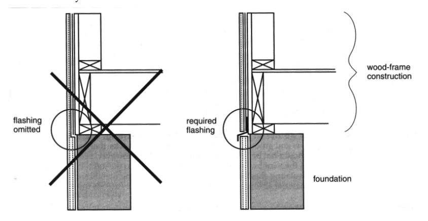
A.9.27.3.8.(3) Flashing Over Curved-Head Openings. Copy linkAdd bookmark
The requirement for flashing over openings depends on the vertical distance from the top of the trim over the opening to the bottom of the eave compared to the horizontal projection of the eave. In the case of curved-head openings, the vertical distance from the top of the trim increases as one moves away from the centre of the opening. For these openings, the top of the trim must be taken as the lowest height before the trim becomes vertical. (See Figure A-9.27.3.8.(3))
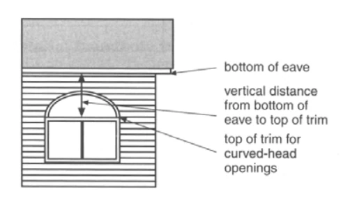
A-9.27.3.8.(4) Flashing Configuration and Positive Drainage. Copy linkAdd bookmark
Flashing ConfigurationCopy linkAdd bookmark
A 6% slope is recognized as the minimum that will provide effective flashing drainage. The 10 mm vertical lap over the building element below and the 5 mm offset are prescribed to reduce transfer by capillarity and surface tension.
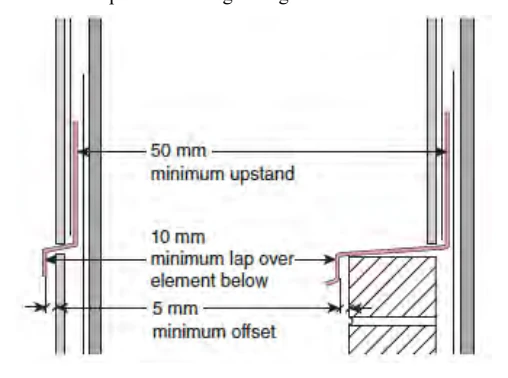
Maintaining Positive SlopeCopy linkAdd bookmark
Sentence 9.27.3.8.(4) requires that the minimum 6% flashing slope remain after expected shrinkage of the building frame. Similarly, Sentence 9.26.3.1.(4) requires that a positive slope remain on roofs and similar assemblies after expected shrinkage of the building frame.
For Part 9 wood-frame construction, expected wood shrinkage can be determined based on the average equilibrium moisture content (MC) of wood, within the building envelope assembly. According the Canadian Wood Council’s Wood Reference Handbook, the equilibrium moisture content (equilibrium MC) for wood in Ontario is 8%.
For three-storey construction to which Part 9 applies, the cumulative longitudinal shrinkage is negligible. Shrinkage need only be calculated for horizontal framing members using the following formula (from Introduction to Wood Building Technology, Canadian Wood Council, Ottawa, 1997):
Shrinkage = (total horizontal member height) x (initial MC - equilibrium MC) x (0.002)
A-9.27.3.8.(5) Protection Against Precipitation Ingress at the Sill-to-Cladding Joint. Copy linkAdd bookmark
Many windows are configured in such a way that a line of sealant is the only protection against water ingress at the sill-to-cladding joint & a location that is exposed to all of the water that flows down the window. In the past, many windows were constructed with self-flashing sills & sills that extend beyond the face of the cladding and have a drip on the underside to divert water away from the sill-to-cladding joint. This sill configuration was considered to be accepted good practice and is recognized today as providing a degree of redundancy in precipitation protection.
Self-flashing sills are sills that
- slope toward the exterior where the sills have an upward facing surface that extends beyond the jambs,
- where installed over a masonry sill, extend not less than 25 mm beyond the inner face of that sill,
- incorporate a drip positioned not less than 5 mm outward from the outer face of the cladding below or not less than 15 mm beyond the inner edge of a masonry sill, and
- terminate at the jambs or, where the face of the jambs is not at least flush with the face of the cladding and the sills extend beyond the jambs, incorporate end dams sufficiently high to protect against overflow in wind-driven rain conditions.
A wind pressure of 10 Pa can raise water 1 mm. Thus, for example, if a window is exposed to a driving rain wind pressure of 200 Pa, end dams should be at least 20 mm high.
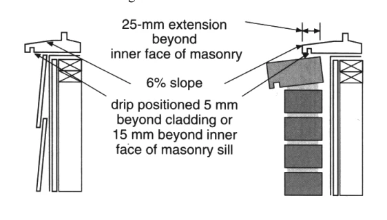
A-9.27.4.2.(1) Selection and Installation of Sealants. Copy linkAdd bookmark
Analysis of many sealant joint failures indicates that the majority of failures can be attributed to improper joint preparation and deficient installation of the sealant and various joint components. The following ASTM guidelines describe several aspects that should be considered when applying sealants in unprotected environments to achieve a durable application:
- ASTM C1193, “Standard Specification for Use of Joint Sealants",
- ASTM C1299, “Standard Guide for Use in Selection of Liquid-Applied Sealants", and
- ASTM C1472, “Standard Guide for Calculating Movement and Other Effects When Establishing Sealant Joint Width”.
The sealant manufacturer’s literature should always be consulted for recommended procedures and materials.
A-9.27.5.4.(2) Attachment of Cladding to Flat Wall ICF Units where the 1-in-50 HWP Exceeds 0.60 kPa. Copy linkAdd bookmark
For locations where the 1-in-50 hourly wind pressure is greater than 0.60 kPa, the results of testing fasteners to ASTM D1761, “Standard Test Methods for Mechanical Fasteners in Wood and Wood-Based Materials,” must be obtained from a testing facility or from the insulating concrete form manufacturer to confirm their ultimate strengths for both direct withdrawal and lateral shear. In accordance with limit states design as described in Subsection 4.1.3., the factored resistances of the fastener must be equal to or greater than the factored loads on the fastener at the spacing proposed by the designer. In order to align with the limit states design procedures used to develop Table 9.27.5.4.-B, the factored resistances must be calculated by applying a reduction factor of Φ = 0.35 to the fastener's ultimate strengths, and the factored loads must lie within the area under the line of linear interaction in a diagram that plots the factored lateral shear resistance of the fastener against its factored direct withdrawal resistance.
A-9.27.5.7. Penetration of Fasteners. Copy linkAdd bookmark
Where cladding is applied to sheathing that is not suitable for fastening, the fastener length must be increased to maintain the minimum fastener penetration depth into the nail-holding base substrate, as specified in Article 9.27.5.7.
A-9.27.9.2.(3) Grooves in Hardboard Cladding. Copy linkAdd bookmark
Grooves deeper than that specified may be used in thicker cladding providing they do not reduce the thickness to less than the required thickness minus 1.5 mm. Thus, for Type 1 or 2 cladding, grooves must not reduce the thickness to less than 4.5 mm or 6 mm depending on method of support, or to less than 7.5 mm for Type 5 material.
A-9.27.10.2.(2) Thickness of Grade O-2 OSB. Copy linkAdd bookmark
In using Table 9.27.8.2. to determine the thickness of Grade O-2 OSB cladding, substitute “face orientation” for “face grain” in the column headings.
A-9.27.11.1.(1) Steel Sheet Products. Copy linkAdd bookmark
The minimum thickness of 0.33 mm stated in Sentence 9.27.11.1.(1) refers to the total thickness of the materials, i.e., the combination of the minimum thickness of the base steel (0.29 mm) and the minimum coating thickness required by CSSBI 23M, “Standard for Residential Steel Cladding”. Note that the terms “siding” and “cladding” are often used interchangeably.
A-9.27.11.1.(2) and (3) Material Standards for Aluminum Cladding. Copy linkAdd bookmark
Compliance with Sentence 9.27.11.1.(2) and CAN/CGSB-93.2-M, “Prefinished Aluminum Siding, Soffits, and Fascia for Residential Use”, is required for aluminum siding that is installed in horizontal or vertical strips. Compliance with Sentence 9.27.11.1.(3) and CAN/CGSB-93.1-M, “Sheet, Aluminum Alloy, Prefinished, Residential”, is required for aluminum cladding that is installed in large sheets.
A-9.27.14.1.(1) Geometrically Defined Drainage Cavity. Copy linkAdd bookmark
“Geometrically defined drainage cavity” (GDDC) refers to the channels, grooves or profiles cut into the insulation backing of an EIFS panel for the purpose of providing a way for water that gets behind the system to drain out. The channels, grooves or profiles of one panel need to connect to the channels, grooves or profiles of adjacent panels in order for drainage to occur consistently and uniformly across the entire EIFS. While the size of a channel, groove or profile can be verified by inspecting a single panel, the intent of Sentence 9.27.14.1.(1) is that the required drainage capacity be achieved across the entire system.
Additional information on the design and installation of EIFS can be found in
- the EIFS Practice Manual published by the EIFS Council of Canada, and
- the manufacturer's literature.
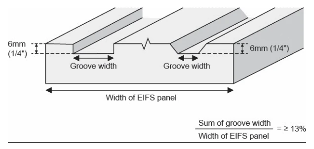
A-9.27.14.2.(2)(a) Substrates for Exterior Insulation Finish Systems. Copy linkAdd bookmark
The list of acceptable substrates for each type of EIFS can be found in a system’s respective test report to CAN/ULC-S716.1, “Standard for Exterior Insulation and Finish Systems (EIFS) – Materials and Systems”; however, the following substrates are generally considered acceptable:
- minimum 11 mm thick exposure 1 OSB classified as PS2 exterior wall sheathing
- minimum 11 mm thick exterior-rated plywood sheathing
- minimum 12.7 mm thick exterior gypsum sheathing conforming to ASTM C1177 / C1177M, “Standard Specification for Glass Mat Gypsum Substrate for Use as Sheathing”
- cementitious panels
- fibre-cement panels
- concrete block
- clay masonry
- cast-in-place concrete Note that, in some cases, the list of acceptable substrates may be limited by the EIFS manufacturer.
A-Table 9.28.4.3. Stucco Lath. Copy linkAdd bookmark
Paper-backed welded wire lath may also be used on horizontal surfaces provided its characteristics are suitable for such application.
A-9.29.5.1.(3) Application of Gypsum Board to Flat ICF Walls. Copy linkAdd bookmark
ASTM C840, “Standard Specification for Application and Finishing of Gypsum Board,” specifies requirements for the anchorage of gypsum board panels to flat wall ICF units in the section on System XVI. While the standard practice for the application of gypsum board panels over traditional vertical wood studs or metal framing members is to align the vertical joints of the panels on a supporting member, ASTM C840 requires that the vertical joints between the panels be positioned halfway between the web fastening strips of the flat wall ICF units to minimize damage to the edges of the panels during screw anchorage. The full surface of the flat wall ICF insulation panels (backed by the concrete cores) provide solid, continuous support of the taped gypsum board panel joints, which protects them from potential deflection, cracking and impact damage.
A-9.30.1.2.(1) Water Resistance. Copy linkAdd bookmark
In some areas of buildings, water and other substances may frequently be splashed or spilled onto the floor. It is preferable, in such areas, that the finish flooring be a type that will not absorb moisture or permit it to pass through; otherwise, both the flooring itself and the subfloor beneath it may deteriorate. Also, particularly in food preparation areas and bathrooms, unsanitary conditions may be created by the absorbed moisture. Where absorbent or permeable flooring materials are used in these areas, they should be installed in such a way that they can be conveniently removed periodically for cleaning or replacement, i.e., they should not be glued or nailed down. Also, if the subfloor is a type that is susceptible to moisture damage (this includes virtually all of the wood-based subfloor materials used in wood frame construction), it should be protected by an impermeable membrane placed between the finish flooring and the subfloor. The minimum degree of impermeability required by Sentence 9.30.1.2.(1) would be provided by such materials as polyethylene, aluminum foil, and most single-ply roofing membranes (EPDM, PVC).
A-9.31.6.2.(3) Securement of Service Water Heaters. Copy linkAdd bookmark
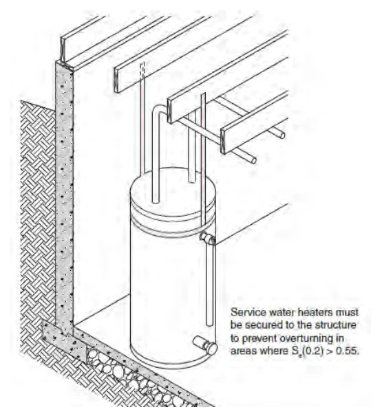
A-9.32.1.2.(2) Application of Subsection 9.32.3. and Ventilation of Houses Containing a Secondary Suite. Copy linkAdd bookmark
Ventilation for Smoke ControlCopy linkAdd bookmark
The control of smoke transfer between dwelling units in a house with a secondary suite, or between the dwelling units and other spaces in the house, is a critical safety issue. Although providing a second ventilation system to serve the two dwelling units is expensive—and potentially difficult in an existing building—it is necessary to achieving a minimum acceptable level of fire safety.
Alternative solutions to providing separate ventilation systems for the dwelling units must address smoke control. Although smoke dampers restrict the spread of smoke by automatically closing in the event of a fire, their installation in a ventilation system that serves both dwelling units in a house with a secondary suite is not considered to be a workable solution because they are very expensive, require regular inspection and maintenance, and must be reset after every activation.
Ventilation for Air ExchangeCopy linkAdd bookmark
The provision of a ventilation system for the purpose of maintaining acceptable indoor air quality is a critical health issue. However, Sentence 9.32.1.2.(3) allows exits and public corridors in houses with a secondary suite to be unventilated. Lack of active ventilation of these spaces is considered acceptable because occupants do not spend long periods of time there and because exits are somewhat naturally ventilated when doors are opened.
Considering the cost of installing separate ventilation systems, Sentence 9.32.1.2.(4) also exempts ancillary spaces in houses with a secondary suite from the requirement to be ventilated, provided that make-up air is supplied in accordance with Article 9.32.3.8.
A-9.32.1.3.(2) Venting of Laundry-Drying Equipment. Copy linkAdd bookmark
Sentence 9.32.1.3.(2) applies to the piping and ducting located within the wall assembly and not to the often flexible duct used to connect the appliance to the rigid exhaust vent duct.
A-9.32.3. Heating-Season Mechanical Ventilation. Copy linkAdd bookmark
For many years, houses were constructed without mechanical ventilation systems. They relied on natural air leakage through the building envelope for winter ventilation. However, houses have become progressively more airtight through the introduction of new products and practices, e.g., the substitution of panel sheathings, such as plywood and waferboard, for board sheathing, the replacement of paper-backed insulation batts with friction-fit batts and polyethylene film, improved caulking materials, and tighter windows and doors.
Following the energy crisis in the early 1970s, considerable emphasis was placed on reducing air leakage in order to conserve energy. Electric heating systems were encouraged and higher efficiency furnaces were developed, which further reduced air change rates in buildings. This led to concern that the natural air change in dwelling units might be insufficient in some instances to provide adequate indoor air quality. Condensation problems resulting from higher humidity levels were also a concern.
Current RequirementsCopy linkAdd bookmark
The current requirements for ventilation systems described herein include the following goals:
- provisions that are easier to understand,
- reduced probability that outdoor air distributed through a forced-air heating system will be cool enough to cause premature deterioration of the furnace heat exchanger, and
- reduced probability that the ventilation system will cause excessive depressurization of the dwelling unit.
To some extent, the first of these goals conflicts with the other two and its achievement has suffered accordingly. Only in the manner of determining the capacity of the principal ventilation fan [see Sentence 9.32.3.3.(2)] has any significant simplification been achieved.
See also Note A-9.32.3.3.(2).
A-9.32.3.1.(1) Required Ventilation. Copy linkAdd bookmark
Performance Approach [Clause 9.32.3.1.(1)(a)]Copy linkAdd bookmark
CAN/CSA-F326-M, “Residential Mechanical Ventilation Systems”, is a comprehensive performance standard. It gives experienced ventilation system designers the flexibility to design a variety of residential ventilation systems that satisfy those requirements.
Prescriptive Approach [Clause 9.32.3.1.(1)(b)]Copy linkAdd bookmark
The prescriptively described systems are intended to provide a level of performance approaching that provided by systems complying with CAN/CSA-F326-M, “Residential Mechanical Ventilation Systems”. They are included in the NBC for use by those less experienced in ventilation system design. Code users who do not find these prescriptively described systems satisfactory for their purposes, or who find them too restrictive, are free to use any other type of ventilation system that satisfies the performance requirements of CAN/CSA-F326-M.
A-9.32.3.3. Principal Ventilation System. Copy linkAdd bookmark
The principal ventilation system circulates air throughout the house for the purpose of maintaining acceptable indoor air quality. Each ventilation system has three main components:
- indoor air exhaust
- outdoor air supply
- distribution of air
Indoor Air ExhaustCopy linkAdd bookmark
The principal ventilation fan extracts indoor air. Its operation is linked with a means of introducing and distributing outdoor air to the dwelling unit at approximately the same rate at which the indoor air is exhausted, except as permitted by Article 9.32.3.6. The principal ventilation fan must be capable of drawing air from throughout the dwelling unit and exhausting it to the outdoors. Though actual usage will be determined by the occupants, the fan must be capable of continuous operation. Unfortunately, there is no standard method of testing and designating fans for continuous use. Therefore, such a designation is not a mandatory requirement. See Sentence 9.32.3.3.(4))
Supplemental exhaust fans, such as kitchen cooktop hoods and bathroom fans, provide more ventilation at point of source when needed. (See Article 9.32.3.7. and Note A-9.32.3.7.)
Outdoor Air SupplyCopy linkAdd bookmark
Outdoor air is brought into a house either through a supply duct in the exterior wall or, in exhaust-only systems, by leaks through the building envelope. (See also Note A-9.32.3.6.)
Distribution of Air(Copy linkAdd bookmark
There are two approaches to ensuring air is distributed to all parts of the house:
- in forced air heating systems, the furnace circulation fan moves the air through heating distribution ducts, (See Note A-9.32.3.4.)
- in non-forced air heating systems, a supply fan circulates air through dedicated ventilation distribution ducts. (See Note A-9.32.3.5.)
Figures A-9.32.3.3.-A to A-9.32.3.3.-F and A-9.32.3.6. show possible configurations of principal ventilation systems. However, even within these prescriptive solutions, a significant degree of flexibility is available. The configurations illustrated should therefore not be regarded as the only configurations acceptable under Sentence 9.32.3.1.(2).
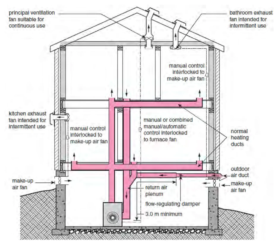
Notes to Figure A-9.32.3.3.-A:
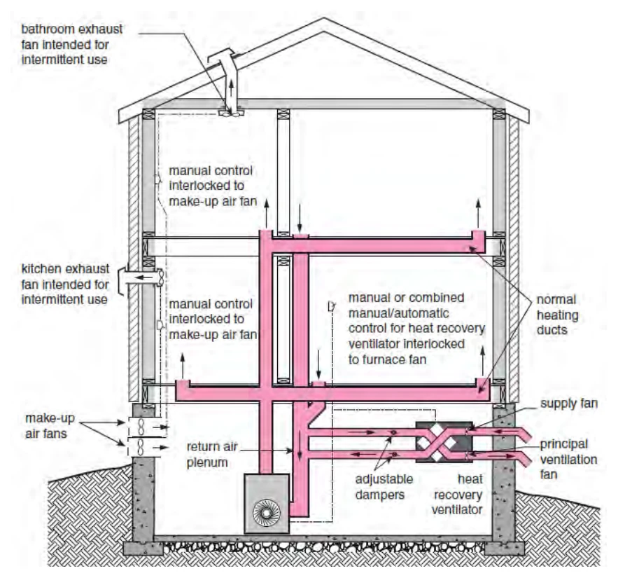
Notes to Figure A-9.32.3.3.-B:
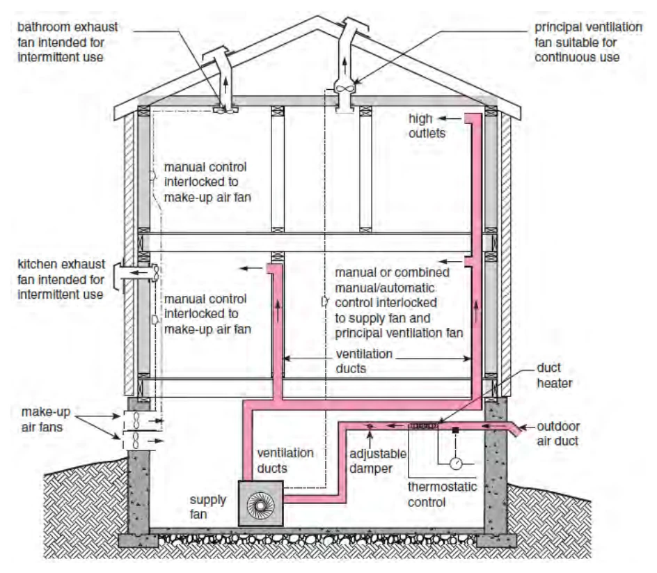
Note to Figure A-9.32.3.3.-C:
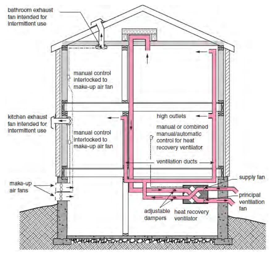
Note to Figure A-9.32.3.3.-D:
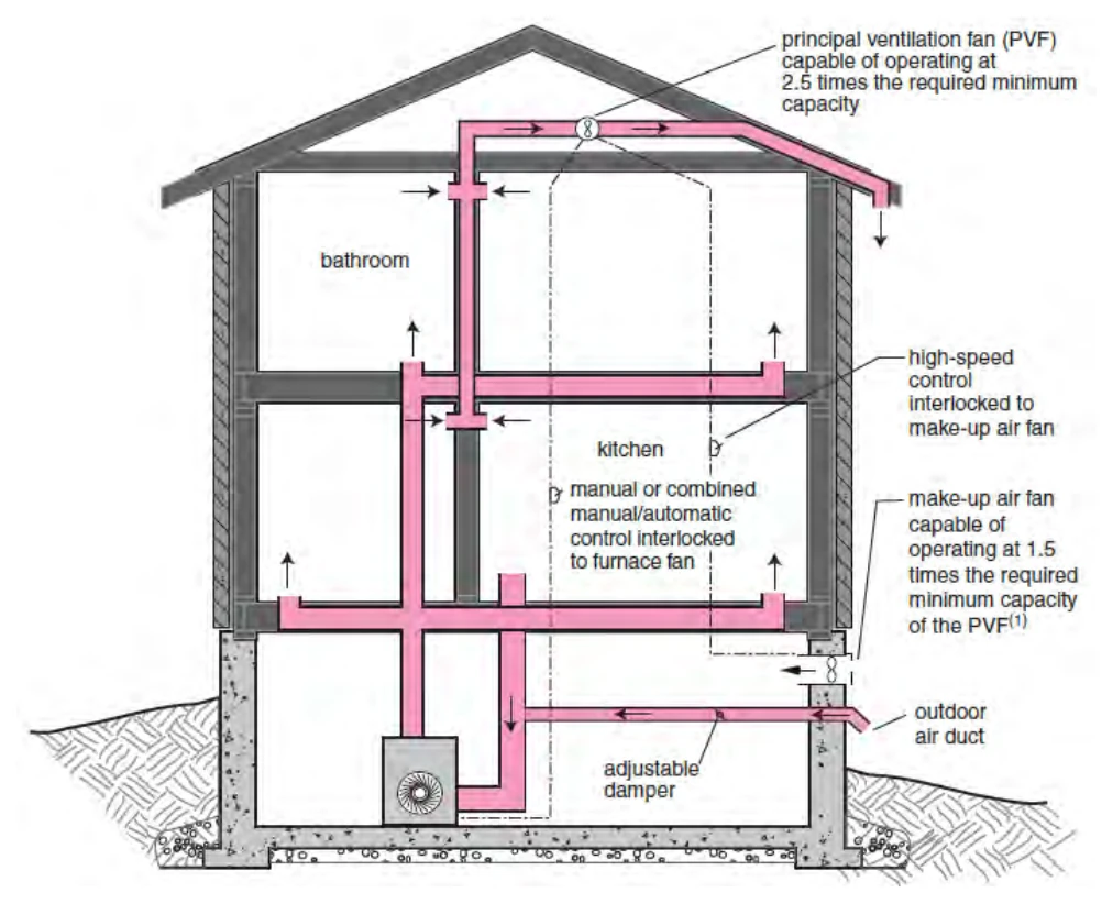
Notes to Figure A-9.32.3.3.-E:
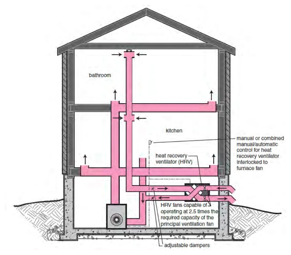
Notes to Figure A-9.32.3.3.-F:
A-9.32.3.3.(2) Normal Operating Exhaust Capacity. Copy linkAdd bookmark
The principal ventilation fan operates at a rate known as the “normal operating exhaust capacity”. This rate is intended to be suitable for use on a continuous basis at any time that an ongoing, background level of ventilation is needed, e.g. the late fall or early spring when air leakage driven by wind and inside/outside temperature differences is lowest but it is too cold to rely on open windows.
The capacity of the principal ventilation fan is determined on the basis of the number of bedrooms in the house rather than on the basis of some fraction of the house volume, as in previous editions of the Building Code. This is because the amount of ventilation required is related to the activities of people, and the number of people in the house is usually related to the number of bedrooms rather than to the size of the house. It should be emphasized that this air change rate refers to the installed capacity of the system, not to the rate of ventilation that is actually used in the house.
In many households, ventilating even at the background rate would provide more ventilation than required, resulting in unnecessarily high heating bills and perhaps excessively low indoor relative humidity. Thus, although a system with the minimum capacity must be installed, it can incorporate controls that allow the system to be used at less than its full capacity most of the time.
A maximum is set for the capacity of the principal ventilation fan because, if it were to be much larger than the ventilation needs of the household, it might never be used. The principal ventilation fan is intended to provide a relatively low level of ventilation such that it can be run continuously without too much noise and without serious energy penalty. If the installed capacity exceeds the minimum by a large margin and the fan flow cannot be reduced, there is increased probability that the fan will not be used at all, thus defeating the purpose of having it in the first place. Sentence 9.32.3.3.(2) therefore places limits on oversizing.
A-9.32.3.3.(3) Required Controls. Copy linkAdd bookmark
The principal ventilation fan must incorporate controls that allow it to be turned off. There are four main types of controls used in residential applications:
- (a) Manual on-off switch: This is the simplest form of control but, while acceptable, it is not the best means of maintaining indoor air quality. Occupants may turn the system off and forget to turn it back on, or may turn it off to save on heating bills or to reduce noise, not realizing the importance of proper ventilation.
- (b) Dehumidistat: A dehumidistat automatically activates the ventilation system in response to rising humidity. Humidity is often the main reason why ventilation is required, but not always. Depending on the activities of the occupants and the relative strengths of other sources of pollutants and humidity, the amount of ventilation required to control humidity may not be enough to control other pollutants.
- (c) Carbon Dioxide Sensor: Ventilation systems in large buildings are sometimes controlled by carbon dioxide (CO2) sensors and this technology is just beginning to be available on a residential scale. Increasing CO2 concentration is usually a good indication of decreasing air quality. But even this form of control may not be satisfactory in cases where there are unusual pollutants, such as those generated by certain hobbies.
- (d) Periodic Cycling Control: Devices are available that cause the furnace circulation fan to operate at user-set intervals if the thermostat does not call for heat. If such a device were wired so that it turns on the principal ventilation fan as well as the furnace circulation fan, it would satisfy the requirements of Article 9.32.3.4. However, if it were wired to only operate the furnace circulation fan in a system designed to Article 9.32.3.4., at times the principal ventilation fan would operate without the furnace circulation fan. Since such systems rely on the furnace circulation fan drawing in outdoor air to balance the exhaust flow through the principal ventilation fan, this would result in the exhaust flow not being balanced and the dwelling being depressurized. This configuration would therefore not be acceptable. This device would be acceptable in conjunction with a system designed in accordance with Article 9.32.3.6.
A-9.32.3.3.(5) Location of Controls. Copy linkAdd bookmark
The intent of the requirement to locate the controls in the living area is to have them easily accessible to the occupants, rather than in a little used room or unfinished basement, for example.
Installers should consider marking the manual switch with an icon depicting a fan as well as the words “Ventilation Fan.”
A-9.32.3.3.(10) Location of Exhaust Air Intakes. Copy linkAdd bookmark
Where the kitchen or a bathroom is chosen as the location for the air intake of the principal ventilation fan, the intake must be positioned high enough to capture contaminants, warm moist air, and hot gases, which tend to rise and stratify near the ceiling. These restrictions prevent the use of a cooktop exhaust or hood fan as the principal ventilation fan.
A-9.32.3.4. Ventilation Systems Used in Conjunction with Forced Air Heating Systems. Copy linkAdd bookmark
Coupling a ventilation system with a forced air heating system to provide the necessary distribution of outdoor air is relatively simple. A duct brings air from outdoors to the heating system's return air plenum. Whenever the principal ventilation fan is activated, the furnace fan is automatically activated to distribute the outdoor air. (See Sentence 9.32.3.4.(9)) Where no auxiliary supply fan is installed as per Sentence 9.32.3.4.(8), the furnace fan also drives the flow of outdoor air in through the outdoor air duct. Use of an auxiliary supply fan allows the size of the outdoor air supply duct to be reduced.
This system tempers the outdoor air before it reaches occupied areas of the house by mixing it with return air in the furnace's return air plenum. It is important that thorough mixing occur before the cold air reaches the furnace's heat exchanger, otherwise condensation could reduce the service life of the heat exchanger. The 3 m minimum distance between the furnace and the outdoor air duct connection is one means of addressing this concern. However, a well-designed mixing device is likely to be more effective, as are certain arrangements of the outdoor air duct's connection to the return air plenum. Figures A-9.32.3.4.-A and A-9.32.3.4.-B illustrate one such device and arrangements that have been shown to be effective in research carried out by Canada Mortgage and Housing Corporation (“Testing of Fresh Air Mixing Devices,” IRTA Research for Research Division of CMHC, March 1993).
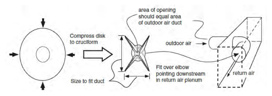
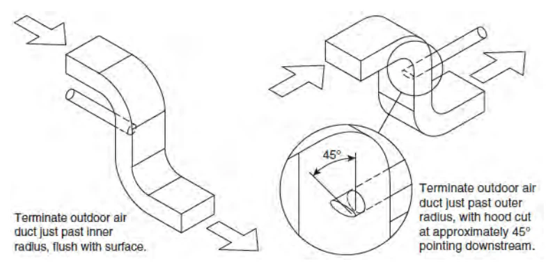
Even if the outdoor air is well mixed with the return air, in very cold weather the resulting mixed air temperature could still be lower than what the furnace heat exchanger can tolerate if there is too much outdoor air. That is why Article 9.32.3.4. includes several provisions, including Table 9.32.3.4. and the requirement to actually measure the outdoor airflow (see Sentence 9.32.3.4.(10)), to guard against this possibility. In some cases, it will not be possible to use the forced air heating system to circulate the outdoor air unless additional heating devices are used to temper the outdoor air before it reaches the furnace heat exchanger. This would be the case, for example, in a highly insulated house with a small furnace that is located in a very cold region.
The maximum outdoor airflow permitted by Table 9.32.3.4. must equal or exceed the “normal operating exhaust capacity” of the principal ventilation fan, as determined in accordance with Sentence 9.32.3.3.(2); otherwise there is an increased possibility that the mixed airflow over the furnace heat exchanger in cold weather will be colder than what the heat exchanger can tolerate. No values are listed in Table 9.32.3.4. when the maximum flow permitted exceeds the maximum capacity found in Table 9.32.3.3. since no higher outdoor airflow is required to match the flow of the principal ventilation fan.
Sentence 9.32.3.3.(9) is intended to avoid having the principal ventilation fan exhaust the outdoor air brought in through the outdoor air supply duct before it is circulated to the dwelling. The design of some advanced integrated mechanical systems is such that some portion of the outdoor air is exhausted before being circulated but this is taken into account in the design of the system and the total amount of outdoor air brought in is adjusted accordingly. This provision is not intended to preclude the use of such systems.
The duct bringing outdoor air to the furnace return air plenum must be equipped with a manual damper [see Sentence 9.32.3.4.(6)] that is adjusted (see Sentence 9.32.3.4.(10)) to balance the outdoor airflow with the flow through the principal ventilation fan. It is recommended, but not mandatory, that a motorized damper also be installed in this duct and that it be wired to be fully open when the principal ventilation fan is operating and fully closed when the principal ventilation fan is not operating. This damper will allow ventilation to occur only when the occupants have called for it by turning the “Ventilation Fan” switch to “on.” The absence of such a damper can lead to unwanted ventilation, which can result, in turn, in excessive dryness and increased heating costs in winter, and increased loading on air-conditioning equipment in the summer.
A-9.32.3.5. Ventilation Systems Not Used in Conjunction with Forced Air Heating Systems. Copy linkAdd bookmark
If there is no forced air heating system or if, for some reason, the heating system is not used to distribute the outdoor air, then a special air distribution system must be installed. Because such a system only handles ventilation air and not heating distribution air, smaller ducts can generally be used and the supply fan is quite a bit smaller than a normal furnace circulation fan. Sentences 9.32.3.5.(2) to (7) require that the supply fan operate at the same time and at the same rate as the principal ventilation fan in order to avoid either pressurizing or depressurizing the house. Pressurizing the house can lead to interstitial condensation within the building envelope. Depressurization can lead to the spillage of combustion products from heating equipment and increased entry of soil gas.
Tempering of Outdoor AirCopy linkAdd bookmark
The system described in Article 9.32.3.5. requires that the outdoor air be tempered before being circulated to the occupied areas of the house (see Sentence 9.32.3.5.(8)). Tempering can be accomplished by passing the outdoor air over some type of heating element or by mixing it with indoor air. However, the latter approach is more complex, since it requires that the ratio between the outdoor air and indoor air ducts or openings be neither too large nor too small. It was judged to be too complex to include within the context of these prescriptive requirements. Therefore, where tempering by mixing with indoor air is chosen, the system must be designed in accordance with CAN/CSA-F326-M, “Residential Mechanical Ventilation Systems.”
Distribution of Outdoor AirCopy linkAdd bookmark
Whereas a duct system associated with a forced air heating system would have ducts leading to almost all rooms, the requirements for these ventilation systems are more limited (see Sentences 9.32.3.5.(10) to (14)). The most important point is that outdoor air must be provided to each bedroom; people often spend long periods of time in the bedroom with the door closed. It is also required that at least one duct lead to every storey, including the basement.
In houses where there is no storey without a bedroom (e.g. bungalows with no basement), a duct must lead to the principal living area. Where there is more than one area that could be considered as a “living area,” at least one such area must be designated as the “principal living area.”
There is also the alternative of locating one of the exhaust air intakes for the principal ventilation fan in the principal living area, rather than supplying outdoor air directly to it; in this arrangement, the outdoor air will pass through the principal living area on its way to the exhaust fan. However, this arrangement will be less effective if only a small portion of the exhaust is withdrawn from the principal living area; thus, there is a limitation on the number of other exhaust air intakes for the principal ventilation fan. (See Sentence 9.32.3.5.(11))].
A-9.32.3.6. Exhaust-Only Ventilation Systems. Copy linkAdd bookmark
If a house does not incorporate any provision for the introduction of outdoor air, the air extracted by the principal ventilation fan will be replaced by outdoor air leaking in through the building envelope. The house will be depressurized by operation of the principal ventilation fan, and the negative internal pressure will draw outdoor air inside through any available opening. See Figure A-9.32.3.6.
This need not be of concern if the house also does not incorporate any spillage-susceptible combustion equipment. Such a system is significantly simpler in that the concern about too-cold air contacting the furnace heat exchanger is eliminated. However, in an exhaust-only system there is no control over where the outdoor air enters; e.g., the majority of envelope leaks could be into an infrequently occupied basement. Thus, it is required that houses using this system have an air distribution system so that, no matter where the outdoor air comes in, it will be mixed with the indoor air and circulated throughout the house. A forced air heating system complying with Section 9.33. satisfies the criteria for the air distribution system in Clause 9.32.3.6.(1)(b).
In a house with a very airtight building envelope, it may be difficult for the principal ventilation fan to achieve its full rated flow capacity due to high levels of house depressurization. Therefore, fans used as the principal ventilation fan in an exhaust-only ventilation system are required to have their flow rated at a higher static pressure (See Sentence 9.32.3.10.(3)) See Figure A-9.32.3.6.
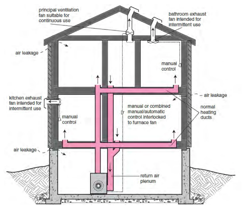
A-9.32.3.7. Supplemental Exhaust. Copy linkAdd bookmark
CAN/CSA-F326-M, “Residential Mechanical Ventilation Systems,” requires a certain amount of exhaust from kitchens to capture pollutants at the source. When the principal ventilation fan air intake is not located in the kitchen, a separate kitchen exhaust fan must be installed [see Sentence 9.32.3.7.(1)]. However, when the principal ventilation fan is located in the kitchen but is connected to multiple inlets, there will not be enough exhaust from the kitchen. Therefore, a separate kitchen exhaust fan is required in this circumstance as well, unless the exhaust rate of the principal ventilation fan can be increased when additional kitchen ventilation is needed. (See Sentence 9.32.3.7.(3))
The bathroom is another possible location for an air intake of a principal ventilation fan. As with the kitchen, if this option is not chosen, a separate bathroom exhaust fan must be installed. (See Sentence 9.32.3.7.(4))
Supplemental exhaust fans, which in most instances are located in kitchens and bathrooms, are required to be coupled to supply fans of similar capacity. The make-up air is necessary so that operation of the supplementary exhaust fan(s) will not depressurize the house. (See Sentence 9.32.3.8.(2)) See also Note A-9.32.3.8.
A-9.32.3.8. Protection against Depressurization. Copy linkAdd bookmark
When an exhaust device extracts air from a house and there are no provisions for the introduction of outdoor air, such as by means of an outdoor air duct as required by Articles 9.32.3.4. and 9.32.3.5., and no supply fans are operating simultaneously, the exhausted air will automatically be replaced by outdoor air that has infiltrated through the house's building envelope. The rate of inward leakage will automatically equal the rate of outward extraction: otherwise the house would eventually implode. The instant the exhaust device is turned on, the house pressure is lowered and the inside/outside pressure difference drives outdoor air in through any leaks it can find. See Figure A-9.32.3.8.-A.
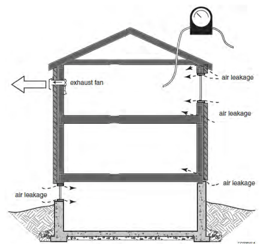
Even if the house is made more airtight, the inward leakage will equal the outward fan flow. However, because there are fewer and/or smaller leakage sites in an airtight house, it will take a larger inside/outside pressure difference to drive the same amount of air through the remaining leakage sites. See Figure A-9.32.3.8.-B.
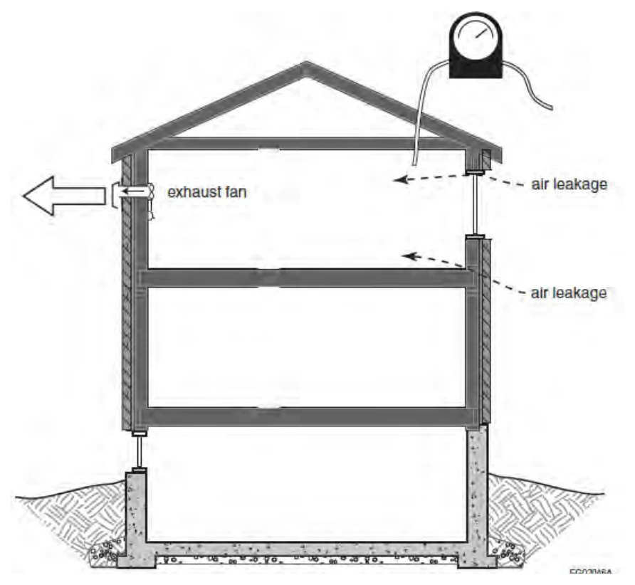
It is possible that the exhaust device will no longer be able to achieve its rated flow when operating against a very high inside/outside pressure difference. However, in this case, the inward flow will also decrease and will still be in equilibrium with the outward flow, but now at a higher inside/outside pressure difference than in a leakier house.
An exhaust device not operated in conjunction with a supply fan will always depressurize a house to some extent—even a leaky house. But it will depressurize a tight house more than it will depressurize a leaky house. And, of course, an exhaust device with a higher capacity will depressurize a house more than a device with a smaller capacity.
Spillage of Combustion ProductsCopy linkAdd bookmark
Depressurization of the house by the ventilation system or other exhaust devices can cause the spillage of combustion products from certain types of combustion appliances. The types of appliances that are susceptible to pressure-induced spillage can generally be identified by the fact that they are vented through a natural draft chimney rather than through an arrangement that uses a fan to draw the products of combustion out of the house. Naturally aspirated gas furnaces with draft hoods and oil furnaces with barometric dampers are examples of spillage-susceptible appliances.
On the other hand, some gas furnaces with induced draft venting systems and the “sealed combustion” oil furnaces commonly used in mobile homes, are more resistant to spillage. Terms used in gas appliance standards to describe categories of spillage-resistant appliances include “direct-vented” and “side-wall-vented.”
Almost all fireplaces are spillage-susceptible, even those with so called “airtight” glass doors and outside combustion air intakes, since most “airtight” doors are not really airtight. Certain types of gas combustion appliances, such as cooking appliances and “decorative appliances,” are not required to be vented. Their operation will not be significantly affected by depressurization of the house.
The Building Code addresses the potential for spillage from combustion appliances with requirements for:
- makeup air, and
- carbon monoxide alarms.
Makeup Air RequirementsCopy linkAdd bookmark
Depressurization caused by the principal ventilation system itself is not an issue in houses with balanced systems (that is, non-exhaust-only systems). However, the operation of other exhaust devices, such as stove-top barbecues, can cause depressurization. Therefore, in a house with spillage-susceptible appliances, any such exhaust devices, including the required supplemental exhaust fans, must be provided with makeup air. (See Sentence 9.32.3.8.(2))
In the past, the NBC and other codes and standards have tended to rely on the passive supply of makeup air through makeup air openings. This is no longer considered to be a reliable approach in the context of a simple, prescriptively described system without sophisticated controls on depressurization. Therefore, the makeup air must be provided by a supply fan that is automatically activated whenever the exhaust device that requires the makeup air is activated. (See Sentences 9.32.3.8.(2) and (3))
The need for makeup air can be avoided by not using spillage-susceptible combustion equipment.
Carbon Monoxide Alarm Requirements for Solid-Fuel-Burning AppliancesCopy linkAdd bookmark
Even at a relatively low level of depressurization, certain open-type solid-fuel-burning appliances, such as fireplaces, or even closed-type solid-fuel-burning appliances whose stoking doors are left open, can spill products of combustion into the house when operating in their “die down” or smouldering stages. In the absence of more sophisticated design and installation controls to prevent such levels of depressurization (such as those mentioned in CAN/CSA-F326-M, “Residential Mechanical Ventilation Systems,” the only available safeguard is to require the installation of a carbon monoxide (CO) alarm in any room incorporating a solid-fuel-burning device. (See Sentence 9.32.3.9.(3)) Where this is not acceptable, the prescriptively described alternatives must be abandoned and a system fully complying with CAN/CSA-F326-M must be designed.
One advantage of solid-fuel-burning devices is that their spillage is readily detected by a carbon monoxide alarm (which is not true of gas- or oil-burning devices). Therefore, where this is the only type of spillage-susceptible combustion device present, one has the choice of not providing makeup air for exhaust devices ([see Sentence 9.32.3.8.(6)): the carbon monoxide alarm required by Sentence 9.32.3.9.(3) will warn occupants when depressurization is causing spillage.
Battery-operated carbon monoxide alarms are permitted, but they must be mechanically fixed to a surface.
See also Note A-9.32.3.9.
A-9.32.3.9. Carbon Monoxide Alarms. Copy linkAdd bookmark
Carbon monoxide (CO) is a colourless, odourless gas that can build up to lethal concentrations in an enclosed space without the occupants being aware of it. Thus, where an enclosed space incorporates or is near a potential source of CO, it is prudent to provide some means of detecting its presence.
Dwelling units have two common potential sources of CO:
- fuel-fired space- or water-heating equipment within the dwelling unit or in adjacent spaces within the building, and
- attached storage garages.
Most fuel-fired heating appliances do not normally produce CO and, even if they do, it is normally conveyed outside the building by the appliance's venting system. Nevertheless, appliances can malfunction and venting systems can fail. Therefore, the provision of appropriately placed CO alarms in the dwelling unit is a relatively low-cost back-up safety measure.
Similarly, although Article 9.10.9.18. requires that the walls and floor/ceiling assemblies separating attached garages from dwelling units incorporate an air barrier system, there have been several instances of CO from garages being drawn into houses, which indicates that a fully gas-tight barrier is difficult to achieve. The likelihood of preventing the entry of all CO is decreased if the dwelling unit is depressurized in relation to the garage. This can readily occur due to the operation of exhaust equipment or simply due to the stack effect created by heating the dwelling unit. Again, CO alarms in the dwelling unit provide a relatively low-cost back-up safety measure.
See also Note A-9.32.3.8.
A-9.32.3.10. Fans. Copy linkAdd bookmark
The principal ventilation fan is intended to be run for long periods. Even the supplemental exhaust fans may be used for significant periods. Therefore, all fans that are mounted such that their sound is likely to intrude on the household, other than kitchen exhaust fans, are required to have reasonably low sound ratings so that building occupants will not turn them off before the need for ventilation has been met.
A-9.32.3.11. Ducts. Copy linkAdd bookmark
Table 9.32.3.11.-A is based on the data listed in Table 9, “Friction Chart for Round Ducts,” Chapter 32, of the ASHRAE 1997, “ASHRAE Handbook – Fundamentals.” The allowable duct lengths listed in the Table have been calculated assuming the “equivalent lengths” of ducts are four times their physical lengths. The static pressure offset to account for building pressures is 10 Pa. Using Table 9.32.3.11.-A will generally result in very conservatively sized (i.e. larger) ducts compared to what would be achieved using the normal duct design procedures referenced in Subsection 9.33.4.
A-9.32.3.12. Heat Recovery Ventilators. Copy linkAdd bookmark
Enthalpy recovery ventilators (ERVs) are a type of heat recovery ventilator and must therefore comply with the requirements of Article 9.32.3.12.
A-9.33.1.1.(2) Combustion Air and Tight Houses. Copy linkAdd bookmark
The operation of an air exhaust system or of a fuel-burning appliance removes the air from a house, creating a slight negative pressure inside. In certain cases the natural flow of air up a chimney can be reversed, leading to a possible danger of carbon monoxide poisoning for the inhabitants.
Newer houses are generally more tightly constructed than older ones because of improved construction practices, including tighter windows, weather stripping and caulking. This fact increases the probability that infiltration may not be able to supply enough air to compensate for simultaneous operation of exhaust fans, fireplaces, clothes dryers, furnaces and space heaters. It is necessary, therefore, to introduce outside air to the space containing the fuel-burning appliance. Information regarding combustion air requirements for various types of appliances can be found in the installation standards referenced in Articles 6.2.1.4. and 9.33.1.2. In the case of solid-fuel burning stoves, ranges and space heaters, CAN/CSA-B365, “Installation Code for Solid-Fuel-Burning Appliances and Equipment” suggests that the minimum size of openings be determined by trial and error to accommodate the flue characteristics, the firing rate, the building characteristics, etc., and that, as a guide, the combustion air opening should be 0.5 times the flue collar area.
Further information is available in Canadian Building Digest 222, “Airtight Houses and Carbon Monoxide Poisoning”, from the Institute for Research in Construction, National Research Council of Canada, Ottawa K1A 0R6.
A-9.33.4.3.(1) Heating System Controls. Copy linkAdd bookmark
Where a single heating system serves two dwelling units and common spaces a house with a secondary suite, it must be possible for the occupants to control the temperature in their own suites. Sentence 9.33.4.3.(1), which applies only to electric, fuel-fired or unitary heaters and hydronic heating systems, specifies that separate temperature controls must be provided in each dwelling unit in a house with a secondary suite; however, the controls for shared spaces may be located in those spaces or in one of the suites.
A-9.33.5.3.(1) Design, Construction and Installation Standard for Solid-Fuel- Burning Appliances. Copy linkAdd bookmark
CSA B365, “Installation Code for Solid-Fuel-Burning Appliances and Equipment” is essentially an installation standard, and covers such issues as accessibility, air for combustion and ventilation, chimney and venting, mounting and floor protection, wall and ceiling clearances, installation of ducts, pipes, thimbles and manifolds, and control and safety devices. But the standard also includes a requirement that solid-fuel-burning appliances and equipment satisfy the requirements of one of a series of standards, depending on the appliance or equipment, therefore also making it a design and construction standard. It is required that stoves, ranges, central furnaces and other space heaters be designed and built in conformity with the relevant referenced standard.
A-9.33.5.3.(2) Emission Limits. Copy linkAdd bookmark
CSA B415.1-10 and the US EPA Standard cover appliances that burn biomass fuels other than coal and require appliances equipped with catalytic combustors have an average particulate emission rate ≤ 2.5 g/h and appliances not equipped with catalytic combustors have an average particulate emission rate ≤ 4.5 g/h. Both CSA and EPA test particulate emissions using the same testing methods. These standards do not cover site-built masonry fireplaces or site-built masonry heaters. They do not apply to factory-built fireplaces with a minimum burn rate ≥ 5 kg/h.
A-9.33.6.13. Return Air Systems. Copy linkAdd bookmark
It is a common practice to introduce outdoor air to the house by means of an outdoor air duct connected to the return air plenum of a forced air furnace. This is an effective method and is a component of one method of satisfying the mechanical ventilation requirements of Subsection 9.32.3. However, some caution is required. If the proportion of cold outside to warm return air is too high, the resulting mixed air temperature could lead to excessive condensation in the furnace heat exchanger and possible premature failure of the heat exchanger. CAN/CSA-F326-M, “Residential Mechanical Ventilation Systems,” requires that this mixed air temperature not be below 15.5°C when the outdoor temperature is at the January 2.5% value. It is also important that the outdoor air and the return air mix thoroughly before reaching the heat exchanger. Note A-9.32.3. provides some guidance on this.
A-9.33.10.2.(1) Factory-Built Chimneys. Copy linkAdd bookmark
Under the provisions of Article 1.2.1.1. of Division A, certain solid-fuel-burning appliances may be connected to factory-built chimneys other than those specified in Sentence 9.33.10.2.(1) if tests show that the use of such a chimney will provide an equivalent level of safety.
A-9.40. Cold Room Slabs. Copy linkAdd bookmark
Design Assumptions:
- Density of Reinforced Concrete = 23.5 kN/m3.
- Live Loads - As per Sentence 9.4.2.3 (1) of the Building Code, the live load is the lesser of the following:
- 1.9 kPa,
- Specified roof snow load, which for Ontario is up to 2.9 kPa.
Therefore a specified design load of 3.0 kPa is appropriate; however, the slab specified is capable of carrying higher live loads since the crack control requirements of CSA A23.3 and cover requirements as given below govern the design of the slab.
- Design Standards: CSA A23.3-94, “Design of Concrete Structures”.
- Exposure and Cover for Reinforcing Steel:
- The slab is considered to be exposed to weather and de-icing chemicals.
- Minimum top cover is 60 mm as per CSA A23.3 Clause A15.1.7.1 plus a 12 mm tolerance on placement.
- Minimum bottom cover is 30 mm as per CSA A23.3 Clause A12.6.2 (slab cast against formwork).
- For 10M reinforcing bars the minimum slab thickness is 72 mm cover + 11.3 mm bar + 11.3 mm bar + 30 mm cover = 125 mm.
- Design Assumptions:
- Concrete compressive strength of 32 MPa at 28 days as per Sentence 9.3.1.6.(1) of the Building Code.
- Reinforcing steel yield strength of 400 MPa.
- Slab design is based on a one-way slab simply supported on foundation walls along the edges. Since the slab can be square or rectangular, the same steel is provided in both directions.
- Maximum span is limited to 20 times the slab thickness as per CSA A23.3 Table 9.1.
A-10 Change of Use.Copy linkAdd bookmark
The successful application of Code requirements to a change of use of an existing building or parts thereof without any proposed construction becomes a matter of balancing the cost of implementing a requirement with the relative importance of that requirement to the overall Code objectives. In general, the degree to which any particular requirement can be relaxed without affecting the intended level of safety of the Code requires considerable judgment on the part of both the designer and the authority having jurisdiction. Therefore, this Part sets out a minimum performance level which the change of use must maintain.
A-11.2.1.1.(1)(a) Construction Index. Copy linkAdd bookmark
The scale of 1 (lowest) to 8 (highest) was formulated for existing buildings, to be used to determine their existing performance level; the numbers, or indices, were established based on the requirements of 3.2.2.20. to 3.2.2.92. Classification of existing buildings will now be in accord with Table 11.2.1.1.A. rather than Subsection 3.2.2. The construction index is established by evaluating all floors and roofs of the existing building.
A-11.2.1.1.(1)(b) Hazard Index. Copy linkAdd bookmark
While the construction index refers to construction of the existing building, hazard index refers to the proposed major occupancy or use of the building; the scales of 1 (lowest hazard) to 8 (highest hazard) are compatible with those of the construction index. In effect, a building with a C.I. of say 3, will support a major occupancy with a H.I. of 3 or lower; if you wish to change to a major occupancy with a H.I. higher than 3, then you must increase the fire protection construction of the building to support that higher hazard according to Table 11.2.1.1.A., or provide the additional upgrading in accordance with Column 4 of Table 11.4.3.4.A.
A-11.3.1.1.(1) Performance Level. Copy linkAdd bookmark
States the philosophy and intent of this Article: “after construction, the performance level of the building may remain the same, or be made better, but may not be made worse”.
A-11.3.1.2.(1) New and Extension of Existing Building System. Copy linkAdd bookmark
Generally, new or extended building systems should follow the Building Code for new construction, and where necessary, may seek some relief through compliance alternatives, alternative measures or match existing.
A-11.3.3.1. Basic Renovation. Copy linkAdd bookmark
The basic renovation is the simplest form of renovation; the work area is limited in size (within a suite or room), and does not involve a decrease in performance level of the building. The limit in size assures that accesses to exits, corridor separations, or other life safety systems are left intact, where less than a full floor area is under renovation.
A-11.3.3.2. Extensive Renovation. Copy linkAdd bookmark
In cases where extensive renovation of the building is proposed, there is generally no reason why the new systems should not comply with new construction requirements; in this case the applicant may seek relief only through “alternative measures”, should a construction difficulty arise that requires such relief. This would apply to the substantial renovation of the entire building.
A-11.3.3.2.(3) Application of Limited Barrier-Free Design Requirements in Renovations. Copy linkAdd bookmark
Certain barrier-free design provisions must be incorporated into all renovations where new interior walls or floor assemblies are installed other than in a suite described in Sentence (2) or in a suite in a building described in Sentence 3.8.1.1.(1). This includes construction within suites less than 300 m2 and suites on storeys or floor levels not accessible by a barrier-free path of travel. In those cases, any new construction is subject to the barrier-free design provisions listed in 11.3.3.2.(3). Sentence 1.3.3.3C.(1) of Division A continues to apply, so that any existing construction that is not being materially altered as part of the renovation need not include barrier-free design features.
The intent of these provisions is to make more suites and buildings accessible for people with sensory and other non-mobility disabilities. Not every person with a disability uses a wheelchair. Many people who use mobility aids such as canes or service animals or who have sensory disabilities are able to navigate stairs but would benefit from certain barrier-free elements such as lever door handles or an ambulatory washroom stall.
A-11.4.3.1. Compensating Construction. Copy linkAdd bookmark
Where the performance level of the building or part of the building is reduced through Subsection 11.4.2., compensating construction will be required to restore the performance level to its former state, of the early warning and evacuation systems, the fire and structural protection construction of the building. The amount of upgrading required depends on the results of a performance level evaluation.
The extent, or areas covered, of this upgrading include the protection of the surrounding existing areas from the portion being renovated, and the means of egress from the building if adversely affected by the renovation.
A-11.4.3.2.(1) Structural. Copy linkAdd bookmark
Provides, subject to any of three conditions, for adequacy of support for floors that will be receiving increased dead or live loads: options are restriction of loads or upgrading of support systems.
A-11.4.3.3. Increase in Occupant Load. Copy linkAdd bookmark
Where the increase is greater than 15%, and construction takes place, the performance level is reduced and must be restored as required in Table 11.4.3.3.
Where the increase is 15% or less, and construction takes place, the performance level is reduced. Where the new occupant load is more than 15% above the exit capacity or for which a fire alarm system is required. The performance level must be restored as required by Table 11.4.3.3.
Smaller buildings, of 14 persons or less in boarding houses, and 16 persons or less in dwelling units, are exempt.
A-11.4.3.4. Change in Major Occupancy. Copy linkAdd bookmark
Provided construction takes place, a change in major occupancy to one of a greater hazard index reduces the performance level. An increase of the hazard index will trigger the classification of the entire building as to its construction index and hazard index under Table 11.4.3.3., Table 11.4.3.4.A. and B, to determine what upgrading, if any is required to ensure that the building will support that new hazard.
A-11.5.1. Compliance Alternatives. Copy linkAdd bookmark
Subsection 11.5.1. allows compliance alternatives to be used, in lieu of certain requirements in other Parts of Division B. Alternatives to requirements in Part 3, 4, 6 or 8 may be used subject to the chief official’s satisfaction, while alternatives to Parts 9 and 12 requirements are not subject to this condition.
A-12.3.1.5.(1) Residential Furnaces. Copy linkAdd bookmark
Where an existing furnace without a brushless direct current motor is replaced in a dwelling unit or house, replacement with a furnace with similar characteristics would provide an acceptable performance level, since the furnace flow rate and ductwork size would be compatible and this alteration to the heating and cooling system would not reduce the performance level.