Division B
Part 4 - Structural Design
Section 4.1. Structural Loads and Procedures Copy linkAdd bookmark
4.1.1. General Copy linkAdd bookmark
4.1.1.1. Scope Copy linkAdd bookmark
(1)The scope of this Part shall be as described in Subsection 1.3.3. of Division A.
4.1.1.2. Definitions Copy linkAdd bookmark
(1)Words that appear in italics in this Part are defined in Article 1.4.1.2. of Division A.
4.1.1.3. Design Requirements Copy linkAdd bookmark
(1)Buildings and their structural members and connections, including formwork and falsework, shall be designed to have sufficient structural capacity and structural integrity to safely and effectively resist all loads, effects of loads and influences that may reasonably be expected, having regard to the expected service life of buildings, and shall in any case satisfy the requirements of this Section. (See Note A-4.1.1.3.(1))
(2)Buildings and their structural members shall be designed for serviceability, in accordance with Articles 4.1.3.4., 4.1.3.5. and 4.1.3.6. (See Note A-4.1.1.3.(2))
(3)All permanent and temporary structural members, including the formwork and falsework of a building, shall be protected against loads exceeding the specified loads during the construction period except when, as verified by analysis or test, temporary overloading of a structural member would result in no impairment of that member or any other member.
(4)Reserved.
(5)Precautions shall be taken during all phases of construction to ensure that the building is not damaged or distorted due to loads applied during construction.
4.1.1.4. Reserved Copy linkAdd bookmark
4.1.1.5. Design Basis Copy linkAdd bookmark
(1)Except as provided in Sentence (2), buildings and their structural members shall be designed in conformance with the procedures and practices provided in this Part.
(2)Provided the design is carried out by a person especially qualified in the specific methods applied and provided the design demonstrates a level of safety and performance in accordance with the requirements of this Part, buildings and their structural components falling within the scope of this Part that are not amenable to analysis using a generally established theory may be designed by,
(a)evaluation of a full-scale structure or a prototype by a loading test, or
(b)studies of model analogues.
(See Note A-4.1.1.5.(2))
4.1.2. Specified Loads and Effects Copy linkAdd bookmark
4.1.2.1. Loads and Effects (See Note A-4.1.2.1.) Copy linkAdd bookmark
(1)Except as provided in Article 4.1.2.2., the following categories of loads, specified loads and effects shall be taken into consideration in the design of a building and its structural members and connections: D ………….. dead load – a permanent load due to the weight of building components, as specified in Subsection 4.1.4., E …………… earthquake load and effects – a rare load due to an earthquake, as specified in Subsection 4.1.8., H ……..…… a permanent load due to lateral earth pressure, including groundwater, L …………… live load – a variable load due to intended use and occupancy (including loads due to cranes and the pressure of liquids in containers), as specified in Subsection 4.1.5., LXC ………… live load exclusive of crane loads, C …………… live load due to cranes including self weight, Cd …………. self weight of all cranes positioned for maximum effects, C7 …………. crane bumper impact load, P …………… permanent effects caused by pre-stress, S …………… variable load due to snow, including ice and associated rain, as specified in Article 4.1.6.2., or due to rain, as specified in Article 4.1.6.4., T …………… effects due to contraction, expansion, or deflection caused by temperature changes, shrinkage, moisture changes, creep, ground settlement, or a combination thereof, and (See Note A-4.1.2.1.(1)) W ………….. wind load – a variable load due to wind, as specified in Subsection 4.1.7., where
(a)load means the imposed deformations (i.e. deflections, displacements or motions that induce deformations and forces in the structure), forces and pressures applied to the building structure,
(b)permanent load is a load that changes very little once it has been applied to the structure, except during repair,
(c)variable load is a load that frequently changes in magnitude, direction or location, and
(d)rare load is a load that occurs infrequently and for a short time only.
(2)Minimum specified values of the loads described in Sentence (1), as set forth in Subsections 4.1.4. to 4.1.8., shall be increased to account for dynamic effects where applicable.
(3)For the purpose of determining specified loads S, W or E in Subsections 4.1.6., 4.1.7. and 4.1.8., buildings shall be assigned an Importance Category based on intended use and occupancy, in accordance with Table 4.1.2.1. (See Note A-4.1.2.1.(3))
| Type of Building | Importance Category |
|---|---|
| A Low Importance Category building is a building that represents a low direct or indirect hazard to human life in the event of structural failure. | Low |
| A Normal Importance Category building is a building that does not meet the criteria for a Low Importance Category building, High Importance Category building or post-disaster building. | Normal |
| A High Importance Category building is a building that provides a greater degree of safety to human life than a Normal Importance Category building. Community centres and elementary, middle and secondary schools are High Importance Category buildings. | High |
| A post-disaster building. | Post-disaster |
Notes to Table 4.1.2.1.
4.1.2.2. Loads Not Listed Copy linkAdd bookmark
(1)Where a building or structural member can be expected to be subjected to loads, forces or other effects not listed in Article 4.1.2.1., such effects shall be taken into account in the design based on the most appropriate information available.
(See Note A-4.1.2.2.(1))
4.1.3. Limit States Design (See Note A-4.1.3.) Copy linkAdd bookmark
4.1.3.1. Definitions Copy linkAdd bookmark
(1)In this Subsection, the term,
(a)“limit states” means those conditions of a building structure that result in the building ceasing to fulfill the function for which it was designed. (Those limit states concerning safety are called ultimate limit states (ULS) and include exceeding the load-carrying capacity, overturning, sliding and fracture; those limit states that restrict the intended use and occupancy of the building are called serviceability limit states (SLS) and include deflection, vibration, permanent deformation and local structural damage such as cracking; and those limit states that represent failure under repeated loading are called fatigue limit states),
(b)“specified loads” (C, D, E, H, L, P, S, T and W) means those loads defined in Article 4.1.2.1.,
(c)“principal load” means the specified variable load or rare load that dominates in a given load combination,
(d)“companion load” means a specified variable load that accompanies the principal load in a given load combination,
(e)“service load” means a specified load used for the evaluation of a serviceability limit state,
(f)“principal-load factor” means a factor applied to the principal load in a load combination to account for the variability of the load and load pattern and the analysis of its effects,
(g)“companion-load factor” means a factor that, when applied to a companion load in the load combination, gives the probable magnitude of a companion load acting simultaneously with the factored principal load,
(h)“importance factor, I,” means a factor applied in Subsections 4.1.6., 4.1.7. and 4.1.8. to obtain the specified load and take into account the consequences of failure as related to the limit state and the use and occupancy of the building,
(i)“factored load” means the product of a specified load and its principal-load factor or companion-load factor,
(j)“effects” refers to forces, moments, deformations or vibrations that occur in the structure,
(k)“nominal resistance, R,” of a member, connection or structure, is based on the geometry and on the specified properties of the structural materials,
(l)“resistance factor, φ,” means a factor applied to a specified material property or to the resistance of a member, connection or structure, and that, for the limit state under consideration, takes into account the variability of dimensions and material properties, workmanship, type of failure and uncertainty in the prediction of resistance, and
(m)“factored resistance, ΦR,” means the product of nominal resistance and the applicable resistance factor.
4.1.3.2. Strength and Stability Copy linkAdd bookmark
(1)A building and its structural components shall be designed to have sufficient strength and stability so that the factored resistance, ΦR, is greater than or equal to the effect of factored loads, which shall be determined in accordance with Sentence (2).
(2)Except as provided in Sentence (3), the effect of factored loads for a building or structural component shall be determined in accordance with the requirements of this Article and the following load combination cases, the applicable combination being that which results in the most critical effect:
(a)for load cases without crane loads, the load combinations listed in Table 4.1.3.2.-A, and
(b)for load cases with crane loads, the load combinations listed in Table 4.1.3.2.-B.
(See Note A-4.1.3.2.(2))
(3)Other load combinations that must also be considered are the principal loads acting with the companion loads taken as zero.
(4)Where the effects due to lateral earth pressure, H, restraint effects from pre-stress, P, and imposed deformation, T, affect the structural safety, they shall be taken into account in the calculations, with load factors of 1.5, 1.0 and 1.25 assigned to H, P and T respectively. (See Note A-4.1.3.2.(4))
(5)Except as provided in Sentence 4.1.8.16.(2), the counteracting factored dead load—0.9D in load combination cases 2, 3 and 4 and 1.0D in load combination case 5 in Table 4.1.3.2.-A, and 0.9D in load combination cases 1 to 5 and 1.0D in load combination case 6 in Table 4.1.3.2.-B—shall be used when the dead load acts to resist overturning, uplift, sliding, failure due to stress reversal, and to determine anchorage requirements and the factored resistance of members. (See Note A-4.1.3.2.(5))
(6)The principal-load factor 1.5 for live loads L in Table 4.1.3.2.-A and LXC in Table 4.1.3.2.-B may be reduced to 1.25 for liquids in tanks.
| Case | Load Combination(1) | |
|---|---|---|
| Principal Loads | Companion Loads | |
| 1 | 1.4D(2) | — |
| 2 | (1.25D(3) or 0.9D(4)) + 1.5L(5) | 1.0S(6) or 0.4W |
| 3 | (1.25D(3) or 0.9D(4)) + 1.5S | 1.0.L(6)(7) or 0.4W |
| 4 | (1.25D(3) or 0.9D(4)) + 1.4W | 0.5L(7) or 0.5S |
| 5 | 1.0D(4) + 1.0E(8) | 0.5L(6)(7) + 0.25S(6) |
Notes to Table 4.1.3.2.A.:
| Case | Load Combination(1) | |
|---|---|---|
| Principal Loads | Companion Loads | |
| 1 | (1.25D(2) or 0.9D(3)) + (1.5C + 1.0LXC) | 1.0S(4) or 0.4W |
| 2 | (1.25D(2) or 0.9D(3)) + (1.0C + 1.5LXC(5)) | 1.0S(4) or 0.4W |
| 3 | (1.25D(2) or 0.9D(3)) + 1.5S | 1.0C + 1.0LXC(4)(6) |
| 4 | (1.25D(2) or 0.9D(3)) + 1.4W | 1.0C(7) + 0.5LXC(4)(6) |
| 5 | (1.25D(2) or 0.9D(3)) + C7 | — |
| 6 | 1.0D(3) + 1.0E(8) | 1.0Cd + 0.5LXC(4)(6) + 0.25S(4) |
Notes to Table 4.1.3.2.B.:
(7)The companion-load factor for live loads L in Table 4.1.3.2.-A and LXC in Table 4.1.3.2.-B shall be increased by 0.5 for storage areas and equipment areas and service rooms referred to in Table 4.1.5.3.
(8)Except as provided in Sentence (9), the load factor 1.25 for dead load, D, for soil, superimposed earth, plants and trees given in Tables 4.1.3.2.-A and 4.1.3.2.-B shall be increased to 1.5, except that when the soil depth exceeds 1.2 m, the factor may be reduced to 1 + 0.6/hs but not less than 1.25, where hs is the depth of soil, in m, supported by the structure.
(9)A principal-load factor of 1.5 shall be applied to the weight of saturated soil used in load combination case 1 of Table 4.1.3.2.-A.
(10)Earthquake load, E, in load combination cases 5 of Table 4.1.3.2.-A and 6 of Table 4.1.3.2.-B includes horizontal earth pressure due to earthquake determined in accordance with Sentence 4.1.8.16.(7).
(11)Provision shall be made to ensure adequate stability of the structure as a whole and adequate lateral, torsional and local stability of all structural parts.
(12)Sway effects produced by vertical loads acting on the structure in its displaced configuration shall be taken into account in the design of buildings and their structural members.
4.1.3.3. Fatigue Copy linkAdd bookmark
(1)A building and its structural components, including connections, shall be checked for fatigue failure under the effect of cyclical loads, as required in the standards listed in Section 4.3. (See Note A-4.1.3.3.(1))
(2)Where vibration effects, such as resonance and fatigue resulting from machinery and equipment, are likely to be significant, a dynamic analysis shall be carried out. (See Note A-4.1.3.3.(2))
4.1.3.4. Serviceability Copy linkAdd bookmark
(1)A building and its structural components shall be checked for serviceability limit states as defined in Clause 4.1.3.1.(1)(a) under the effect of service loads for serviceability criteria specified or recommended in Articles 4.1.3.5. and 4.1.3.6. and in the standards listed in Section 4.3. (See Note A-4.1.3.4.(1))
(2)The effect of service loads on the serviceability limit states shall be determined in accordance with this Article and the load combinations listed in Table 4.1.3.4., the applicable combination being that which results in the most critical effect.
(3)Other load combinations that must also be considered are the principal loads acting with the companion loads taken as zero.
(4)Deflections calculated for load types P, T and H, if present, with load factors of 1.0 shall be included with the calculated deflections due to principal loads.
(5)The determination of the deflection shall consider the following:
(a)for materials that result in increased deformations over time under sustained loads, the deflection calculation shall consider the portion of live load, L, that is sustained over time, Ls, and the portion that is transitory, Lt, and
(b)the calculated deflection due to dead load, D, and sustained live load, Ls, shall be increased by a creep factor as specified in the standards listed in Section 4.3. to obtain the additional long-term deflection.
(6)The determination of the long-term settlement of foundations shall consider the following:
(a)for foundation soil types that result in increased settlement over time under sustained loads, the additional long-term settlements shall be determined for the portion of live load, L, that is sustained over time, Ls, and the portion that is transitory, Lt, and
(b)the additional long-term settlements due to dead load, D, and sustained live loads, Ls, shall be calculated from the foundation soil properties provided by a qualified professional geotechnical engineer.
| Limit State | Structural Parameter | Load Case | Load Combinations | |
|---|---|---|---|---|
| Principal Loads | Companion Loads | |||
| Deflection for materials not subject to creep | Deflection of the structure or of components of the structure(1) | 1 | 1.0D + 1.0L | 0.3W or 0.35S |
| 2 | 1.0D + 1.0W | 0.35L(2) or 0.35S | ||
| 3 | 1.0D + 1.0S | 0.3W or 0.35L(2) | ||
| Deflection for materials subject to creep | Total deflection of the structure or of components of the structure(3) | 1 | 1.0D + 1.0Ls(4) + 1.0Lt(5) | 0.3W or 0.35S |
| 2 | 1.0D + 1.0W | 0.35L(2) or 0.35S | ||
| 3 | 1.0D + 1.0S | 0.3W or 0.35L(2) | ||
| Vibration serviceability | Acceleration | (6) | ||
Notes to Table 4.1.3.4.:
4.1.3.5. Deflection Copy linkAdd bookmark
(1)In proportioning structural members to limit serviceability problems resulting from deflections, consideration shall be given to
(a)the intended use of the building or member,
(b)limiting damage to non-structural members made of materials whose physical properties are known at the time of design,
(c)limiting damage to the structure itself, and
(d)creep, shrinkage, temperature changes and prestress.
(See Note A-4.1.3.5.(1))
(2)The lateral deflection of buildings due to service wind and gravity loads shall be checked to ensure that structural elements and non-structural elements whose nature is known at the time the structural design is carried out, will not be damaged.
(3)Except as provided in Sentence (4), the total drift per storey under service wind and gravity loads shall not exceed 1/500 of the storey height unless other drift limits are specified in the design standards referenced in Section 4.3. (See Note A-4.1.3.5.(3))
(4)The deflection limits required in Sentence (3) do not apply to industrial buildings or sheds if experience has proven that greater movement will have no significant adverse effects on the strength and function of the building.
(5)The building structure shall be designed for lateral deflection due to E, in accordance with Article 4.1.8.13.
4.1.3.6. Vibration Copy linkAdd bookmark
(1)Floor systems susceptible to vibration shall be designed so that vibrations will have no significant adverse effects on the intended occupancy of the building. (See Note A-4.1.3.6.(1))
(2)Where floor vibrations caused by resonance with operating machinery or equipment are anticipated, dynamic analysis of the floor system shall be carried out. (See Note A-4.1.3.6.(2))
(3)Where the fundamental vibration frequency of a structural system supporting an assembly occupancy used for rhythmic activities, such as dancing, concerts, jumping exercises or gymnastics, is less than 6 Hz, the effects of resonance shall be investigated by means of a dynamic analysis. See Note A-4.1.3.6.(3))
(4)A building susceptible to lateral vibration under wind load shall be designed in accordance with Article 4.1.7.1. so that the vibrations will have no significant adverse effects on the intended use and occupancy of the building. (See Note A-4.1.3.6.(4))
4.1.4. Dead Loads Copy linkAdd bookmark
4.1.4.1. Dead Loads Copy linkAdd bookmark
(1)The specified dead load for a structural member consists of,
(a)the weight of the member itself,
(b)the weight of all materials of construction incorporated into the building to be supported permanently by the member,
(c)the weight of partitions,
(d)the weight of permanent equipment, and
(e)the vertical load due to soil, superimposed earth, plants and trees.
(2)In areas of a building for which partitions are shown on the drawings, the weight of partitions referred to in Clause (1)(c) shall be taken as the actual weight of such partitions. (See Note A-4.1.4.1.(2))
(3)In areas of a building for which partitions are not shown on the drawings, the weight of partitions referred to in Clause (1)(c) shall be a partition weight allowance determined from the anticipated weight and position of the partitions, but shall not be less than 1 kPa over the area of floor being considered. (See Note A-4.1.4.1.(3))
(4)Partition loads used in design shall be shown on the drawings.
(5)Where the partition weight allowance referred to in Sentence (3) is counteractive to other loads, it shall not be included in the design calculations.
(6)Except for structures where the dead load of soil is part of the load-resisting system, where the dead load due to soil, superimposed earth, plants and trees is counteractive to other loads, it shall not be included in the design calculations.
(See Note A-4.1.4.1.(6))
4.1.5. Live Loads Due to Use and Occupancy Copy linkAdd bookmark
4.1.5.1. Loads Due to Use of Floors and Roofs Copy linkAdd bookmark
(1)Except as provided in Sentence (2), the specified live load on an area of floor or roof depends on the intended use and occupancy, and shall not be less than either the uniformly distributed load patterns listed in Article 4.1.5.3., the loads due to the intended use and occupancy, or the concentrated loads listed in Article 4.1.5.9., whichever produces the most critical effect. (See Note A-4.1.5.1.(1))
(2)For buildings in the Low Importance Category as described in Table 4.1.2.1., a factor of 0.8 may be applied to the live load.
4.1.5.2. Uses Not Stipulated Copy linkAdd bookmark
(1)Except as provided in Sentence (2), where the use of an area of floor or roof is not provided for in Article 4.1.5.3., the specified live loads due to the use and occupancy of the area shall be determined from an analysis of the loads resulting from the weight of,
(a)the probable assembly of persons,
(b)the probable accumulation of equipment and furnishings, and
(c)the probable storage of materials.
(2)For buildings in the Low Importance Category as described in Table 4.1.2.1., a factor of 0.8 may be applied to the live load.
4.1.5.3. Full and Partial Loading Copy linkAdd bookmark
(1)The uniformly distributed live load shall be not less than the value listed in Table 4.1.5.3., which may be reduced as provided in Article 4.1.5.8., applied uniformly over the entire area or on any portions of the area, whichever produces the most critical effects in the members concerned.
| Use of Area of Floor or Roof | Minimum Specified Load, kPa |
|---|---|
| Assembly Areas (a) Except for the areas listed under (b), (c), (d) and (e), assembly areas with or without fixed seats including | 4.8 |
| Arenas(1) (areas without fixed seats that have backs) | |
| Auditoria | |
| Churches (areas without fixed seats that have backs) | |
| Dance floors | |
| Dining areas(2) | |
| Foyers and entrance halls | |
| Grandstands(1) (areas without fixed seats that have backs), reviewing stands and bleachers | |
| Gymnasia | |
| Lecture halls(1) (areas without fixed seats that have backs) | |
| Museums | |
| Promenades | |
| Rinks | |
| Stadia(1) (areas without fixed seats that have backs) | |
| Stages | |
| Theatres (areas without fixed seats that have backs) | |
| Other areas with similar uses | |
| (b) Classrooms and courtrooms with or without fixed seats(1) | 2.4 |
| (c) Portions of assembly areas with fixed seats that have backs for the following uses: | 2.9 |
| Arenas(1) | |
| Grandstands(1) | |
| Stadia(1) | |
| (d) Portions of assembly areas with fixed seats that have backs for the following uses: | 2.4 |
| Churches | |
| Lecture halls(1) | |
| Theatres | |
| (e) Vomitories, exits, lobbies and corridors(1) | 4.8 |
| Attics(1) | |
| Accessible by a stairway in residential occupancies only | 1.4 |
| Having limited accessibility so that there is no storage of equipment or material | 0.5 |
| Balconies | |
| Exterior | 4.8 |
| Interior and mezzanines that could be used by an assembly of people as a viewing area(1) | 4.8 |
| Interior and mezzanines other than above | (3) |
| Corridors, lobbies and aisles(1) | |
| Other than those listed below | 4.8 |
| Not more than 1 200 mm in width and all upper floor corridors of residential areas only of apartments, hotels and motels (that cannot be used by an assembly of people as a viewing area) | (3) |
| In a Group B, Division 3 occupancy that contains sleeping accommodation for not more than 10 persons and not more than 6 occupants require assistance in evacuation in case of an emergency | 2.4 |
| Equipment areas and service rooms including | 3.6(4) |
| Generator rooms | |
| Mechanical equipment exclusive of elevators | |
| Machine rooms | |
| Pump rooms | |
| Transformer vaults | |
| Ventilating or air-conditioning equipment | |
| Exits and fire escapes | 4.8 |
| Factories | 6.0(4) |
| Footbridges | 4.8 |
| Garages for | |
| Vehicles not exceeding 4 000 kg gross weight | 2.4 |
| Vehicles exceeding 4 000 kg but not exceeding 9 000 kg gross weight | 6.0 |
| Vehicles exceeding 9 000 kg gross weight(1) | 12.0 |
| Kitchens (other than residential) | 4.8 |
| Libraries | |
| Stack rooms | 7.2 |
| Reading and study rooms | 2.9 |
| Office areas(1) (not including record storage and computer rooms) located in | |
| Basement, and floors, including mezzanines, with direct access to the exterior at ground level | 4.8 |
| Other floors | 2.4 |
| Operating rooms and laboratories | 3.6 |
| Patients’ bedrooms | 1.9 |
| Recreation areas that cannot be used for assembly purposes including | 3.6 |
| Billiard rooms | |
| Bowling alleys | |
| Pool rooms | |
| Residential areas (within the scope of Article 1.3.3.2. of Division A) | |
| Sleeping and living quarters in apartments, hotels, motels, boarding schools and colleges | 1.9 |
| Work areas within live/work units | 2.4 |
| Residential areas (within the scope of Article 1.3.3.2. of Division A) | 1.9 |
| Bedrooms and other areas | |
| Other areas | |
| Stairs within dwelling units | |
| Retail and wholesale areas | 4.8 |
| Roofs(1) | 1.0(5) |
| Sidewalks and driveways over areaways and basements(1) | 12.0(5) |
| Storage areas, including locker rooms in apartment buildings | 4.8(4) |
| Toilet areas | 2.4 |
| Underground slabs with earth cover | (5) |
| Warehouses | 4.8(4) |
Notes to Table 4.1.5.3.:
4.1.5.4. Loads for Occupancy Served Copy linkAdd bookmark
(1)The following shall be designed to carry not less than the specified load required for the occupancy they serve, provided they cannot be used by an assembly of people as a viewing area:
(a)corridors, lobbies and aisles not more than 1 200 mm wide,
(b)all corridors above the first storey of residential areas of apartments, hotels and motels, and
(c)interior balconies and mezzanines.
4.1.5.5. Loads on Exterior Areas (See Note A-4.1.5.5.) Copy linkAdd bookmark
(1)Exterior areas accessible to vehicular traffic shall be designed for their intended use, including the weight of firefighting equipment, but not for less than the snow and rain loads prescribed in Subsection 4.1.6.
(2)Except as provided in Sentences (3) and (4), roofs shall be designed for either the uniform live loads specified in Table 4.1.5.3., the concentrated live loads listed in Table 4.1.5.9., or the snow and rain loads prescribed in Subsection 4.1.6., whichever produces the most critical effect.
(3)Exterior areas accessible to pedestrian traffic, but not vehicular traffic, shall be designed for their intended use, but not for less than the greater of,
(a)the live load prescribed for assembly areas in Table 4.1.5.3., or
(b)the snow and rain loads prescribed in Subsection 4.1.6.
(4)Roof parking decks and exterior areas accessible to vehicular traffic shall be designed
(a)for the appropriate load combination listed in Sentence 4.1.3.2.(2) with a live load, L, consisting of either a uniformly distributed live load as specified in Table 4.1.5.3. or a concentrated live load as listed in Table 4.1.5.9., whichever produces the most critical effect, and a companion snow load, S, as prescribed in Subsection 4.1.6., but with the companion-load factor reduced to 0.2, and
(b)such that the load combination in Clause (a) is not less than the snow and rain loads prescribed in Subsection 4.1.6. with the live load taken as zero.
(5)Roof parking decks that are used for the long-term storage of vehicles shall be designed for the appropriate load combination listed in Sentence 4.1.3.2.(2) with a live load, L, consisting of either a uniformly distributed live load as specified in Table 4.1.5.3. or a concentrated live load as listed in Table 4.1.5.9., whichever produces the most critical effect, and a snow load, S, as prescribed in Subsection 4.1.6.
4.1.5.6. Loads for Dining Areas Copy linkAdd bookmark
(1)The minimum specified live load listed in Table 4.1.5.3. for dining areas may be reduced to 2.4 kPa for areas in buildings that are being converted to dining areas, provided that the floor area does not exceed 100 m² and the dining area will not be used for other assembly purposes, including dancing.
4.1.5.7. More Than One Occupancy Copy linkAdd bookmark
(1)Where an area of floor or roof is intended for 2 or more occupancies at different times, the value to be used from Table 4.1.5.3. shall be the greatest value for any of the occupancies concerned.
4.1.5.8. Variation With Tributary Area (See Note A-4.1.5.8.) Copy linkAdd bookmark
(1)One- and two-way floor slabs shall have no reduction for tributary area applied to live load.
(2)An area used for assembly occupancies designed for a live load of less than 4.8 kPa and roofs designed for the minimum loading specified in Table 4.1.5.3. shall have no reduction for tributary area.
(3)Where a structural member supports a tributary area of a floor or a roof, or a combination thereof, that is greater than 80 m2 and either used for assembly occupancies designed for a live load of 4.8 kPa or more, or used for storage, manufacturing, retail stores, garages or as a footbridge, the specified live load due to use and occupancy is the load specified in Article 4.1.5.3. multiplied by 0.5 + 20/A where A is the tributary area in square metres for this type of use and occupancy.
(4)Where a structural member supports a tributary area of a floor or a roof, or a combination thereof, that is greater than 20 m2 and used for any use or occupancy other than those indicated in Sentences (2) and (3), the specified live load due to use and occupancy is the load specified in Article 4.1.5.3. multiplied by 0.3 + 9.8/B where B is the tributary area in square metres for this type of use and occupancy.
(5)Where the specified live load for a floor is reduced in accordance with Sentence (3) or (4), the structural drawings shall indicate that a live load reduction factor for tributary area has been applied and which structural elements are impacted by this factor.
4.1.5.9. Concentrated Loads Copy linkAdd bookmark
(1)The specified live load due to possible concentrations of load resulting from the use of an area of floor or roof shall not be less than that listed in Table 4.1.5.9. applied over the loaded area noted and located so as to cause maximum effects, except that for occupancies not listed in Table 4.1.5.9., the concentrations of load shall be determined in accordance with Article 4.1.5.2.
| Area of Floor or Roof | Minimum Specified Concentrated Load, kN | Loaded Area, mm x mm |
|---|---|---|
| Roof surfaces | 1.3 | 200 x 200 |
| Floors of classrooms | 4.5 | 750 x 750 |
| Floors of offices, manufacturing buildings, hospital wards and stages | 9.0 | 750 x 750 |
| Floors and areas used by vehicles not exceeding 4000 kg gross weight | 18 | 120 x 120 |
| Floors and areas used by vehicles exceeding 4000 kg but not exceeding 9000 kg gross weight | 36 | 120 x 120 |
| Floors and areas used by vehicles exceeding 9000 kg gross weight | 54(1) | 250 x 600(1) |
| Driveways and sidewalks over areaways and basements | 54(1) | 250 x 600(1) |
Notes to Table 4.1.5.9.:
4.1.5.10. Sway Forces in Assembly Occupancies Copy linkAdd bookmark
(1)The floor assembly and other structural elements that support fixed seats in any building used for assembly occupancies accommodating large numbers of people at one time, such as grandstands, stadia and theatre balconies, shall be designed to resist a horizontal force equal to not less than 0.3 kN for each metre length of seats acting parallel to each row of seats, and not less than 0.15 kN for each metre length of seats acting at right angles to each row of seats, based on the assumption that these forces are acting independently of each other.
4.1.5.11. Crane-Supporting Structures and Impact of Machinery and Equipment (See Note A-4.1.5.11.) Copy linkAdd bookmark
(1)The minimum specified load due to equipment, machinery or other objects that may produce impact shall be the sum of the weight of the equipment or machinery and its maximum lifting capacity, multiplied by an appropriate factor listed in Table 4.1.5.11.
(2)Crane-supporting structures shall be designed for the appropriate load combinations listed in Article 4.1.3.2.
| Cause of Impact | Factor |
|---|---|
| Operation of cab or radio-operated cranes | 1.25 |
| Operation of pendant or hand-operated cranes | 1.10 |
| Operation of elevators | (1) |
| Supports for light machinery, shaft or motor-driven | 1.20 |
| Supports for reciprocating machinery (e.g. compressors) | 1.50 |
| Supports for power-driven units (e.g. piston engines) | 1.50 |
Notes to Table 4.1.5.11.:
(3)Crane runway structures shall be designed to resist a horizontal force applied normal to the top of the rails equal to not less than 20% of the sum of the weights of the lifted load and the crane trolley (excluding other parts of the crane).
(4)The force described in Sentence (3) shall be equally distributed on each side of the runway and shall be assumed to act in either direction.
(5)Crane runway structures shall be designed to resist a horizontal force applied parallel to the top of the rails equal to not less than 10% of the maximum wheel loads of the crane.
4.1.5.12. Bleachers Copy linkAdd bookmark
(1)Bleacher seats shall be designed for a uniformly distributed live load of 1.75 kN for each linear metre or for a concentrated load of 2.2 kN distributed over a length of 0.75 m, whichever produces the most critical effect on the supporting members.
(2)Bleachers shall be checked by the erector after erection to ensure that all structural members, including bracing specified in the design, have been installed.
(3)Telescopic bleachers shall be provided with locking devices to ensure stability while in use.
4.1.5.13. Helicopter Landing Areas Copy linkAdd bookmark
(1)Helicopter landing areas on roofs shall be constructed in conformance with the requirements for heliports contained in Part III of the Canadian Aviation Regulations made under the Aeronautics Act (Canada).
4.1.5.14. Loads on Guards and Handrails (See Note A-4.1.5.14. and A-4.1.5.15.(1)) Copy linkAdd bookmark
(1)The minimum horizontal specified live load applied outward at the minimum required height of every required guard shall be
(a)3.0 kN/m for open viewing stands without fixed seats and for means of egress in grandstands, stadia, bleachers and arenas,
(b)1.0 kN applied at any point, so as to produce the most critical effect, for access ways to equipment platforms, contiguous stairs and similar areas where the gathering of many people is improbable, and
(c)0.75 kN/m or 1.0 kN applied at any point so as to produce the most critical effect, whichever governs for locations other than those described in Clauses (a) and (b).
(2)The minimum horizontal specified live load applied inward at the minimum required height of every required guard shall be half that specified in Sentence (1).
(3)Individual elements within the guard, including solid panels and pickets, shall be designed for a horizontal specified live load of 0.5 kN applied outward over an area of 100 mm by 100 mm located at any point on the element or elements so as to produce the most critical effect.
(4)The size of the opening between any two adjacent vertical elements within a guard shall not exceed the limits required by Part 3 when each of these elements is subjected to a horizontal specified live load of 0.1 kN applied in opposite directions in the in-plane direction of the guard so as to produce the most critical effect.
(5)The specified live loads required in Sentence (3) need not be considered to act simultaneously with the loads provided for in Sentences (1), (2), (6) and (7).
(6)The minimum specified live load applied vertically at the top of every required guard shall be 1.5 kN/m and need not be considered to act simultaneously with the horizontal specified live load provided for in Sentences (1), (3) and (7).
(7)Handrails and their supports shall be designed and constructed to withstand the following minimum specified live loads, which need not be considered to act simultaneously:
(a)0.9 kN applied at any point and in any direction for all handrails, and
(b)0.7 kN/m applied in any direction for handrails not located within dwelling units.
4.1.5.15. Loads on Vehicle Guardrails Copy linkAdd bookmark
(1)Vehicle guardrails shall be designed for a concentrated load of 22 kN applied horizontally outward at any point 500 mm above the floor surface so as to produce the most critical effect. (See Note A-4.1.5.14. and A-4.1.5.15.(1))
(2)The loads required in Sentence (1) need not be considered to act simultaneously with the loads provided for in Article 4.1.5.14.
4.1.5.16. Loads on Walls Acting As Guards Copy linkAdd bookmark
(1)Where the floor elevation on one side of a wall, including a wall around a shaft, is more than 600 mm higher than the elevation of the floor or ground on the other side, the wall shall be designed to resist the appropriate outward lateral design loads prescribed elsewhere in Subsection 4.1.5. or 0.5 kPa acting outward, whichever produces the more critical effect.
4.1.5.17. Firewalls (See Note A-4.1.5.17.) Copy linkAdd bookmark
(1)Firewalls shall be designed to resist the maximum effect due to,
(a)the appropriate lateral design loads prescribed elsewhere in this Section, or
(b)a factored lateral load of 0.5 kPa under fire conditions, as described in Sentence (2).
(2)Under fire conditions, where the fire-resistance rating of the structure is less than that of the firewall,
(a)lateral support shall be assumed to be provided by the structure on one side only, or
(b)another structural support system capable of resisting the loads imposed by a fire on either side of the firewall shall be provided.
4.1.6. Loads Due to Snow and Rain Copy linkAdd bookmark
4.1.6.1. Specified Load Due to Rain or to Snow and Associated Rain Copy linkAdd bookmark
(1)The specified load on a roof or any other building surface subject to snow and associated rain shall be the snow load specified in Article 4.1.6.2., or the rain load specified in Article 4.1.6.4., whichever produces the more critical effect.
(See Note A-4.1.6.1.(1))
4.1.6.2. Specified Snow Load (See Note A-4.1.6.2.) Copy linkAdd bookmark
(1)The specified load, S, due to snow and associated rain accumulation on a roof or any other building surface subject to snow accumulation shall be calculated from the formula, S = Is [Ss (CbCwCsCa) + Sr] where Is = importance factor for snow load as provided in Table 4.1.6.2.-A, Ss = 1-in-50-year ground snow load, in kPa, determined in accordance with Subsection 1.1.3., Cb = basic roof snow load factor in Sentence (2), Cw = wind exposure factor in Sentences (3) and (4), Cs = slope factor in Sentences (5) to (7), Ca = accumulation factor in Sentence (8), and Sr = 1-in-50-year associated rain load, in kPa, determined in accordance with Subsection 1.1.3., but not greater than Ss(CbCwCsCa).
| Importance Category | Importance Factor, Is | |
|---|---|---|
| ULS | SLS | |
| Low | 0.8 | 0.9 |
| Normal | 1 | 0.9 |
| High | 1.15 | 0.9 |
| Post-disaster | 1.25 | 0.9 |
(2)The basic roof snow load factor, Cb, shall
(a)be determined as follows:
(i)Cb = 0.8 for 𝑙c ≤ (70 / Cw2), and
(ii)Cb = 1 / Cw [1 −(1−0.8Cw) exp(− (𝑙c Cw2 −70) / 100)] for 𝑙c > (70 / Cw2) where lc = characteristic length of the upper or lower roof, defined as 2w-w²/l, in m, w = smaller plan dimension of the roof, in m, and l = larger plan dimension of the roof, in m, or
(b)conform to Table 4.1.6.2.-B, using linear interpolation for intermediate values of lc Cw 2.
(c)be taken as equal to 1 for any roof structure with a mean height of less than 1 + Ss/γ, in m, above grade, where γ is the specific weight of snow determined in accordance with Article 4.1.6.13.
(See Note A-4.1.6.2.(2))
(3)Except as provided for in Sentence (4), the wind exposure factor, Cw, shall be 1.0.
(4)For buildings in the Low and Normal Importance Categories as set out in Table 4.1.2.1., the wind exposure factor, Cw, given in Sentence (3) may be reduced to 0.75 for rural areas only, or to 0.5 for exposed areas north of the treeline, where
(a)the building is exposed on all sides to wind over open terrain as defined in Clause 4.1.7.3.(5)(a), and is expected to remain so during its life,
(b)the area of roof under consideration is exposed to the wind on all sides with no significant obstructions on the roof, such as parapet walls, within a distance of at least 10 times the difference between the height of the obstruction and CbCwSs/γ in m, where γ is the unit weight of snow on roofs as specified in Article 4.1.6.13., and
(c)the loading does not involve the accumulation of snow due to drifting from adjacent surfaces.
(5)Except as provided for in Sentences (6) and (7), the slope factor, Cs, shall be,
(a)1.0 where the roof slope, α, is equal to or less than 30°,
(b)(70° - α)/40° where α is greater than 30° but not greater than 70°, and
(c)0 where α exceeds 70°.
(6)The slope factor, Cs, for unobstructed slippery roofs where snow and ice can slide completely off the roof shall be
(a)1.0 where the roof slope, α, is equal to or less than 15°,
(b)(60° − α)/45° where α is greater than 15° but not greater than 60°, and
(c)0 where α exceeds 60°.
(7)Unless otherwise stated in this Subsection, the slope factor, Cs, shall be 1.0 when used in conjunction with accumulation factors for increased snow loads.
| Value of lc Cw2 | Value of Cw | ||
|---|---|---|---|
| 1.0 | 0.75 | 0.5 | |
| Value of Cb | |||
| 70 | 0.80 | 0.80 | 0.80 |
| 80 | 0.82 | 0.85 | 0.91 |
| 100 | 0.85 | 0.94 | 1.11 |
| 120 | 0.88 | 1.01 | 1.27 |
| 140 | 0.90 | 1.07 | 1.40 |
| 160 | 0.92 | 1.12 | 1.51 |
| 180 | 0.93 | 1.16 | 1.60 |
| 200 | 0.95 | 1.19 | 1.67 |
| 220 | 0.96 | 1.21 | 1.73 |
| 240 | 0.96 | 1.24 | 1.78 |
| 260 | 0.97 | 1.25 | 1.82 |
| 280 | 0.98 | 1.27 | 1.85 |
| 300 | 0.98 | 1.28 | 1.88 |
| 320 | 0.98 | 1.29 | 1.90 |
| 340 | 0.99 | 1.30 | 1.92 |
| 360 | 0.99 | 1.30 | 1.93 |
| 380 | 0.99 | 1.31 | 1.95 |
| 400 | 0.99 | 1.31 | 1.96 |
| 420 | 0.99 | 1.32 | 1.96 |
| 440 | 1.00 | 1.32 | 1.97 |
| 460 | 1.00 | 1.32 | 1.98 |
| 480 | 1.00 | 1.32 | 1.98 |
| 500 | 1.00 | 1.33 | 1.98 |
| 520 | 1.00 | 1.33 | 1.99 |
| 540 | 1.00 | 1.33 | 1.99 |
| 560 | 1.00 | 1.33 | 1.99 |
| 580 | 1.00 | 1.33 | 1.99 |
| 600 | 1.00 | 1.33 | 1.99 |
| 620 | 1.00 | 1.33 | 2.00 |
(8)The accumulation factor, Ca, shall be 1.0, which corresponds to the uniform snow load case, except that where appropriate for the shape of the roof, it shall be assigned other values that account for,
(a)increased non-uniform snow loads due to snow drifting onto a roof that is at a level lower than other parts of the same building or at a level lower than another building within 5 m of it horizontally, as prescribed in Articles 4.1.6.5., 4.1.6.6. and 4.1.6.8.,
(b)increased non-uniform snow loads on areas adjacent to roof projections, such as penthouses, large chimneys and equipment, as prescribed in Articles 4.1.6.7. and 4.1.6.8.,
(c)non-uniform snow loads on gable, arch or curved roofs and domes, as prescribed in Articles 4.1.6.9. and 4.1.6.10.,
(d)increased snow or ice loads due to snow sliding as prescribed in Article 4.1.6.11.,
(e)increased snow loads in roof valleys, as prescribed in Article 4.1.6.12., and
(f)increased snow or ice loads due to meltwater draining from adjacent building elements and roof projections.
(9)For shapes not addressed in Sentence (8), Ca corresponding to the non-uniform snow load case shall be established based on applicable field observations, special analyses including local climatic effects, appropriate model tests or a combination of these methods.
4.1.6.3. Full and Partial Loading Copy linkAdd bookmark
(1)A roof or other building surface and its structural members subject to loads due to snow accumulation shall be designed for the specified load given in Sentence 4.1.6.2.(1), distributed over the entire loaded area.
(2)In addition to the distribution mentioned in Sentence (1), flat roofs and shed roofs, gable roofs of 15° slope or less, and arch or curved roofs shall be designed for the specified uniform snow load indicated in Sentence 4.1.6.2.(1), which shall be calculated using the accumulation factor Ca = 1.0, distributed on any one portion of the loaded area and half of this load on the remainder of the loaded area, in such a way as to produce the most critical effects on the member concerned. (See Note A-4.1.6.3.(2))
4.1.6.4. Specified Rain Load Copy linkAdd bookmark
(1)Except as provided in Sentence (4), the specified load, S, due to the accumulation of rainwater on a surface whose position, shape and deflection under load make such an accumulation possible, is that resulting from the one-day rainfall determined in conformance with Subsection 1.1.3. and applied over the horizontal projection of the surface and all tributary surfaces. (See Note A-4.1.6.4.(1))
(2)The provisions of Sentence (1) apply whether or not the surface is provided with a means of drainage, such as rainwater leaders.
(3)Except as provided in Sentence 4.1.6.2.(1), loads due to rain need not be considered to act simultaneously with loads due to snow. (See Note A-4.1.6.4.(3))
(4)Where scuppers are provided as secondary drainage systems and where the position, shape and deflection of the loaded surface make an accumulation of rainwater possible, the loads due to rain shall be the lesser of either the one-day rainfall determined in conformance with Subsection 1.1.3. or a depth of rainwater equal to 30 mm above the bottom of the scuppers, applied over the horizontal projection of the surface and tributary areas.
4.1.6.5. Multi-Level Roofs Copy linkAdd bookmark
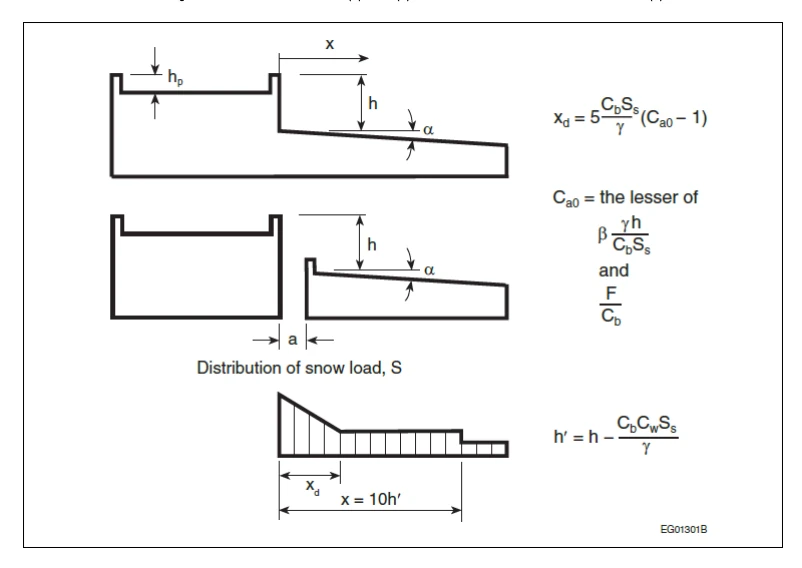
(1)The drifting load of snow on a roof adjacent to a higher roof shall be taken as trapezoidal, as shown in Figure 4.1.6.5.-A, and the accumulation factor, Ca, shall be determined as follows: Ca = Ca0 – (Ca0 – 1)(x/xd), for 0 ≤ x ≤ xd or Ca = 1.0, for x > xd where Ca0 = peak value of Ca at x = 0 as specified in Sentences (3) and (4) and as shown in Figure 4.1.6.5.A., x = distance from roof step as shown in Figure 4.1.6.5.-A, and xd = length of drift as specified in Sentence (2) and as shown in Figure 4.1.6.5.-A.
Notes to Figure 4.1.6.5.-A:
| Distance from Roof Step, x | Factors | ||
|---|---|---|---|
| Cw | Cs(1) | Ca | |
| 0 | 1.0 | f(α) | Ca0 |
| 0 < x ≤ xd | 1.0 | f(α) | Ca0 − (Ca0 − 1)(x/xd) |
| xd < x ≤ 10h’ | 1.0 | f(α) | 1.0 |
| x > 10h’ | 1.0 for unexposed roof areas 0.75 for exposed roof areas 0.5 for exposed roof areas north of tree line | f(α) | 1.0 |
Notes to Table 4.1.6.5.-A:
(2)The length of the drift, xd, shall be calculated as follows: xd = 5 (Cb Ss) / γ (Ca0 −1) where γ = specific weight of snow as specified in Article 4.1.6.13.
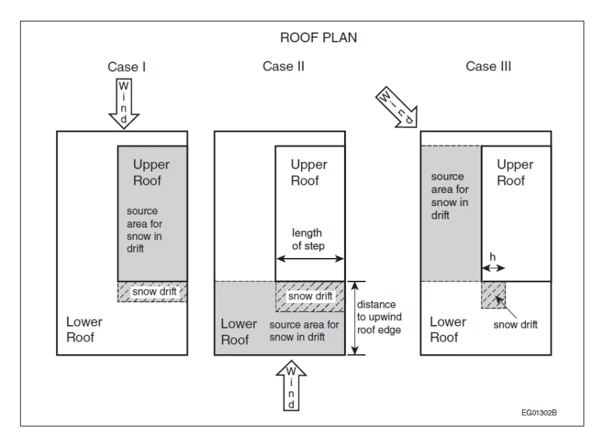
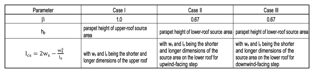
(3)Except as provided in Sentence (4), the value of Ca0 for each of Cases I, II and III shall be the lesser of Ca0 = β γh / (Cb Ss) and Ca0 = F / Cb where β = 1.0 for Case I and 0.67 for Cases II and III, h = difference in elevation between the lower roof surface and the top of the parapet on the upper roof as shown in Figure 4.1.6.5.-A, and F = 0.35β√(γ(lcs −5hp′) / Ss) + Cb, but F ≤ 5 for Cws = 1.0 where Cws = value for Cw applicable to the source of drifting, lcs = characteristic length of the source area for drifting, defined as, lcs = 2ws − ws2 / ls, where ws and ls are respectively the shorter and longer dimensions of the relevant source areas for snow drifting shown in Figure 4.1.6.5.-B for Cases I, II and III, and hp′ = hp −(0.8Ss / γ), but 0 ≤ hp′ ≤ (lcs / 5) where hp = height of the roof perimeter parapet of the source area, to be taken as zero unless all the roof edges of the source area have parapets.
(4)Where h ≥ 5 m, the value of Ca0 for Case I is permitted to be taken as Ca0 = ((25 − h) / 20)(F / Cb −1)+1 for 5 m ≤ h ≤ 25 m, and Ca0 = 1 for h > 25 m
(5)The value of Ca0 shall be the highest of Cases I, II and III, considering the different roof source areas for drifting snow, as specified in Sentences (3) and (4) and Figure 4.1.6.5.-B.
4.1.6.6. Horizontal Gap Between a Roof and a Higher Roof Copy linkAdd bookmark
(1)Where the roof of one building is separated by a distance, a, from an adjacent building with a higher roof as shown in Figure 4.1.6.5.-A, the influence of the adjacent building on the value of the accumulation factor, Ca, for the lower roof shall be determined as follows:
(a)if a > 5 m, the influence of the adjacent building on Ca for the lower roof can be ignored, and
(b)if a ≤ 5 m, Ca for the lower roof shall be calculated in accordance with Article 4.1.6.5. for values of x ≥ a.
4.1.6.7. Areas Adjacent to Roof Projections Copy linkAdd bookmark
(1)Except as provided in Sentences (2) and (3), the accumulation factor, Ca, for areas adjacent to roof-mounted vertical projections shall be calculated in accordance with Sentence 4.1.6.5.(1) using the following values for the peak accumulation factor, Ca0, and the drift length, xd:
(a)Ca0 shall be taken as the lesser of, 0.67 γh / (Cb Ss) and γl0 / (7.5Cb Ss) + 1, and
(b)xd shall be taken as the lesser of 3.35h and (2/3)l0, where h = height of the projection, and l0 = longest horizontal dimension of the projection. (See Note A-4.1.6.7.(1))
(2)Ca is permitted to be calculated in accordance with Article 4.1.6.5. for larger projections. (See Note A-4.1.6.7.(2))
(3)Where the longest horizontal dimension of the roof projection, l0, is less than 3 m, the drift surcharge adjacent to the projection need not be considered.
4.1.6.8. Snow Drift at Corners Copy linkAdd bookmark
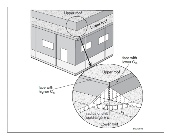
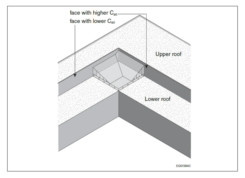
(1)The drift loads on the lower level roof against the two faces of an outside corner of an upper level roof or roof obstruction shall be extended radially around the corner as shown in Figure 4.1.6.8.-A and may be taken as the least severe of the drift loads lying against the two faces of the corner.
(2)The drift loads on the lower level roof against the two faces of an inside corner of an upper level roof or a parapet shall be calculated for each face and the higher of the two loads shall be applied where the drifts overlap as shown in Figure 4.1.6.8.-B.
4.1.6.9. Gable Roofs (See Note A-4.1.6.9.) Copy linkAdd bookmark
(1)For all gable roofs, the full and partial load cases defined in Article 4.1.6.3. shall be considered.
(2)For gable roofs with a slope of α > 15°, the unbalanced load case shall also be considered by setting the values of the accumulation factor, Ca, as follows:
(a)on the upwind side of the roof peak, Ca shall be taken as 0, and
(b)on the downwind side of the roof peak, Ca shall be taken as,
(i)0.25 + α/20, where 15° ≤ α ≤ 20°, and
(ii)1.25, where 20° < α ≤ 90°.
(3)For all gable roofs, the slope factor, Cs, shall be as prescribed in Sentences 4.1.6.2.(5) and (6).
(4)For all gable roofs, the wind exposure factor, Cw, shall be
(a)as prescribed in Sentences 4.1.6.2.(3) and (4) for the full and partial load cases, and
(b)1.0 for the unbalanced load case referred to in Sentence (2).
4.1.6.10. Arch Roofs, Curved Roofs and Domes Copy linkAdd bookmark
(1)For all arch roofs, curved roofs and domes, the full and partial load cases defined in Article 4.1.6.3. shall be considered.
(2)For arch roofs, curved roofs and domes with rise-to-span ratio h/b > 0.05 (See Figure 4.1.6.10.-A), the load cases provided in Sentences (3) to (7) shall also be considered.
(3)For arch roofs with a slope at the edge αe ≤ 30° (See Figure 4.1.6.10.-A and Table 4.1.6.10.), Ca shall be
(a)taken as 0 on the upwind side of the peak, and
(b)on the downwind side of the peak, taken as Ca = xh / (0.03Cb b2) for 0.05 < h / b ≤ 0.12 and Ca = 4x / (Cb b) for h / b > 0.12 where x = horizontal distance from the roof peak, h = height of arch, and b = width of arch.

Notes to Figure 4.1.6.10.-A:
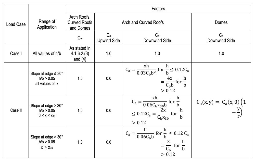
(4)For arch roofs with a slope at the edge αe > 30° (See Figure 4.1.6.10.-A and Table 4.1.6.10.), Ca shall be
(a)taken as 0 on the upwind side of the peak, and
(b)on the downwind side of the peak,
(i)for the part of the roof between the peak and point where the slope α = 30°, taken as, Ca = xh / (0.06Cb x30 b) for 0.05 < h / b ≤ 0.12, and Ca = 2x / (Cb x30) for h / b > 0.12 where x, h, b = as specified in Sentence (2), and x30 = value of x where the slope α = 30°, and
(ii)for the part of the roof where the slope α > 30°, taken as, Ca = h / (0.06Cb b) for 0.05 < h / b ≤ 0.12, and Ca = 2 / Cb for h / b > 0.12
(5)Except as provided in Sentence (6), Ca for curved roofs shall be determined in accordance with the requirements for arch roofs stated in Sentences (3) and (4).
(6)Where the slope, α, of a curved roof at its peak is greater than 10°, Ca shall be determined in accordance with the requirements for gable roofs stated in Article 4.1.6.9. using a slope equal to the mean slope of the curved roof.
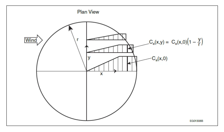
(7)For domes of circular plan form (see Figure 4.1.6.10.-B), Ca shall
(a)along the central axis parallel to the wind, vary in the same way as for an arch roof with the same rise-to-span ratio, h/b, and
(b)off this axis, vary according to Ca (x, y) = Ca (x, 0)(1 − y / r) where Ca(x,y) = value of Ca at location (x,y), Ca(x,0) = value of Ca on the central axis parallel to the wind, x = distance along the central axis parallel to the wind, y = horizontal coordinate normal to the x direction, and r = radius of dome.
(8)For all arch roofs, curved roofs and domes, the slope factor, Cs, shall be as prescribed in Sentences 4.1.6.2.(5) and (6).
Notes to Figure 4.1.6.10.-B:
(9)For all arch roofs, curved roofs and domes, the wind exposure factor, Cw, shall be as prescribed in Table 4.1.6.10.
4.1.6.11. Snow Loads Due to Sliding Copy linkAdd bookmark
(1)Except as provided in Sentence (2), where an upper roof, or part thereof, slopes downwards with a slope α > 0 towards a lower roof, the snow load, S, on the lower roof, determined in accordance with Articles 4.1.6.2. and 4.1.6.5., shall be augmented in accordance with Sentence (3) to account for the additional load resulting from sliding snow.
(2)Sentence (1) need not apply where
(a)snow from the upper roof is prevented from sliding by a parapet or other effective means, or
(b)the upper roof is not considered slippery and has a slope less than 20°.
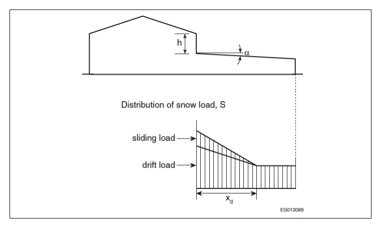
(3)The total weight of additional snow resulting from sliding shall be taken as half the total weight of snow resulting from the uniform load case prescribed in Article 4.1.6.2. with
(a)the accumulation factor Ca = 1.0 for the relevant part of the upper roof,
(b)the slope factor, Cs, based on the slope of the lower roof, as prescribed in Sentences 4.1.6.2.(5) and (6), and
(c)the sliding snow distributed on the lower roof such that it is a maximum for x = 0 and decreases linearly to 0 at x = xd, as shown in Figure 4.1.6.11., where x and xd are as defined in Article 4.1.6.5.
4.1.6.12. Valleys in Curved or Sloped Roofs Copy linkAdd bookmark
(1)For valleys in curved or sloped roofs with a slope α > 10°, in addition to the full and partial load cases defined in Article 4.1.6.3., the non-uniform load Cases II and III presented in Sentences (2) and (3) shall be considered to account for sliding, creeping and movement of meltwater.
(2)For Case II (See Figure 4.1.6.12.), the accumulation factor, Ca, shall be calculated as follows: Ca = 1 / Cb for 0 < x ≤ b / 4, and Ca = 0.5 / Cb for b / 4 < x ≤ b / 2 where x = horizontal distance from the bottom of the valley, and b = twice the horizontal distance between the bottom of the valley and the peak of the roof surface in question.
(3)For Case III (See Figure 4.1.6.12.), Ca shall be calculated as follows: Ca = 1.5 / Cb for 0 < x ≤ b / 8, and Ca = 0.5 / Cb for b / 8 < x ≤ b / 2 where x, b = as specified in Sentence (2).
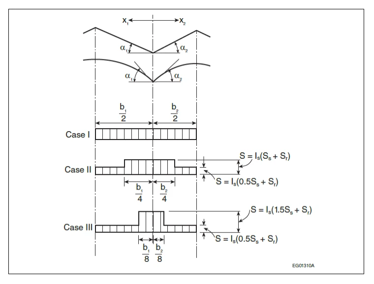
Notes to Figure 4.1.6.12.:
4.1.6.13. Specific Weight of Snow Copy linkAdd bookmark
(1)For the purposes of calculating snow loads in drifts, the specific weight of snow, γ, shall be taken as 4.0 kN/m3 or 0.43SS + 2.2 kN/m3, whichever is lesser.
4.1.6.14. Snow Removal Copy linkAdd bookmark
(1)Snow removal by mechanical, thermal, manual or other means shall not be used as a rationale to reduce design snow loads.
4.1.6.15. Ice Loading of Structures Copy linkAdd bookmark
(1)For lattice structures connected to the building, and other building components or appurtenances involving small width elements subject to significant ice accretion, the weight of ice accretion and the effective area presented to wind shall be as prescribed in CAN/CSA-S37, “Antennas, towers, and antenna-supporting structures.”
4.1.6.16. Roofs with Solar Panels (See Note A-4.1.6.16.) Copy linkAdd bookmark
(1)Where solar panels are installed on a roof, the snow loads, S, shall be determined in accordance with Sentences (2) to (6) or with the requirements for roofs without solar panels, whichever produces the most critical effect.
(2)For the purposes of this Article, solar panels shall be classified as
(a)Parallel Flush, where the panels are installed parallel to the roof surface with their upper surface less than or equal to CbCwSs/γ above the roof surface,
(b)Parallel Raised, where the panels are installed parallel to the roof surface with their upper surface greater than CbCwSs/γ above the roof surface, or
(c)Tilted, where the panels are installed at an angle to the roof surface with their highest edge greater than CbCwSs/γ above the roof surface.
(3)For sloped roofs with solar panels, the snow loads, S, shall be determined in accordance with the requirements for roofs without solar panels, except that the slope factor, Cs, shall be
(a)taken as 1.0 for roof areas extending upslope from the downslope edge of a panel or array of panels at an angle of 45° from each side edge of the panel or array, and
(b)as specified in Sentences 4.1.6.2.(5) to (7) for all other roof areas.
(See Note A-4.1.6.16.(3))
(4)For sloped roofs with Parallel Flush solar panels, the snow loads, S, shall be determined in accordance with the requirements for roofs without solar panels, except that
(a)Cs shall be determined in accordance with Sentence (3),
(b)where the gap width, wg, between the panels along the roof slope is greater than or equal to the panel width, wp, along the roof slope, the accumulation factor, Ca, shall be taken as
(i)0.0 for the panels,
(ii)2.0 for roof areas within a distance of wp downslope from a downslope panel edge, and
(iii)1.0 for all other roof areas, and (See Note A-4.1.6.16.(4)(b))
(c)where the gap width, wg, between the panels along the roof slope is less than the panel width, wp, along the roof slope, Ca shall be taken as
(i)0.0 for panel areas within a distance of wg downslope from an upslope panel edge,
(ii)1.0 for other panel areas,
(iii)2.0 for roof areas in gaps between the panels, and
(iv)1.0 for all other roof areas.
(See Note A-4.1.6.16.(4)(c))
(5)For roofs with Parallel Raised solar panels, the snow loads, S, shall be determined in accordance with the requirements for roofs without solar panels, except that
(a)where the roof is flat, Ca shall be taken as
(i)1.0 for the panels,
(ii)1.0 for roof areas not under the panels,
(iii)1.0 for roof areas under the panels within a distance of min (2hg,2wg) from a panel edge, where hg is the gap height between the lower surface of the panels and the roof surface, and wg is the gap width between the panels, and
(iv)0.0 for other roof areas under the panels, and
(See Note A-4.1.6.16.(5)(a))
(b)where the roof is sloped, the snow loads, S, derived from Clause (a) shall be used, except that
(i)Cs shall be determined in accordance with Sentence (3),
(ii)S shall be taken as 0.0 on the panels, and
(iii)S for all roof areas shall be taken as the sum of S on the panels, as derived from Subclause (a)(i) and shifted by a distance of wp downslope onto the roof, where wp is the panel width along the roof slope, and S on the roof areas, as derived from Subclauses (a)(ii) to (a)(iv).
(See Note A-4.1.6.16.(5)(b))
(6)For flat roofs with Tilted solar panels, the snow loads, S, shall be determined in accordance with the requirements for roofs without solar panels, except that
(a)Ca shall be taken as 0.0 for the panels,
(b)Ca shall be taken as 1.0 for roof areas beyond a distance of 5(h – CbCwSs/γ) from the lowest edge of the panels, where h is the height of the highest edge of the panels above the roof surface,
(c)except as provided in Clauses (d) and (e), for roof areas within a distance of 5(h – CbCwSs/γ) from the lowest edge of the panels, Ca shall be taken as
(i)1.25 for (hg – CbCwSs/γ) ≤ 0.3 m, where hg is the gap height between the lowest edge of the panels and the roof surface,
(ii)1.294 – 0.1471(hg – CbCwSs/γ) for 0.3 < (hg – CbCwSs/γ) ≤ 2.0 m, and
(iii)1.0 for (hg – CbCwSs/γ) > 2.0 m,
(See Note A-4.1.6.16.(6)(c))
(d)except as provided in Clause (e), Ca shall be taken as 2.0 for roof areas within a distance of wph beyond the lowest edge of the panels, where wph is the horizontal projection of the panel width, wp, along the sloped panel edges, and
(e)where the panels, panel supports or back plates obstruct snow from sliding under the panels, the load of the increased volume of snow in the gaps between the panels shall be considered to be uniformly distributed.
(See Note A-4.1.6.16.(6))