Division B
Part 7 - Plumbing
Section 7.1. General Copy linkAdd bookmark
7.0.1. Scope Copy linkAdd bookmark
7.0.1.1. Scope Copy linkAdd bookmark
(1)The scope of this Part shall be as described in Subsection 1.3.3. of Division A.
7.1.1. Application Copy linkAdd bookmark
7.1.1.1. Application Copy linkAdd bookmark
(1)Except as provided in Sentence (2), this Part applies to the design and construction of plumbing.
(2)This Part does not apply to industrial process systems unless the industrial process system is interconnected with the plumbing system, in which case the interconnection shall be so designed and installed so that the plumbing system is protected against contamination or malfunction that may be caused by the industrial system.
7.1.1A. Definitions Copy linkAdd bookmark
7.1.1A.1. Definitions Copy linkAdd bookmark
(1)Except as provided in Sentence (2), words that appear in italics are defined in Article 1.4.1.2. of Division A and in the Building Code Act, 1992.
(2)In this Part,
- Storey means the interval between two successive floor levels including mezzanine floors that contain plumbing fixtures or between a floor level and roof.
7.1.1B. Plumbing Facilities Copy linkAdd bookmark
7.1.1B.1. Facilities Required Copy linkAdd bookmark
(1)Plumbing facilities shall be provided in accordance with Subsection 3.7.4. and Section 9.31.
7.1.1B.2. Floor Drains Copy linkAdd bookmark
(1)Where gravity drainage to a sanitary drainage system is possible, a floor drain shall be installed in a basement forming part of a dwelling unit.
(2)Where gravity drainage to a sanitary drainage system is not possible, the floor drain required by Sentence (1) may be connected to a storm drainage system, dry well or drainage ditch provided it is located where it can receive only clear water waste or storm sewage.
(3)A floor drain shall be provided in a public laundry room, garbage room, incinerator room, boiler or heating room that is not located within a dwelling unit.
7.1.2. Service Connections Copy linkAdd bookmark
7.1.2.1. Sanitary Drainage Systems Copy linkAdd bookmark
(1)Except as provided in Sentence 7.2.2.3.(2), sanitary drainage systems shall be connected to a public sanitary sewer, a public combined sewer or a private sewage disposal system.
(2)A combined building drain or a combined building sewer shall not be installed. (See Note A-7.1.2.1.(2))
7.1.2.2. Storm Drainage Systems Copy linkAdd bookmark
(1)Except as provided in Sentences 7.2.2.3.(2) and (3), storm drainage systems and private sewers conveying storm sewage shall be connected to a public storm sewer, a public combined sewer or a designated storm water disposal location.
7.1.2.3. Water Distribution Systems Copy linkAdd bookmark
(1)Except as provided in Section 7.7. and Sentence (2), water distribution systems shall be connected to a public water main, drinking water system or a potable private water supply system.
(2)Storm sewage or greywater that is free of solids and treated to conform to Article 7.7.4.1. is permitted to be used as a water supply for
(a)water closets,
(b)urinals,
(c)sub-surface irrigation, or
(d)the priming of traps.
(3)Rainwater that is free of solids and treated to conform to Article 7.7.4.1. is permitted to be used as a water supply for
(a)clothes washers,
(b)laundry trays,
(c)mop sinks,
(d)bedpan washers,
(e)water closets,
(f)urinals,
(g)hose bibbs,
(h)sub-surface irrigation, or
(i)the priming of traps.
(4)Piping conveying the non-potable water described in Sentence (2) shall be installed in conformance with Section 7.7.
7.1.2.4. Separate Services Copy linkAdd bookmark
(1)Except as provided in Sentences (2) and (3), piping in any building connected to the public services shall be connected separately from piping of any other building, except that an ancillary building on the same property may be served by the same service. (See Note A-7.1.2.4.(1))
(2)No plumbing serving a dwelling unit shall be installed in or under another unit of the building unless the piping is located in a tunnel, pipe corridor, common basement or parking garage, so that the piping is accessible for servicing and maintenance throughout its length without encroachment on any private living space, but this Sentence does not prevent plumbing serving a unit located above another unit from being installed in or under the lower unit.
(3)Water service pipes or building sewers serving buildings located on the same property may connect into a private water supply or a private sewer conforming to Article 7.1.2.5.
7.1.2.5. Private Sewers and Private Water Supply Copy linkAdd bookmark
(1)Private water supply pipes shall be designed and installed according to MOE PIBS 6881e, “Design Guidelines for Drinking-Water Systems”.
(2)Private sewers shall be designed and installed according to MOE PIBS 6879, “Design Guidelines for Sewage Works”.
7.1.3. Location of Fixtures Copy linkAdd bookmark
7.1.3.1. Lighting and Ventilation Requirements Copy linkAdd bookmark
(1)Plumbing fixtures shall not be installed in a room that is not lighted and ventilated in accordance with the appropriate requirements in Parts 3, 6 and 9.
7.1.3.2. Accessibility Copy linkAdd bookmark
(1)Every fixture, plumbing appliance, interceptor, cleanout, valve, device or piece of equipment shall be located so that it is readily accessible for use, cleaning and maintenance.
7.1.3A. Accommodating Movement Copy linkAdd bookmark
7.1.3A.1. Structural Movement Copy linkAdd bookmark
(1)Plumbing shall be designed and installed to accommodate the maximum relative structural movement provided for in the construction of the building.
7.1.4. Seismic Design Copy linkAdd bookmark
7.1.4.1. Seismic Restraints and Design Copy linkAdd bookmark
(1)Plumbing systems in buildings constructed in accordance with Part 3 shall be designed and installed to accommodate the seismic forces addressed in Subsection 4.1.8. (See Note A-7.1.4.1.(1))
Section 7.2. Materials and Equipment Copy linkAdd bookmark
7.2.1. General Copy linkAdd bookmark
7.2.1.1. Exposure of Materials Copy linkAdd bookmark
(1)Where unusual conditions exist such as excessively corrosive soil or water, only materials suited for use in such locations shall be used.
(2)Materials and equipment used in a drainage system where excessively corrosive wastes are present shall be suitable for the purpose.
7.2.1.2. Restrictions on Re-Use Copy linkAdd bookmark
(1)Materials and equipment that have been used for a purpose other than the distribution of potable water shall not be subsequently used in a potable water system.
(2)Used materials and equipment, including fixtures, shall not be reused unless they meet the requirements of this Part for new materials and equipment and are otherwise satisfactory for their intended use.
7.2.1.3. Identification Copy linkAdd bookmark
(1)Every length of pipe and every fitting shall
(a)have cast, stamped or indelibly marked on it the maker's name or mark and the weight or class or quality of the product, or
(b)be marked in accordance with the relevant standard.
(2)Markings required in Sentence (1) shall be visible after installation.
(3)The lack of certification markings on a product or plumbing component shall be regarded as proof, in the absence of evidence to the contrary, that no certification exists.
(4)If a component of a plumbing system is required to be certified to a standard, the certification shall be made by a testing agency accredited for that purpose by the Standards Council of Canada.
7.2.1.4. Pipe or Piping Copy linkAdd bookmark
(1)Where the term pipe or piping and fittings is used, it shall also apply to tube or tubing and fittings unless otherwise stated.
7.2.1.5. Withstanding Pressure Copy linkAdd bookmark
(1)Piping, fittings and joints used in pressure sewer, forcemain or sump pump discharge applications shall be capable of withstanding at least one and one-half times the maximum potential pressure.
7.2.1.6. Working Pressure of a Water Service Pipe Copy linkAdd bookmark
(1)The working pressure rating of a water service pipe shall not be less than the maximum water main pressure at their point of connection as established by the water supply authority.
7.2.2. Fixtures Copy linkAdd bookmark
7.2.2.1. Surface Requirements Copy linkAdd bookmark
(1)Every fixture shall have a smooth, hard, corrosion-resistant surface free of flaws and blemishes that may interfere with cleaning.
7.2.2.2. Conformance to Standards Copy linkAdd bookmark
(0.1)Water closets and urinals shall conform to the requirements in Article 7.6.1.6.
(1)Except as provided in Article 7.2.2.3.,
(a)reserved,
(b)vitreous china fixtures shall conform to ASME A112.19.2 / CSA B45.1, “Ceramic Plumbing Fixtures,”
(c)enamelled cast-iron fixtures shall conform to ASME A112.19.1 / CSA B45.2, “Enamelled Cast Iron and Enamelled Steel Plumbing Fixtures,”
(d)porcelain-enamelled steel fixtures shall conform to ASME A112.19.1 / CSA B45.2, “Enamelled Cast Iron and Enamelled Steel Plumbing Fixtures,”
(e)stainless steel fixtures shall conform to ASME A112.19.3 / CSA B45.4, “Stainless Steel Plumbing Fixtures,”
(f)plastic fixtures shall conform to CSA B45.5 / IAPMO Z124, “Plastic plumbing fixtures,”
(g)hydromassage bathtubs shall conform to ASME A112.19.7 / CSA B45.10, “Hydromassage Bathtub Systems,”
(h)macerating toilet systems shall conform to ASME A112.3.4 / CSA B45.9, “Macerating Toilet Systems and Waste-Pumping Systems for Plumbing Fixtures,” and
(i)personal hygiene devices for water closets shall conform to ASME A112.4.2 / CSA B45.16, “Personal hygiene devices for water closets.”
7.2.2.3. Showers Copy linkAdd bookmark
(1)Shower receptors shall be constructed and arranged so that water cannot leak through the walls or floor. (See Note A-7.2.2.3.(1))
(2)Not more than 6 shower heads shall be served by a single shower drain.
(3)Where 2 or more shower heads are served by a shower drain, the floor shall be sloped and the drain located so that water from one head cannot flow over the area that serves another head.
(4)Except for column showers, when a battery of shower heads is installed, the horizontal distance between 2 adjacent shower heads shall be not less than 750 mm.
7.2.2.4. Concealed Overflows Copy linkAdd bookmark
(1)A dishwashing sink and a food preparation sink shall not have concealed overflows. (See Note A-7.2.2.4.(1))
7.2.2.5. Water Closets in Public Washrooms Copy linkAdd bookmark
(1)Except for Eastern-Style toilets, where a water closet is installed in a washroom for public use it shall be of the elongated type and provided with a seat of the open front type.
7.2.2.6. Lavatories Copy linkAdd bookmark
(1)A lavatory that does not have an overflow shall be equipped with a centre outlet waste fitting. (See Note A-7.2.2.6.(1))
7.2.2.7. Trough Urinals Copy linkAdd bookmark
(1)No trough urinal shall be used as part of a plumbing system.
7.2.3. Traps and Interceptors Copy linkAdd bookmark
7.2.3.1. Traps Copy linkAdd bookmark
(1)Except as provided for in Sentence (2), traps shall
(a)have a trap seal depth of not less than 38 mm,
(b)be so designed that failure of the seal walls will cause exterior leakage, and
(c)have a water seal that does not depend on the action of moving parts.
(See Note A-7.2.3.1.(1) and (3))
(2)The trap seal depth on fixtures draining to an acid waste system shall be a minimum of 50 mm.
(3)Except for a floor-mounted service sink, every trap that serves a lavatory, a sink or a laundry tray shall
(a)be provided with a cleanout plug located at the lowest point of the trap and of the same material as the trap, except that a cast iron trap shall be provided with a brass cleanout plug, or
(b)be designed so that part of the trap can be removed for cleaning purposes.
(See Note A-7.2.3.1.(1) and (3))
(4)A bell trap shall not be installed in a drainage system.
(5)A drum trap shall not be installed in a drainage system.
(6)Except as permitted in Sentence (7), no bottle trap shall be used in a plumbing system.
(7)A bottle trap may be used on a laboratory sink or other fixture equipped with corrosion resistant fittings.
(8)No running trap shall be installed in a plumbing system unless an accessible handhole is provided for cleaning of the trap, and where the trap is too small to accommodate a handhole, a cleanout shall be provided.
7.2.3.2. Interceptors Copy linkAdd bookmark
(1)Interceptors shall be designed so that they can be readily cleaned.
(2)Grease interceptors shall be designed so that they do not become air bound.
(3)Grease interceptors shall be selected and installed in conformance with
(a)CSA B481.0, “Material, design, and construction requirements for grease interceptors,” and
(b)CSA B481.3, “Sizing, selection, location, and installation of grease interceptors.”
(See Note A-7.2.3.2.(3))
(4)Where a grease interceptor is required by Sentence 7.4.4.3.(1), the interceptor shall conform to
(a)CSA B481.1, “Testing and rating of grease interceptors using lard,” or
(b)CSA B481.2, “Testing and rating of grease interceptors using oil.”
7.2.3.3. Tubular Traps Copy linkAdd bookmark
(1)Tubular metal or plastic traps that conform to ASME A112.18.2 / CSA B125.2, “Plumbing Waste Fittings” shall be used only in accessible locations.
7.2.4. Pipe Fittings Copy linkAdd bookmark
7.2.4.1. T and Cross Fittings Copy linkAdd bookmark
(1)A T fitting shall not be used in a drainage system except to connect a vent pipe.
(2)A cross fitting shall not be used in a drainage system.
7.2.4.2. Sanitary T Fittings Copy linkAdd bookmark
(1)A double sanitary T fitting shall not be used to connect the fixture drains of two urinals where no cleanout fitting is provided above the connection.
(2)No pipe fitting, joint or connection that would tend to intercept solids or reduce the flow through a pipe by more than 10 percent shall be used in a plumbing system.
7.2.4.3. 90° Elbows Copy linkAdd bookmark
(1)Except as permitted in Sentences (2) and (3), 90° elbows of NPS 4 or less whose centre-line radius that is less than the NPS of the pipe shall not be used to join 2 sanitary drainage pipes.
(2)For sanitary drainage systems of NPS 4 or less, 90° elbows described in Sentence (1) shall only be permitted
(a)to change the direction of piping from horizontal to vertical, in the direction of flow,
(b)where a trap arm enters a wall, or
(c)to connect trap arms as permitted by Sentence 7.5.6.3.(2).
(3)A 90° elbow that is part of the pre-engineered wastewater heat recovery system is permitted to have a centre-line radius that is less than the size of the pipe.
7.2.4.4. Fittings Restricted in Use Copy linkAdd bookmark
(1)No double Y, double TY, double T or double waste fitting shall be installed in a nominally horizontal soil or waste pipe.
7.2.4.5. Assembled Pipe or Tubing Copy linkAdd bookmark
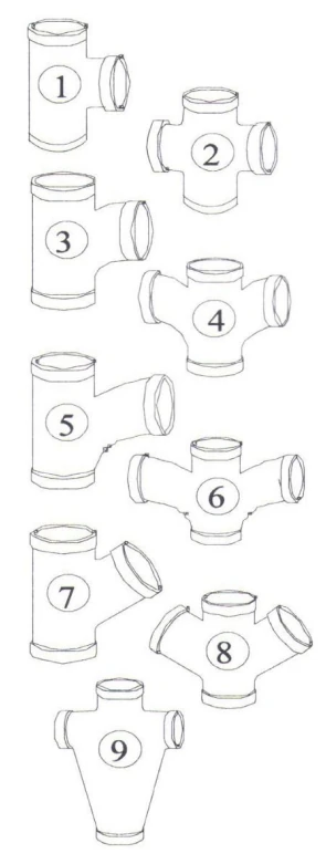
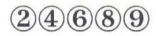
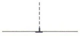
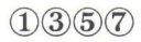
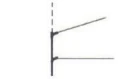
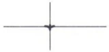
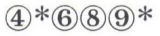
(1)Pipe or tubing assembled to comprise a standard drain waste and venting system shall be connected with drain, waste and vent fittings in conformance with Table 7.2.4.5.
| Pipe Arrangement | Fittings | ||
|---|---|---|---|
| Acceptable | Type | ||
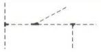 | 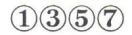 |  | |
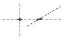 |  | ||
 |  | ||
 |  | ||
 |  | ||
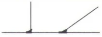 |  | ||
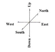 | LEGEND (DWV BRANCH FITTINGS) Vent pipe – – – – – – – – – – – Drainage pipe —————————— * Acceptable only if vertical run is of 3 inches size or larger and horizontal branches are of 11/4, 11/2, or 2 inches size | ||
| 1. Straight T 2. Double T or Cross 3. Sanitary T or Short Turn TY 4. Double Sanitary T or Short Turn Double TY 5. Combination Y & 1/8 Bend or Long Turn TY | 6. Double Combination Y & 1/8 Bend or Double Long Turn TY 7. Y 8. Double Y 9. Double Waste Fitting | ||
7.2.5. Non-Metallic Pipe and Fittings Copy linkAdd bookmark
7.2.5.1. Fibrocement Pipe and Fittings Copy linkAdd bookmark
(1)Fibrocement pipe and fittings for use in a drain, waste or vent system shall conform to CAN/CSA-B127.3, “Fibrocement drain, waste, and vent pipe and pipe fittings.”
7.2.5.2. Concrete Pipe and Fittings Copy linkAdd bookmark
(1)Concrete pipe shall conform to
(a)CSA A257.1, “Non-reinforced circular concrete culvert, storm drain, sewer pipe, and fittings,” or
(b)CSA A257.2, “Reinforced circular concrete culvert, storm drain, sewer pipe, and fittings.”
(2)Joints with internal elastomeric gaskets shall conform to CSA A257.3, “Joints for circular concrete sewer and culvert pipe, manhole sections, and fittings using rubber gaskets.”
(3)Concrete fittings fabricated on the site from lengths of pipe shall not be used. (See Note A-7.2.5.2.(3))
(4)Concrete pipe shall not be used above ground inside a building.
(5)Precast reinforced circular concrete manhole sections, catch basins and fittings shall conform to CSA A257.4, “Precast reinforced circular concrete manhole sections, catch basins, and fittings.”
7.2.5.3. Vitrified Clay Pipe and Fittings Copy linkAdd bookmark
(1)Vitrified clay pipe and fittings shall be certified to CSA A60.1-M, “Vitrified Clay Pipe.”
(2)Couplings and joints for vitrified clay pipe shall be certified to CSA A60.3-M, “Vitrified Clay Pipe Joints.”
(3)Vitrified clay pipe and fittings shall not be used except for an underground part of a drainage system.
7.2.5.4. Polyethylene Pipe and Fittings Copy linkAdd bookmark
(1)Polyethylene water pipe, tubing and fittings shall conform to, and have a pressure rating meeting the requirements of, Series 160 or a higher series of CSA B137.1, “Polyethylene (pe) pipe, tubing and fittings for cold water pressure services.”
(2)Except as permitted in Sentence 7.2.5.6.(1), polyethylene water pipe shall not be used except for a water service pipe.
(3)Butt fusion fittings for polyethylene pipe shall conform to ASTM D3261, “Standard Specification for Butt Heat Fusion Polyethylene (PE) Plastic Fittings for Polyethylene (PE) Plastic Pipe and Tubing.”
7.2.5.5. Polyethylene Pipe Used Underground Copy linkAdd bookmark
(1)Polyethylene pipe used underground in a drainage system for rehabilitation of existing systems using trenchless technology shall conform to ASTM F714, “Standard Specification for Polyethylene (PE) Plastic Pipe (DR-PR) Based on Outside Diameter” and shall be HDPE 3408, SDR 17 or heavier. (See Note A-7.2.5.5.(1))
7.2.5.6. Crosslinked Polyethylene Pipe and Fittings Copy linkAdd bookmark
(1)Crosslinked polyethylene pipe and manufacturer-approved fittings used in hot and cold potable water systems shall conform to CSA B137.5, “Crosslinked polyethylene (PEX) tubing systems for pressure applications.” (See Note A-7.2.5.6.(1))
7.2.5.7. PVC Pipe and Fittings Copy linkAdd bookmark
(1)PVC water pipe, fittings and solvent cement shall
(a)conform to CSA B137.3, “Rigid Polyvinylchloride (PVC) pipe and fittings for pressure applications” or CSA B137.2, “Polyvinylchloride (PVC) injection-moulded gasketed fittings for pressure applications,” and
(b)a pressure rating of not less than 1 100 kPa.
(2)PVC water pipe fittings shall conform to
(a)ASTM D2466, “Standard Specification for Poly(Vinyl Chloride) (PVC) Plastic Pipe Fittings, Schedule 40,” or
(b)ASTM D2467, “Standard Specification for Poly(Vinyl Chloride) (PVC) Plastic Pipe Fittings, Schedule 80.”
7.2.5.8. CPVC Pipe, Fittings and Solvent Cements Copy linkAdd bookmark
(1)CPVC hot and cold water pipe, fittings and solvent cements shall be conform to CSA B137.6, “Chlorinated polyvinylchloride (CPVC) pipe, tubing and fittings for hot and cold water distribution systems.”
(2)The design temperature and design pressure of a CPVC piping system shall conform to Table 7.2.5.8.
| Maximum Temperature of Water, °C | Maximum Permitted Pressures, kPa |
|---|---|
| 10 | 3150 |
| 20 | 2900 |
| 30 | 2500 |
| 40 | 2100 |
| 50 | 1700 |
| 60 | 1300 |
| 70 | 1000 |
| 82 | 690 |
7.2.5.9. Plastic Pipe, Fittings and Solvent Cement Used Underground (See Note A-7.2.5.9. to 7.2.5.11.) Copy linkAdd bookmark
(1)Plastic pipe, fittings and solvent cement used underground outside a building or under a building in a drainage system shall conform to
(a)ASTM F628, “Standard Specification for Acrylonitrile-Butadiene-Styrene (ABS) Schedule 40 Plastic Drain, Waste, and Vent Pipe With a Cellular Core,”
(b)CSA B181.1, “Acrylonitrile-butadiene-styrene (ABS) drain, waste, and vent pipe and pipe fittings,”
(c)CSA B181.2, “Polyvinylchloride (PVC) and chlorinated polyvinylchloride (CPVC) drain, waste, and vent pipe and pipe fittings,”
(d)CSA B182.1, “Plastic drain and sewer pipe and pipe fittings,”
(e)CSA B182.2, “PSM type polyvinylchloride (PVC) sewer pipe and fittings,”
(f)CSA B182.4, “Profile polyvinylchloride (PVC) sewer pipe and fittings,”
(g)CSA B182.6, “Profile polyethylene (PE) sewer pipe and fittings for leak-proof sewer applications,” or
(h)CSA B182.8, “Profile polyethylene (PE) storm sewer and drainage pipe and fittings,” for Type 1 joints and non-perforated pipes,”
(i)CSA B137.2, “Polyvinylchloride (PVC) injection-moulded gasketed fittings for pressure applications”, or
(j)CSA B137.3, “Rigid polyvinylchloride (PVC) pipe and fittings for pressure applications”.
(2)Except as permitted in Clauses (i) and (j), plastic pipe used as described in Sentence (1) shall have a stiffness equal or greater than 320 kPa.
7.2.5.10. Transition Solvent Cement (See Note A-7.2.5.9. to 7.2.5.11.) Copy linkAdd bookmark
(1)Solvent cement for transition joints shall conform to
(a)CSA B181.1, “Acrylonitrile-butadiene-styrene (ABS) drain, waste, and vent pipe and pipe fittings,” or
(b)CSA B181.2, “Polyvinylchloride (PVC) and chlorinated polyvinylchloride (CPVC) drain, waste, and vent pipe and pipe fittings.”
(2)Transition solvent cement shall only be used for joining an ABS drainage system to a PVC drainage system.
7.2.5.11. Plastic Pipe, Fittings and Solvent Cement Used in Buildings (See Note A-7.2.5.9. to 7.2.5.11) Copy linkAdd bookmark
(1)Plastic pipe, fittings and solvent cement used inside or under a building in a sanitary drainage system or venting system shall conform to
(a)ASTM F628, “Standard Specification for Acrylonitrile-Butadiene-Styrene (ABS) Schedule 40 Plastic Drain, Waste, and Vent Pipe With a Cellular Core,”
(b)CSA B181.1, “Acrylonitrile-butadiene-styrene (ABS) drain, waste, and vent pipe and pipe fittings,” or
(c)CSA B181.2, “Polyvinylchloride (PVC) and chlorinated polyvinylchloride (CPVC) drain, waste, and vent pipe and pipe fittings.”
(1.1)Plastic pipe, fittings and solvent cement used inside a building in a storm drainage system shall conform to
(a)ASTM F628, “Standard Specification for Acrylonitrile-Butadiene-Styrene (ABS) Schedule 40 Plastic Drain, Waste, and Vent Pipe With a Cellular Core,”
(b)CSA B181.1, “Acrylonitrile-butadiene-styrene (ABS) drain, waste, and vent pipe and pipe fittings,”
(c)CSA B181.2, “Polyvinylchloride (PVC) and chlorinated polyvinylchloride (CPVC) drain, waste, and vent pipe and pipe fittings,”
(d)CSA B182.1, “Plastic drain and sewer pipe and pipe fittings,” or
(e)CSA B182.2, “PSM type polyvinylchloride (PVC) sewer pipe and fittings.”
(1.2)Plastic pipe used as described in Sentence (2) shall have a pipe stiffness equal or greater than 320 kPa.
(2)Requirements for combustible piping in relation to fire safety shall conform to Sentences 3.1.5.19.(1) and 9.10.9.8.(3), (5) and (6), and Articles 3.1.9.4., 9.10.9.7. and 9.10.9.9.
(3)Where noncombustible piping pierces a fire separation or a fire block, the requirements for fire stopping of Subsection 3.1.9., Sentence 9.10.9.6.(1) and Article 9.10.16.4. shall apply.
7.2.5.12. Polyethylene/Aluminum/Polyethylene Composite Pipe and Fittings Copy linkAdd bookmark
(1)PE/AL/PE composite pipe and fittings used for potable water systems shall conform to CSA B137.9, “Polyethylene/aluminum/polyethylene (PE-AL-PE) composite pressure-pipe systems.” (See Note A-7.2.5.12.(1))
(2)Except as provided in Sentences (3) and (4), PE/AL/PE pipe and fittings shall not be used in hot water systems.
(3)PE/AL/PE pipe with a pressure rating of 690 kPa or greater at 82ºC shall be permitted for hot water systems.
(4)PE/AL/PE pipe with a pressure rating of 690 kPa or greater at 82ºC shall be used with fittings that conform to CSA B137.10, “Crosslinked polyethylene/aluminum/crosslinked polyethylene (PEX-AL-PEX) composite pressure-pipe systems,” in hot water systems.
7.2.5.13. Crosslinked Polyethylene/Aluminum/Crosslinked Polyethylene Composite Pressure Pipe and Fittings Copy linkAdd bookmark
(1)PEX/AL/PEX composite pipe and fittings used in hot and cold potable water systems shall conform to CSA B137.10, “Crosslinked polyethylene/aluminum/crosslinked polyethylene (PEX-AL-PEX) composite pressure-pipe systems.” (See Note A-7.2.5.13.(1))
7.2.5.14. Polypropylene Pipe and Fittings Copy linkAdd bookmark
(1)Polypropylene pipe and fittings used for hot and cold potable water systems shall conform to CSA B137.11, “Polypropylene (PP-R) pipe and fittings for pressure applications.” (See Note A-7.2.5.14.(1))
7.2.5.15. Polyethylene of Raised Temperature Tube and Fittings Copy linkAdd bookmark
(1)Polyethylene of raised temperature (PE-RT) tube and manufacturer-approved fittings used in hot and cold potable water systems shall conform to CSA B137.18, “Polyethylene of raised temperature resistance (PE-RT) tubing systems for pressure applications.” (See Note A-7.2.5.15.(1))
(2)The use of PE-RT tube shall conform to Table 7.2.5.15.
| Type of Tube | Plumbing Purposes(1) | ||||||||
|---|---|---|---|---|---|---|---|---|---|
| Drainage System | Building Sewer | Venting System | Potable Water System | ||||||
| Aboveground inside building | Underground under building | Above-ground | Under-ground | Cold | Hot | Under building | Outside building | ||
| PE-RT | N | N | N | N | N | P | P | P | P |
Notes to Table 7.2.5.15.:
7.2.5.16. Cellular Core PVC Pipe and Fittings Copy linkAdd bookmark
(1)Cellular core PVC pipe shall
(a)conform to ASTM F3128, “Standard Specification for Poly(Vinyl Chloride) (PVC) Schedule 40 Drain, Waste, and Vent Pipe with a Cellular Core,” and
(b)be light grey, as specified in CSA B181.2, “Polyvinylchloride (PVC) and chlorinated polyvinylchloride (CPVC) drain, waste, and vent pipe and pipe fittings.”
(2)Fittings and solvent cements for cellular core PVC pipe shall conform to CSA B181.2, “Polyvinylchloride (PVC) and chlorinated polyvinylchloride (CPVC) drain, waste, and vent pipe and pipe fittings.”
(3)Cellular core PVC pipe shall only be used in residential buildings containing 1 or 2 dwelling units and in row houses that do not exceed 3 storeys in height.
7.2.6. Ferrous Pipe and Fittings Copy linkAdd bookmark
7.2.6.1. Cast-Iron Drainage and Vent Pipe and Fittings Copy linkAdd bookmark
(1)Drainage piping, vent piping and fittings made of cast iron shall conform to CSA B70, “Cast iron soil pipe, fittings, and means of joining.”
(2)Cast-iron soil pipe and fittings shall not be used in a water system.
7.2.6.2. Maintenance Holes and Catch Basins Copy linkAdd bookmark
(1)Cast-iron frames and covers for maintenance holes and catch basins shall conform to CSA B70.1, “Frames and Covers for Maintenance Holes and Catchbasins.”
7.2.6.3. Threaded Cast-Iron Drainage Fittings Copy linkAdd bookmark
(1)Threaded cast-iron drainage fittings shall conform to ASME B16.12, “Cast Iron Threaded Drainage Fittings.”
(2)Threaded cast-iron drainage fittings shall not be used in a water system.
7.2.6.4. Cast-Iron Water Pipes Copy linkAdd bookmark
(1)Cast-iron water pipes shall conform to ANSI/AWWA C151 / A21.51, “Ductile-Iron Pipe, Centrifugally Cast.”
(2)Cement mortar lining for cast-iron water pipes shall conform to ANSI/AWWA C104 / A21.4, “Cement-Mortar Lining for Ductile-Iron Pipe and Fittings.”
(3)Cast-iron fittings for cast-iron or ductile-iron water pipes shall conform to ANSI/AWWA C110 / A21.10, “Ductile-Iron and Gray-Iron Fittings.”
(4)Rubber gasket joints for cast-iron and ductile-iron pressure pipe for water shall conform to ANSI/AWWA C111 / A21.11, “Rubber-Gasket Joints for Ductile-Iron Pressure Pipe and Fittings.”
7.2.6.5. Screwed Cast-Iron Water Fittings Copy linkAdd bookmark
(1)Screwed cast-iron water fittings shall conform to ASME B16.4, “Gray Iron Threaded Fittings: Classes 125 and 250.”
(2)Screwed cast-iron water fittings used in a water system shall be cement-mortar lined or galvanized.
(3)Screwed cast iron water fittings shall not be used in a drainage system.
7.2.6.6. Screwed Malleable-Iron Water Fittings Copy linkAdd bookmark
(1)Screwed malleable-iron water fittings shall conform to ASME B16.3, “Malleable Iron Threaded Fittings: Classes 150 and 300.”
(2)Screwed malleable-iron water fittings used in a water system shall be cement-mortar lined or galvanized.
(3)Screwed malleable-iron water fittings shall not be used in a drainage system.
7.2.6.7. Steel Pipe Copy linkAdd bookmark
(1)Except as provided in Sentences (2) and (3), welded and seamless steel pipe shall not be used in a plumbing system.
(2)Galvanized steel pipe is permitted to be used in a drainage system or a venting system above ground inside a building.
(3)Galvanized steel pipe and fittings shall not be used in a water distribution system except
(a)in buildings of industrial occupancy, or
(b)for the repair of existing galvanized steel piping systems.
(See Note A-7.2.6.7.(3))
(4)Galvanized steel pipe and fittings shall conform to ASTM A53 / A53M, “Standard Specification for Pipe, Steel, Black and Hot Dipped, Zinc-Coated Welded and Seamless.”
(5)Where galvanized steel pipe is used in a drainage system, it shall be used with drainage fittings.
(6)All steel pipe of NPS 4 and smaller shall be Schedule 40 or heavier and fittings of less than NPS 2 shall be galvanized screw fittings.
7.2.6.8. Corrugated Steel Pipe and Couplings Copy linkAdd bookmark
(1)Corrugated steel pipe and couplings shall conform to CAN/CSA-G401, “Corrugated steel pipe products”.
(2)Corrugated steel pipe shall only be used underground outside a building in a storm drainage system.
(3)Couplings for corrugated steel pipe shall be constructed so that when installed they shall
(a)maintain the pipe alignment,
(b)resist the separation of adjoining lengths of pipe,
(c)prevent root penetration, and
(d)prevent the infiltration of surrounding material.
7.2.6.9. Sheet Metal Leaders Copy linkAdd bookmark
(1)A sheet metal leader shall not be used except above ground outside a building.
7.2.6.10. Stainless Steel Pipe Copy linkAdd bookmark
(1)Stainless steel pipe shall conform to
(a)ASME B36.19M, “Stainless Steel Pipe,” and
(b)ASTM A312 / A312M, “Standard Specification for Seamless, Welded, and Heavily Cold Worked Stainless Steel Pipes.”
(2)Only grade 304/304L or 316/316L stainless steel pipe shall be used.
7.2.6.11. Stainless Steel Butt Weld Pipe Fittings Copy linkAdd bookmark
(1)Stainless steel butt weld pipe fittings shall conform to
(a)ASME B16.9, “Factory-Made Wrought Buttwelding Fittings,” and
(b)ASTM A403 / A403M, “Standard Specification for Wrought Austenitic Stainless Steel Piping Fittings”.
(2)Stainless steel butt weld pipe fittings shall be made of a material that matches the grade of the pipe material used.
7.2.6.12. Stainless Steel Pipe Flanges Copy linkAdd bookmark
(1)Stainless steel pipe flanges shall conform to ASME B16.5, “Pipe Flanges and Flanged Fittings: NPS ½ through NPS 24 Metric/Inch Standard,” and
(a)ASTM A182 / A182M, “Standard Specification for Forged or Rolled Alloy and Stainless Steel Pipe Flanges, Forged Fittings, and Valves and Parts for High-Temperature Service,” or
(c)ANSI/AWWA C228, “Stainless-Steel Pipe Flanges For Water Service – Sizes 2 in. through 72 in. (50 mm through 1,800 mm).”
(2)Stainless steel pipe flanges shall be made of a material that matches the grade of the pipe material used.
7.2.6.13. Stainless Steel Threaded Fittings Copy linkAdd bookmark
(1)Stainless steel threaded fittings shall be Schedule 40 or greater conforming to
(a)ASTM A182 / A182M, “Standard Specification for Forged or Rolled Alloy and Stainless Steel Pipe Flanges, Forged Fittings, and Valves and Parts for High-Temperature Service,” or
(b)ASTM A351 / A351M, “Standard Specification for Castings, Austenitic, for Pressure-Containing Parts.”
(2)Stainless steel threaded fittings shall be made of a material that matches the grade of the pipe material used.
7.2.6.14. Stainless Steel Tube Copy linkAdd bookmark
(1)Stainless steel tube shall conform to
(a)ASME B16.9, “Factory-Made Wrought Buttwelding Fittings,” and
(b)ASTM A269, “Standard Specification for Seamless and Welded Austenitic Stainless Steel Tubing for General Service.”
(2)Only grade 304/304L or 316/316L stainless steel tubes shall be used.
7.2.6.15. Stainless Steel Pipe and Tube Copy linkAdd bookmark
(1)The use of stainless steel pipe and tube shall conform to Table 7.2.6.15.
| Stainless Steel Pipe or Tube | Plumbing Purposes(1) | ||||||
|---|---|---|---|---|---|---|---|
| Water Distribution System | Building Sewer | Drainage System | Venting System | ||||
| Underground | Aboveground | Underground | Aboveground | Underground | Aboveground | ||
| Stainless steel pipe | P | P | P | P | P | P | P |
| Stainless steel tube | P | P | N | N | N | N | N |
Notes to Table 7.2.6.15.:
7.2.7. Non-Ferrous Pipe and Fittings Copy linkAdd bookmark
7.2.7.1. Copper and Brass Pipe Copy linkAdd bookmark
(1)Copper pipe shall conform to
(a)ASTM B42, “Standard Specification for Seamless Copper Pipe, Standard Sizes,” and
(2)Brass pipe shall conform to ASTM B43, “Standard Specification for Seamless Red Brass Pipe, Standard Sizes.”
7.2.7.2. Brass or Bronze Pipe Flanges and Flanged Fittings Copy linkAdd bookmark
(1)Brass or bronze pipe flanges and flanged fittings shall conform to ASME B16.24, “Cast Copper Alloy Pipe Flanges, Flanged Fittings, and Valves: Classes 150, 300, 600, 900, 1500, and 2500.”
7.2.7.3. Brass or Bronze Threaded Water Fittings Copy linkAdd bookmark
(1)Brass or bronze threaded water fittings shall conform to ASME B16.15, “Cast Copper Alloy Threaded Fittings: Classes 125 and 250.”
(2)Brass or bronze threaded water fittings shall not be used in a drainage system.
7.2.7.4. Copper Tube Copy linkAdd bookmark
(1)Copper tube shall conform to,
(a)ASTM B88, “Standard Specification for Seamless Copper Water Tube,” or
(b)ASTM B306, “Standard Specification for Copper Drainage Tube (DWV).”
(2)Except as provided in Sentence (3), the use of copper tube shall conform to Table 2.2.7.4.
| Type of Copper Tube or Pipe | Water Distribution System | Building Sewer | Drainage System | Venting System | |||
|---|---|---|---|---|---|---|---|
| Underground | Above-ground | Underground | Above-ground | Underground | Above-ground | ||
| K & L hard temper | N | P | P | P | P | P | P |
| K & L soft temper | P | P | N | N | N | N | N |
| M hard temper | N | P | N | N | P | N | P |
| M soft temper | N | N | N | N | N | N | N |
| DWV | N | N | N | N | P | N | P |
Notes to Table 7.2.7.4.:
(3)Copper tube shall not be used for the fixture drain or the portion of the vent pipe below the flood level rim of a urinal.
(4)Copper tube used in a plumbing appliance shall conform to
(a)ASTM B88, “Standard Specification for Seamless Copper Water Tube,” or
(b)ASTM B68 / B68M, “Standard Specification for Seamless Copper Tube, Bright Annealed.”
(5)Type K or L copper tube shall be used for the potable water side of a heat exchanger in a pre-engineered wastewater 5eat recovery system.
7.2.7.5. Solder-Joint Drainage Fittings Copy linkAdd bookmark
(1)Solder-joint fittings for drainage systems shall conform to
(a)ASME B16.23, “Cast Copper Alloy Solder Joint Drainage Fittings: DWV,” or
(b)ASME B16.29, “Wrought Copper and Wrought Copper Alloy Solder Joint Drainage Fittings – DWV.”
(2)Solder-joint fittings for drainage systems shall not be used in a water system.
7.2.7.6. Solder-Joint Water Fittings Copy linkAdd bookmark
(1)Except as provided in Sentence (2), solder-joint fittings for water systems shall conform to
(a)ASME B16.18, “Cast Copper Alloy Solder Joint Pressure Fittings,” or
(b)ASME B16.22, “Wrought Copper and Copper Alloy Solder Joint Pressure Fittings”.
(2)Solder-joint fittings for water systems not made by casting or the wrought process shall conform to the applicable requirements of ASME B16.18, “Cast Copper Alloy Solder Joint Pressure Fittings.”
7.2.7.7. Flared-Joint Fittings for Copper Tube Water Systems Copy linkAdd bookmark
(1)Flared-joint fittings for copper tube water systems shall conform to ASME B16.26, “Cast Copper Alloy Fittings for Flared Copper Tubes.”
(2)Flared-joint fittings for copper tube water systems not made by casting shall conform to the applicable requirements of ASME B16.26, “Cast Copper Alloy Fittings for Flared Copper Tubes.”
7.2.7.8. Lead Waste Pipe and Fittings Copy linkAdd bookmark
(1)Lead waste pipe and fittings shall not be used in a water system or as a building sewer.
(2)When there is a change in nominal pipe size (NPS) of a lead water closet bend, the change shall be in the vertical section of the bend or made in a manner that prevents the retention of liquid in the bend.
7.2.8. Corrosion-Resistant Materials Copy linkAdd bookmark
7.2.8.1. Pipe and Fittings Copy linkAdd bookmark
(1)Pipes and fittings to be used for drainage and venting of acid and corrosive wastes shall conform to
(a)ASTM A518 / A518M, “Standard Specification for Corrosion-Resistant High-Silicon Iron Castings,”
(b)ASTM C1053, “Standard Specification for Borosilicate Glass Pipe and Fittings for Drain, Waste, and Vent (DWV) Applications,” or
(c)CSA B181.3, “Polyolefin and polyvinylidene fluoride (PVDF) laboratory drainage systems.”
7.2.9. Jointing Materials Copy linkAdd bookmark
7.2.9.1. Cement Mortar Copy linkAdd bookmark
(1)Cement mortar shall not be used for jointing.
7.2.9.2. Solder and Fluxes Copy linkAdd bookmark
(1)Solders for solder joint fittings shall conform to ASTM B32, “Standard Specification for Solder Metal.”
(2)Solders and fluxes having a lead content in excess of 0.2% shall not be used in a potable water system.
(3)Fluxes for soldered joints shall conform to ASTM B813, “Standard Specification for Liquid and Paste Fluxes for Soldering of Copper and Copper Alloy Tube.”
(4)Brazing alloys shall conform to ANSI/AWS A5.8M / A5.8, “Specification for Filler Metals for Brazing and Brazed Welding,” BCuP range.
7.2.10. Miscellaneous Materials Copy linkAdd bookmark
7.2.10.1. Floor Flanges Copy linkAdd bookmark
(1)Brass floor flanges shall conform to CSA B158.1, “Cast Brass Solder Joint Drainage, Waste and Vent Fittings.”
(2)ABS floor flanges shall conform to CSA B181.1, “Acrylonitrile-butadiene-styrene (ABS) drain, waste, and vent pipe and pipe fittings.”
(3)PVC floor flanges shall conform to CSA B181.2, “Polyvinylchloride (PVC) and chlorinated polyvinylchloride (CPVC) drain, waste, and vent pipe and pipe fittings.”
(4)Cast iron, copper and aluminum floor flanges shall be suitable for the purpose.
7.2.10.2. Screws, Bolts, Nuts and Washers Copy linkAdd bookmark
(1)Every screw, bolt, nut and washer shall be of corrosion-resistant materials when used
(a)to connect a water closet to a floor flange,
(b)to anchor the floor flange to the floor,
(c)to anchor the water closet to the floor, or
(d)to hold cleanout covers or floor drain grates.
7.2.10.3. Cleanout Fittings Copy linkAdd bookmark
(1)Every plug, cap, nut or bolt that is intended to be removable from a ferrous fitting shall be of a non-ferrous material.
(2)A cleanout fitting that as a result of normal maintenance operations cannot withstand the physical stresses of removal and reinstallation or cannot ensure a gas-tight seal shall not be installed.
(3)A screw cap or test cap shall not be used as a cleanout plug or cover.
7.2.10.4. Mechanical Couplings Copy linkAdd bookmark
(1)Groove- and shoulder-type mechanical pipe couplings shall conform to CSA B242, “Groove- and Shoulder-Type Mechanical Pipe Couplings.”
(2)Mechanical couplings for DWV and Sewer Pipe shall conform to CSA B602, “Mechanical Couplings for Drain, Waste, and Vent Pipe and Sewer Pipe.”
7.2.10.5. Saddle Hubs Copy linkAdd bookmark
(1)Except as provided in Sentence (2), a saddle hub or fitting shall not be installed in drainage, venting or water systems. (See Note A-7.2.10.5.(1))
(2)A saddle hub or saddle clamp may be installed in a building drain or building sewer of nominal diameter not less than 8 in. and that is in service provided that the connecting branch is at least two pipe sizes smaller than the run of the building drain or building sewer to which it is connected.
7.2.10.6. Valves, Supply and Waste Fittings Copy linkAdd bookmark
(1)Supply fittings shall conform to
(a)ASME A112.18.1 / CSA B125.1, “Plumbing Supply Fittings,” or
(b)CSA B125.3, “Plumbing Fittings.”
(2)Except for lavatories in healthcare facilities, emergency eye washes, and emergency showers, supply fittings and individual shower heads shall have an integral means of limiting the maximum water flow rate to that specified in Table 7.2.10.6. (See Note A-7.2.10.6.(2))
| Supply Fittings | Maximum Water Flow Rate, LPM |
|---|---|
| Lavatory supply fittings | |
| private | 5.7 |
| public | 1.9 |
| Kitchen supply fittings (except those in industrial, commercial or institutional kitchens) | 8.3 |
| Shower heads | 7.6 |
(2.1)Sentence (2) does not apply to a fixture located in a heritage building.
(3)Reserved.
(4)Reserved.
(5)Reserved.
(6)Waste fittings shall conform to ASME A112.18.2 / CSA B125.2, “Plumbing Waste Fittings.”
(7)Manually operated valves of NPS 4 or less for use in plumbing systems shall conform to ASME A112.4.14 / CSA B125.14, “Manually Operated Valves for Use in Plumbing Systems.” (See Note A-7.2.10.6.(7))
7.2.10.7. Water Temperature Control (See Note A-7.2.10.7.) Copy linkAdd bookmark
(1)Except as provided in Sentences (2) and (3), water supplied to shower heads or bathtubs shall be controlled by an automatic compensating valve conforming to
(a)ASME A112.18.1 / CSA B125.1, “Plumbing Supply Fittings,” or
(b)ASSE 1016 / ASME A112.1016 / CSA B125.16, “Performance Requirements for Automatic Compensating Valves for Individual Showers and Tub/Shower Combinations.”
(2)The requirement in Sentence (1) is permitted to be waived where hot water supplied only to bathtubs is controlled by
(a)an automatic compensating valve conforming to CSA B125.3, “Plumbing fittings,” or
(b)a temperature-limiting device conforming to ASSE 1070 / ASME A112.1070 / CSA B125.70, “Performance requirements for water temperature limiting devices.”
(3)The requirement in Sentence (1) is permitted to be waived where the water is supplied by a single tempered water line controlled by an automatic compensating valve conforming to CSA B125.3, “Plumbing fittings.”
(4)Except as provided in Sentences (5) and (6) and 7.6.5.3.(1), the temperature of water discharging from a shower head or into a bathtub shall not exceed 49°C.
(5)In healthcare facilities and retirement homes, the temperature of water discharging from a shower head or into a bathtub shall
(a)not exceed 43°C, and
(b)be adjusted at the shower or bathtub controls.
(6)Sentence (4) does not apply to hot water supplied to installed dishwashers or clothes washers.
7.2.10.7A. Temperature Control Devices Copy linkAdd bookmark
(1)A water distribution system supplying hot water to any bathtub, shower or hand basin that is accessible to a patient or resident in a Group B, Division 2 or 3 occupancy or a resident of a group home, home for special care or residence for adults with developmental disabilities, or children within child care centres shall have one or more temperature gauges and control devices that are
(a)accessible only to supervisory staff, and
(b)capable of being adjusted to ensure that the temperature of the water supplied to the fixtures does not exceed 49°C.
7.2.10.7B. Showers Copy linkAdd bookmark
(1)Except as provided for in Sentences (2) and (3), all valves supplying fixed location shower heads, shall be individually pressure-balanced or thermostatic-mixing valves, conforming to ASME A112.18.1 / CSA B125.1, “Plumbing Supply Fittings.”
(2)An individually pressure-balanced or thermostatic-mixing valve is not required for shower heads having a single tempered water supply that is controlled by an automatic compensating valve conforming to CSA B125.3, “Plumbing fittings.”
(3)Deck-mounted, hand-held, flexible-hose spray attachments are exempt from the thermal shock requirements of Sentences (1) and (4).
(4)Pressure-balanced, thermostatic-mixing or combination pressure-balanced and thermostatic-mixing type valves shall be
(a)capable of limiting thermal shock, and
(b)designed so that the outlet temperature does not exceed 49°C or equipped with high-limit stops which shall be adjusted to a maximum hot water setting of 49°C.
7.2.10.7C. Linings and Coatings of Water Storage Tanks Copy linkAdd bookmark
(1)Linings and coatings of water storage tanks that come into contact with potable water and are not within a secondary suite or an individual dwelling unit shall conform to NSF/ANSI 61, “Drinking Water System Components - Health Effects.”
7.2.10.8. Direct Flush Valves Copy linkAdd bookmark
(1)Every direct flush valve shall
(a)open fully and close positively under service pressure,
(b)complete their cycle of operation automatically,
(c)be provided with a means of regulating the volume of water that they discharge, and
(d)be provided with a vacuum breaker unless the fixture is designed so that back-siphonage cannot occur, and
(e)conform to ASSE 1037 / ASME A112.1037 / CSA B125.37, “Performance requirements for pressurized flushing devices for plumbing fixtures.”
7.2.10.9. Drinking Fountain Bubblers Copy linkAdd bookmark
(1)The orifice of drinking fountain bubblers shall
(a)be of the shielded type, and
(b)direct the water upward to an angle of approximately 45°.
(2)Drinking fountain bubblers shall include a means of regulating the flow to the orifice.
7.2.10.10. Back-Siphonage Preventers and Backflow Preventers Copy linkAdd bookmark
(1)Except as provided in Sentence (2), back-siphonage preventers and backflow preventers shall conform to
(a)CSA B64.0, “Definitions, general requirements and test methods for vacuum breakers and backflow preventers,”
(b)CSA B64.1.1, “Atmospheric vacuum breakers (AVB),”
(c)CSA B64.1.2, “Pressure vacuum breakers (PVB),”
(d)CSA B64.1.3, “Spill-resistant pressure vacuum breakers (SRPVB),”
(d.1)CSA B64.1.4, “Vacuum breaker, air space type (ASVB),”
(e)CSA B64.2, “Hose connection vacuum breakers (HCVB),”
(f)CSA B64.2.1, “Hose connection vacuum breakers (HCVB) with manual draining feature,”
(f.1)CSA B64.2.1.1, “Hose connection dual check vacuum breakers (HCDVB),”
(g)CSA B64.2.2, “Hose connection vacuum breakers (HCVB) with automatic draining feature,”
(h)CSA B64.3, “Dual check valve backflow preventers with atmospheric port (DCAP),”
(h.1)CSA B64.3.1, “Dual check valve backflow preventers with atmospheric port for carbonators (DCAPC),”
(i)CSA B64.4, “Reduced pressure principle (RP) backflow preventers,”
(j)CSA B64.5, “Double check valve (DCVA) backflow preventers,”
(k)CSA B64.5.1, “Double check valve backflow preventers for fire protection systems (DCVAF),”
(l)CSA B64.6, “Dual check valve (DuC) backflow preventers,”
(m)CSA B64.6.1, “Dual check valve backflow preventers for fire protection systems (DuCF),”
(n)CSA B64.7, “Laboratory faucet vacuum breakers (LFVB),”
(o)CSA B64.8, “Dual check valve backflow preventers with intermediate vent (DuCV),”
(p)CSA B64.9, “Single check valve backflow preventers for fire protection systems (SCVAF),” or
(q)CSA B64.10, “Selection and installation of backflow preventers.”
(2)Back-Back-siphonage preventers for tank-type water closets (anti-siphon fill valves) shall conform to ASSE 1002 / ASME A112.1002 / CSA B125.12, “Anti-siphon fill valves for water closet tanks.”
7.2.10.11. Relief Valves Copy linkAdd bookmark
(1)Temperature-relief, pressure-relief, combined temperature- and pressure-relief and vacuum-relief valves shall conform to ANSI Z21.22 / CSA 4.4, “Relief Valves for Hot Water Supply Systems.”
7.2.10.12. Reducing Valves Copy linkAdd bookmark
(1)Direct-acting water-pressure-reducing valves for domestic water supply systems shall conform to CAN/CSA-B356, “Water pressure reducing valves for domestic water supply systems.”
7.2.10.13. Solar Domestic Hot Water Copy linkAdd bookmark
(1)Equipment for solar heating of potable water shall conform to CAN/CSA-F379 SERIES, “Packaged solar domestic hot water systems (liquid-to-liquid heat transfer).”
7.2.10.14. Vent Pipe Flashing Copy linkAdd bookmark
(1)Flashing fabricated on-site for vent pipes shall be fabricated from
(a)copper sheet not less than 0.33 mm thick,
(b)aluminum sheet not less than 0.48 mm thick,
(c)alloyed zinc sheet not less than 0.35 mm thick,
(d)lead sheet not less than 1.73 mm thick,
(e)galvanized steel sheet not less than 0.33 mm thick, or
(f)polychloroprene (neoprene) not less than 2.89 mm thick.
(2)Prefabricated flashing for vent pipes shall conform to CSA B272, “Prefabricated Self-Sealing Roof Vent Flashings.” (See Article 7.5.6.5. for location of vent pipe terminals.)
7.2.10.15. Water Hammer Arresters Copy linkAdd bookmark
(1)Factory built water hammer arresters shall conform to ANSI/ASSE 1010, “Water Hammer Arresters.”
7.2.10.16. Air Admittance Valves Copy linkAdd bookmark
(1)Air admittance valves shall conform to ASSE 1051, “Individual and Branch Type Air Admittance Valves for Sanitary Drainage Systems.” (See Note A-7.2.10.16.(1))
7.2.10.17. Drinking Water Treatment Systems Copy linkAdd bookmark
(1)A drinking water treatment system or device shall conform to CAN/CSA-B483.1, “Drinking Water Treatment Systems.”
7.2.10.18. Flexible Water Connectors Copy linkAdd bookmark
(1)Flexible water connectors exposed to continuous pressure shall conform to ASME A112.18.6 / CSA B125.6, “Flexible water connectors.”
7.2.11. Water Service Pipes and Fire Service Mains Copy linkAdd bookmark
7.2.11.1. Design, Construction, Installation and Testing Copy linkAdd bookmark
(1)Except as provided in Articles 7.2.11.2. to 7.2.11.4., and 7.3.7.2, the design, construction, installation and testing of fire service mains and water service pipe combined with fire service mains shall be in conformance with NFPA 24, “Installation of Private Fire Service Mains and Their Appurtenances.”
7.2.11.2. Certification or Conformance Copy linkAdd bookmark
(1) Water service pipes and fire service mains shall conform to the standards for the materials listed in Table 7.2.11.2.
| Material | Standard | Limitations |
|---|---|---|
| Polyethylene pipe and fittings | Conform to Series 160 or a higher series of CSA B137.1, “Polyethylene (PE) Pipe, tubing and fittings for cold water pressure services” | |
| Crosslinked polyethylene pressure pipe or tube and fittings | Conform to CSA B137.5, “Crosslinked polyethylene (PEX) tubing systems for pressure applications” | |
| PVC pipe and fittings | Conform to CSA B137.3, “Rigid polyvinylchloride (PVC) pipe and fittings for pressure applications”, or certified to CSA B137.2, “Polyvinylchloride (PVC) injection-moulded gasketed fittings for pressure applications” | Pipe and fittings must have a rated working pressure of 1 100 kPa or more |
| CPVC pipe and fittings | Conform to CSA B137.6, “Chlorinated polyvinylchloride (CPVC) pipe, tubing and fittings for hot and cold water distribution systems” | The design temperature and pressure shall conform to the requirements of the CSA B137.6, “Chlorinated polyvinylchloride (CPVC) pipe, tubing and fittings for hot and cold water distribution systems” |
| Cast-iron water pipe | Conform to ANSI/AWWA C151 / A21.51, “Ductile-Iron Pipe, Centrifugally Cast” | Pipe shall have a cement-mortar lining conforming to ANSI/AWWA C104 / A21.4, “Cement-Mortar Lining for Ductile-Iron Pipe and Fittings” |
| Iron fittings for cast-iron or ductile-iron water pipes | Conform to ANSI/AWWA C110 / A21.10, “Ductile-Iron and Gray-Iron Fittings” | Pipe shall have a cement-mortar lining conforming to ANSI/AWWA C104 / A21.4, “Cement-Mortar Lining for Ductile-Iron Pipe and Fittings” |
| Rubber gasket joints for cast-iron and ductile-iron water pipes | Conform to ANSI/AWWA C111 / A21.11, “Rubber Gasket Joints for Ductile-Iron Pressure Pipe and Fittings” | |
| Screwed cast-iron water fittings | Conform to ASME B16.4, “Gray Iron Threaded Fittings: Classes 125 and 250” | Screwed cast-iron water fittings shall be cement-mortar lined or galvanized |
| Type K soft copper tube | Certified to ASTM B88, “Standard Specification for Seamless Copper Water Tube” | |
| Solder-joint fittings for copper water systems | Conform to ASME B16.18, “Cast Copper Alloy Solder Joint Pressure Fittings”, or conform to ASME B16.22, “Wrought Copper and Copper Alloy Solder-Joint Pressure Fittings” | Solder-joint fittings not made by casting or the wrought process shall conform to the applicable requirements of ASME B16.18, “Cast Copper Alloy Solder-Joint Pressure Fittings” |
| Flared-joint fittings for copper water systems | Conform to ASME B16.26, “Cast Copper Alloy Fittings for Flared Copper Tubes” | Flared-joint fittings not made by casting shall conform to ASME B16.26, “Cast Copper Alloy Fittings for Flared Copper Tubes” |
| PE/AL/PE pipe and fittings | Conform to CSA B137.9, “Polyethylene/aluminum/ polyethylene (PE-AL-PE) composite pressure-pipe systems” | |
| PEX/AL/PEX pipe and fittings | Conform to CSA B137.10, “Crosslinked polyethylene/ aluminum/crosslinked polyethylene (PEX-AL-PEX) composite pressure-pipe systems” |
7.2.11.3. Tracer Wire Copy linkAdd bookmark
(1)Except as provided in Sentence (2), every non-metallic water service pipe or fire service main shall have attached to it
(a)a 14 gauge TW solid copper light coloured plastic coated tracer wire, or
(b)a 12 gauge copper clad steel light coloured plastic coated tracer wire.
(2)Where a water service pipe or fire service main is detectable without the tracer wire referenced in Sentence (1), the tracer wire may be omitted.
7.2.11.4. Required Check Valve Copy linkAdd bookmark
(1)Where a water service pipe is supplied with water by more than one drinking water system, a check valve shall be installed at each connection with a drinking water system.
(2)Where a fire service main is supplied with water by more than one source, a check valve shall be installed at each connection with a source of water.
Section 7.3. Piping Copy linkAdd bookmark
7.3.1. Application Copy linkAdd bookmark
7.3.1.1. General Copy linkAdd bookmark
(1)This Section applies to the construction and use of joints and connections, and the arrangement, protection, support and testing of piping.
7.3.2. Construction and Use of Joints Copy linkAdd bookmark
7.3.2.1. Caulked Lead Drainage Joints Copy linkAdd bookmark
(1)Caulked lead drainage joints shall not be used except for cast-iron pipe in a drainage system or venting system, or between such pipe and
(a)other ferrous pipe,
(b)brass and copper pipe,
(c)a caulking ferrule, or
(d)a trap standard.
(2)Every caulked lead drainage joint shall be firmly packed with oakum and tightly caulked with lead to a depth of not less than 25 mm.
(3)No paint, varnish or other coating shall be applied on the lead until after the joint has been tested.
(4)A length of hub and spigot pipe and pipe fittings in a drainage system shall be installed with the hub at the upstream end.
7.3.2.2. Wiped Joints Copy linkAdd bookmark
(1)Wiped joints shall not be used except for sheet lead or lead pipe, or between such pipe and copper pipe or a ferrule.
(2)Every wiped joint in straight pipe shall
(a)be made of solder,
(b)have an exposed surface on each side of the joint at least 19 mm wide, and
(c)be not less than 10 mm thick at the thickest part.
(3)Every wiped flanged joint shall be reinforced with a lead flange that is not less than 19 mm wide.
7.3.2.3. Screwed Joints Copy linkAdd bookmark
(1)In making a screwed joint, the ends of the pipe shall be reamed or filed out to the size of the bore and all chips and cuttings shall be removed.
(2)No pipe-joint cement or paint shall be applied to the internal threads.
7.3.2.4. Solder Joints Copy linkAdd bookmark
(1)Soldered joints shall be made in accordance with ASTM B828, “Standard Specification for Making Capillary Joints by Soldering of Copper and Copper Alloy Tube and Fittings.”
7.3.2.5. Flared Joints Copy linkAdd bookmark
(1)In making a flared joint, the pipe shall be expanded with a proper flaring tool.
(2)Flared joints shall not be used for hard (drawn) copper tube.
7.3.2.6. Mechanical Joints Copy linkAdd bookmark
(1)Mechanical joints shall be made with compounded elastomeric couplings or rings that are held in compression by
(a)stainless steel or cast-iron clamps, or
(b)contained within a compression connection or groove- and shoulder-type mechanical couplings.
(See Note A-7.3.2.6.(1))
7.3.2.7. Cold-Caulked Joints Copy linkAdd bookmark
(1)Cold-caulked joints shall not be used except for bell and spigot pipe in a water system, a drainage system or a venting system.
(2)The caulking compound used in cold-caulked joints shall be applied according to the manufacturer’s directions.
(3)Every cold-caulked joint in a drainage system shall be firmly packed with oakum and tightly caulked with cold caulking compound to a depth of not less than 25 mm.
7.3.2.8. Stainless Steel Welded Joints Copy linkAdd bookmark
(1)Stainless steel welded joints shall conform to ASME B31.9, “Building Services Piping.”
(2)Butt weld pipe fittings shall be at least as thick as the wall of the pipe used.
7.3.3. Joints and Connections Copy linkAdd bookmark
7.3.3.1. Drilled and Tapped Joints Copy linkAdd bookmark
(1)Drilled and tapped joints shall not be made in a sanitary drainage pipe or vent pipe and fittings unless suitable provision has been made for drilling and tapping.
(2)A copper water distributing pipe of NPS 1 or larger may be mechanically swaged to permit the joining of other copper pipe of equal size.
(3)A drainage pipe or fitting may be drilled or tapped
(a)to provide for the connection of a trap seal primer line,
(b)to connect a device designed to dispense germicidal or odour control chemicals or trap seal water to a floor drain downstream of a vacuum breaker or flush valve in a flush tube connected to a sanitary unit,
(c)to provide a hole for a branch connection to a drainage pipe, where the branch connection is made with a saddle hub as permitted by Article 7.2.10.5. and where the hole is drilled to provide a smooth clean hole of the required size and orientation, or
(d)to provide for the connection of pipe or fittings to metal or rigid plastic pipe and fittings where the pipe or fittings are thick enough to be threaded or are bossed for tapping.
(4)No pipe adaption shall be made by the use of a bushing that leaves a square edge or shoulder on the inside of the pipe or fitting.
7.3.3.2. Extracted Tees Copy linkAdd bookmark
(1)Tees may be extracted from the wall thickness of Types K and L copper tube used in a water distribution system, provided that
(a)a tool specifically designed for the purpose is used,
(b)the branch is at least one NPS smaller than the tube in which the tee is formed,
(c)the end of the branch incorporates a means to prevent it from penetrating into the run and thereby obstructing flow, and
(d)the joint at the tee is brazed with a filler metal having a melting point not below 540°C.
7.3.3.3. Prohibition of Welding of Pipes and Fittings Copy linkAdd bookmark
(1)Cast-iron soil pipe and fittings shall not be welded.
(2)Galvanized steel pipe and fittings shall not be welded.
7.3.3.4. Unions and Slip Joints (See Note A-7.2.3.1.(1) and (3)) Copy linkAdd bookmark
(1)Except as provided in Sentence 7.4.6.3.(6), running thread and packing nut connections and unions with a gasket seal shall not be used downstream of a trap weir in a drainage system or in a venting system.
(2)Slip joints shall not be used
(a)in a venting system, or
(b)in a drainage system, except to connect a fixture trap to a fixture drain in an accessible location.
7.3.3.5. Increaser or Reducer Copy linkAdd bookmark
(1)Connections between 2 pipes of different nominal pipe sizes shall be made with an increaser or a reducer fitting installed so that it permits the system to be completely drained.
7.3.3.6. Dissimilar Materials Copy linkAdd bookmark
(1)Adapters, connectors or mechanical joints used to join dissimilar materials shall be designed to accommodate the required transition.
7.3.3.7. Connection of Roof Drain to Leader Copy linkAdd bookmark
(1)Roof drains shall be securely connected to a leader and provision shall be made for expansion.
7.3.3.8. Connection of Floor or Wall Outlet Fixtures Copy linkAdd bookmark
(1)Pedestal urinals, floor-mounted water closets or S-trap standards shall be connected to a fixture drain by a floor flange or other means of connection, except that a cast-iron trap standard may be caulked to a cast-iron pipe.
(2)Except as provided in Sentence (3), floor flanges shall be brass.
(3)Where cast-iron or plastic pipe is used, a floor flange of the same material is permitted to be used.
(4)Floor flanges and fixtures shall be securely set on a firm base and fastened to the floor or trap flange of the fixture.
(5)Water-closet bowls shall be securely attached to the floor flange, floor or wall carrier.
(6)Joints in a floor flange or between a fixture and the drainage system shall be sealed with a resilient, watertight and gas-tight seal.
(7)Where a lead water-closet stub is used, the length of the stub below the floor flange shall be not less than 75 mm.
7.3.3.9. Expansion and Contraction Copy linkAdd bookmark
(1)The design and installation of every piping system shall, where necessary, include means to accommodate expansion and contraction of the piping system caused by temperature change or building shrinkage. (See Note A-7.3.3.9.(1))
7.3.3.10. Copper Tube Copy linkAdd bookmark
(1)Types M and DWV copper tube shall not be bent.
(2)Bends in copper tubing of soft or bending temper shall be made with tools manufactured and sized for the purpose.
7.3.3.11. Indirect Connections Copy linkAdd bookmark
(1)Where a fixture or device is indirectly connected, the connections shall be made by terminating the fixture drain above the flood level rim of a directly connected fixture to form an air break.
(2)The size of the air break shall be not less than 25 mm.
7.3.3.12. Copper Joints Used Underground Copy linkAdd bookmark
(1)Except as provided in Sentence (2), joints in copper tubes installed underground shall be made with either flared or compression fittings, or be brazed using a brazing alloy within the American Welding Society's AWS-BCuP range.
(2)Compression fittings shall not be used underground under a building.
7.3.4. Support of Piping Copy linkAdd bookmark
7.3.4.1. Capability of Support Copy linkAdd bookmark
(1)Piping shall be provided with support that is capable of keeping the pipe in alignment and bearing the weight of the pipe and its contents.
(2)Wall mounted fixtures shall be supported so that no strain is transmitted to the piping.
(3)Every floor or wall mounted water closet bowl shall be securely attached to the floor or wall by means of a flange and shall be stable.
7.3.4.2. Independence of Support Copy linkAdd bookmark
(1)Piping, fixtures, tanks or devices shall be supported independently of each other.
7.3.4.3. Insulation of Support Copy linkAdd bookmark
(1)Where a hanger or support for copper tube or brass or copper pipe is of a material other than brass or copper, it shall be suitably separated and electrically insulated from the pipe or tube to prevent galvanic action.
(2)Where a hanger or support for stainless steel pipe or tube is of a material other than stainless steel, it shall be suitably separated and electrically insulated from the pipe or tube.
7.3.4.4. Support for Vertical Piping Copy linkAdd bookmark
(1)Except as provided in Sentence (2), vertical piping shall be supported at its base and at the floor level of alternate storeys by rests, each of which can bear the weight of pipe that is between it and the rest above it.
(2)The maximum spacing of supports shall be 7.5 m.
7.3.4.5. Support for Horizontal Piping Copy linkAdd bookmark
(1)Nominally horizontal piping that is inside a building shall be braced to prevent swaying and buckling and to control the effects of thrust.
(2)Nominally horizontal piping shall be supported as stated in Table 2.3.4.5.
(3)Where PVC, CPVC or ABS plastic pipe is installed,
(a)the pipe shall be aligned without added strain on the piping,
(b)the pipe shall not be bent or pulled into position after being welded or joined, and
(c)hangers shall not compress, cut or abrade the pipe.
(4)Where PEX, PE-RT, PP-R, PE/AL/PE or PEX/AL/PEX plastic pipe or tube is installed, hangers shall not compress, cut or abrade the pipe.
(5)Where hangers are used to support nominally horizontal piping, the hangers shall be
(a)supported by metal rods of not less than
(i)6 mm diam to support piping of NPS 2 or less,
(ii)8 mm diam to support piping of NPS 4 or less, and
(iii)13 mm diam to support piping over NPS 4, or
(b)solid or perforated metal straps not less than
(i)0.6 mm thick and 12 mm wide to support piping of NPS 2 or less, and
(ii)0.8 mm thick and 18 mm wide to support piping of NPS 4 or less.
(6)Where a hanger is attached to concrete or masonry, it shall be fastened by metal or expansion-type plugs that are inserted or built into the concrete or masonry.
| Piping Material | Maximum Horizontal Spacing of Supports, m | Additional Support Conditions |
|---|---|---|
| ABS or PVC plastic pipe | 1.2 | At the end of branches or fixture drains and at changes in direction and elevation |
| ABS or PVC plastic trap arm or fixture drain pipe > 1 m long | n/a | As close as possible to the trap |
| Cast-iron pipe | 3.0 | At or adjacent to each hub or joint |
| Cast-iron pipe with mechanical joints that is ≤ 300 mm long between adjacent fittings | 1.0 | None |
| Copper tube or copper and brass pipe, hard temper | ||
| • diameter > NPS 1 | 3.0 | |
| • diameter ≤ NPS 1 | 2.5 | None |
| Copper tube, soft temper | 2.5 | None |
| CPVC pipe | 1.0 | None |
| Galvanized iron or steel pipe | ||
| • diameter ≥ NPS 6 | 3.75 | |
| • diameter < NPS 6 | 2.5 | None |
| Lead pipe | Throughout length of pipe | None |
| PE/AL/PE composite pipe | 1.0 | None |
| PEX/AL/PEX composite pipe | 1.0 | None |
| PEX plastic pipe | 0.8 | None |
| PE-RT tube | 0.8 | None |
| PP-R plastic pipe | 1.0 | At the end of branches and at changes in direction and elevation |
| Stainless steel pipe | ||
| • diameter ≥ NPS 1 | 3.0 | |
| • diameter < NPS 1 | 2.5 | None |
| Stainless steel tube | ||
| • diameter ≥ NPS 1 | 3.0 | |
| • diameter < NPS 1 | 2.5 | None |